dPWR - a web-based Digital Power Controller
Overview
I needed a web based power controller to remotely control a large number of devices, Mains (230VAC) and low level DC voltages as well as read remote values such as switch settings or power states. I looked at the market and there wasn’t really anything suitable within an acceptable price range (B2B equipment was in the multi-thousand GBP price bracket). I didn’t want to design and fabricate a dedicated circuit board so I sifted through my parts bin and used what I found and thus was born the dPWR Controller.
I had a hardkernel.org Odroid U3 (a Raspberry Pi type dev board) and U3 Shield along with some relay & thyristor switching boards and a few IO Expander chips and ATMega devices. I decided to base dPWR on a cobbling of these parts with the foresight of adding additional components as needed. In terms of software, the Linux operating system stood as the base platform rather than an embedded on metal application as the Odroid was sufficiently powerful, low power and made development that much easier.
Having limited time I discounted C/C++ as it takes considerably longer to develop in these languages especially as performance wasn’t a consideration, this left Java, Python and Perl. Having just finished an application for a client in Perl it just seemed a natural choice (even though it is a scripting language primarily developed for reporting but was incredibly rich in it’s eco system).
The functionality requirements for dPWR where:-
- Communicate directly with hardware to configure, set and read GPIO, I2C, Serial Ports and Ethernet ports in order to make use of the variety of boards I had in my bin. A modular system was needed to add hardware and support software as required.
- Provide a web server to allow remote configuration, control and monitoring.
- Provide configurable automation such that dPWR could monitor a device and take actions as required (ie. ping).
The above was developed and has been reliably in service for the last 4 years. I recently removed the dPWR hardware to service it when the Corsair power supplies gave up the ghost and took the photos below.
I’m releasing the software into the public domain as I believe it can be (or parts of it) used in its current form to build a bespoke digital power controller or its web interface used for other projects.
The schematics for the dPWR hardware will need to be re-captured as they were all paper based.
Evaluate with Docker
To evaluate dPWR, the easiest method is to create a docker image and run.
-
Clone the repository and build the docker image.
cd ~ git clone https://github.com/pdsmart/dPWR.git cd dPWR docker build -f Dockerfile.dpwr -t dpwr . -
Run the image mapping port 8080 to whichever port you want to use.
docker run --rm -p 8082:8080 --name dpwr dpwr -
Open a web browser and go to http://localhost:8082
- Login with the credentials
User: root Password: 0000 -
Stop the application
docker stop dpwr
dPWR Installation
The section below assumes you are installing Debian or one of its derivatives, substitute relevant yum commands for Red Hat based linux versions.
- Install Linux onto your development board Flash, SD or eMMC.
-
Clone the repository into a local temporary directory, install into /usr/local and set the ownership.
cd ~ git clone https://github.com/pdsmart/dPWR.git cd dPWR cp -r dPWR/* /usr/local/DPWR/ chown -R www-data:www-data /usr/local/DPWR -
Ensure all updates are applied:
apt-get update apt-get upgrade -
Install required linux packages (Perl needs the build environment to compile its packages, you could locate the packages and install manually to avoid installing the build environment).
apt-get install procps build-essential perl socat cpanminus vim -
Install required Perl packages.
cpanm forks Switch CGI CGI::Session Device::SerialPort -
If you have no serial ports on the development board (either physical or USB) then install socat virtual tty’s to prevent selection of an ATMEGA328P device stopping the dPWR application.
# Create virtual ports as dPWR ATMEGA expects to communicate with a serial port. If needed you can connect # to the serial port via the container port forwarding. for i in {0..4} do socat pty,link=/dev/vcom${i},raw tcp4-listen:1000${i} & done # The above will be lost when the dev board is rebooted. If you want virtual ports to be permanently present when running dPWR, edit the script /usr/local/DPWR/etc/startDPWR and uncomment the lines which are identical to the above code block. -
Edit the configuration file, /usr/local/DPWR/etc/DPWR.cfg locate the ‘HTTP Server configuration’ block as below and set the values beginning ‘your’:-
 # HTTP Server configuration parameters.
 #
 HTTP_SERVER_HOST                    = "<your IP Address>"
 HTTP_SERVER_PORT                    = <your Port Number>
 HTTP_DOC_PATH                       = "/usr/local/DPWR/htdocs"
 HTTP_LOGFILE                        = "/usr/local/DPWR/log/dpwr_http.log"
 HTTP_PASSWORD                       = "0000"
 HTTP_MAX_RETRIES                    = 3
 HTTP_SESSION_TIMEOUT                = 600
If you have serial ports on your development board then locate the following and change to actual device names from your board otherwise ensure the steps in 6 are in.
 DEVICE_1_UART                       = "/dev/<your serial 1 device>"
 DEVICE_2_UART                       = "/dev/<your serial 2 device>"
NB. You will notice 2 CONFIG blocks in the configuration file, the ‘PRODUCT v2dev’ keyword indicates which block to use. You can make as many of these blocks as you want, but only one can be active and that is indicated by the PRODUCT keyword.
-
The dPWR server runs as a user space process but needs access to system level configuration programs. In order to do this a wrapper script has been created which runs SUID root and calls the necessary system command. The ix program needs to be set SUID root as follows:-
cd /usr/local/DPWR/bin chown root:root ix ix-x86 ix-arm chmod 4755 ix ix-x86 ix-arm -
Start the dPWR application.
 cd /usr/local/DPWR/bin
 ./startDPWR
Check for error messages being output and correct, ie. Cannot open UART means there is an issue with the UART you set in 7, check it and if necessary revert to 6 until your physical serial ports work.
- Verify it is working by opening a web browser on your network and connecting to http://<IP>:<Port> as set in 7 above.
dPWR Web Interface
A comprehensive web interface was developed in perl using configuration files and pages as much as possible. The following images show the base screens of the web interface.
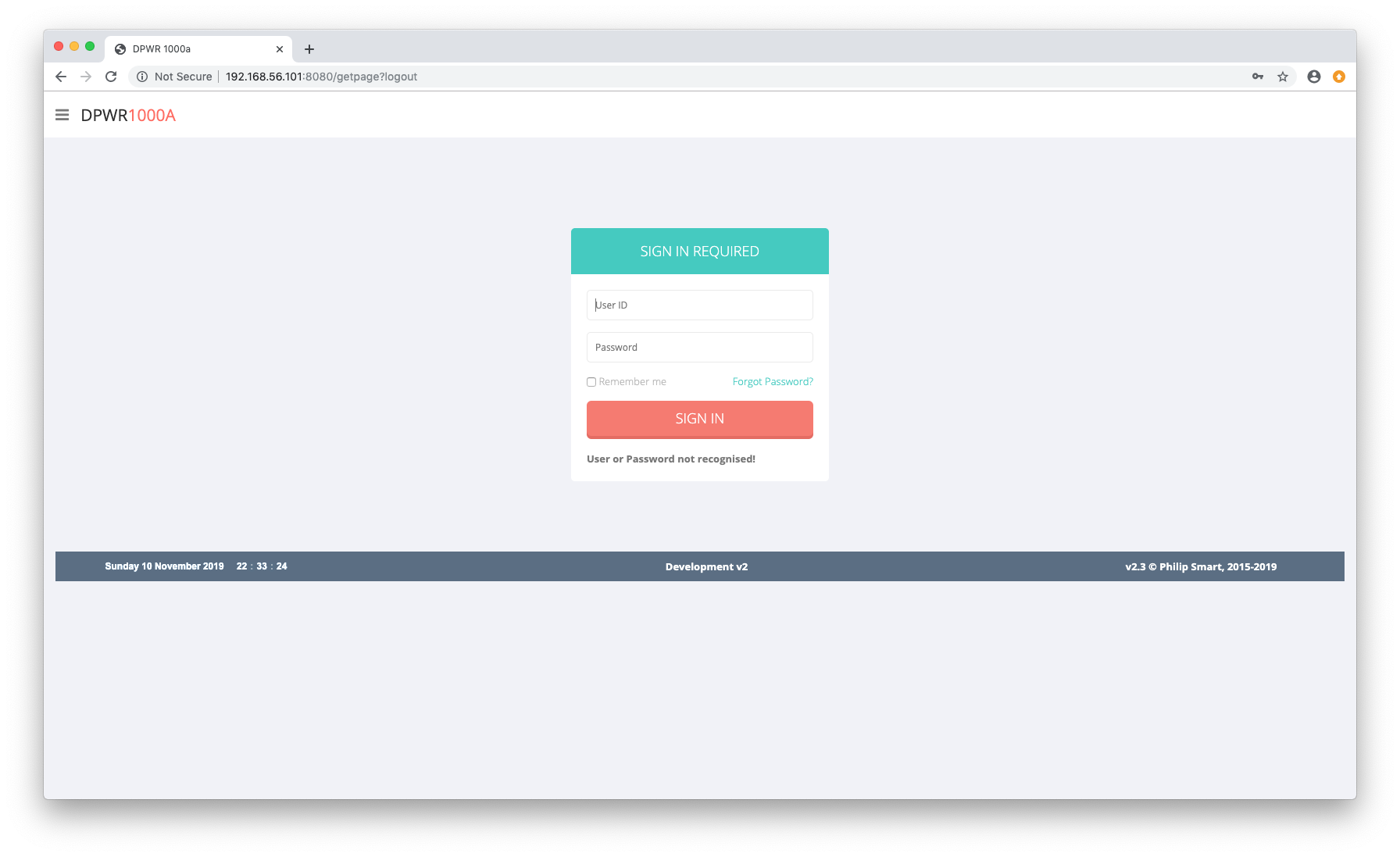
Login is via user/password. 4 users are pre-defined, each with varying privileges.
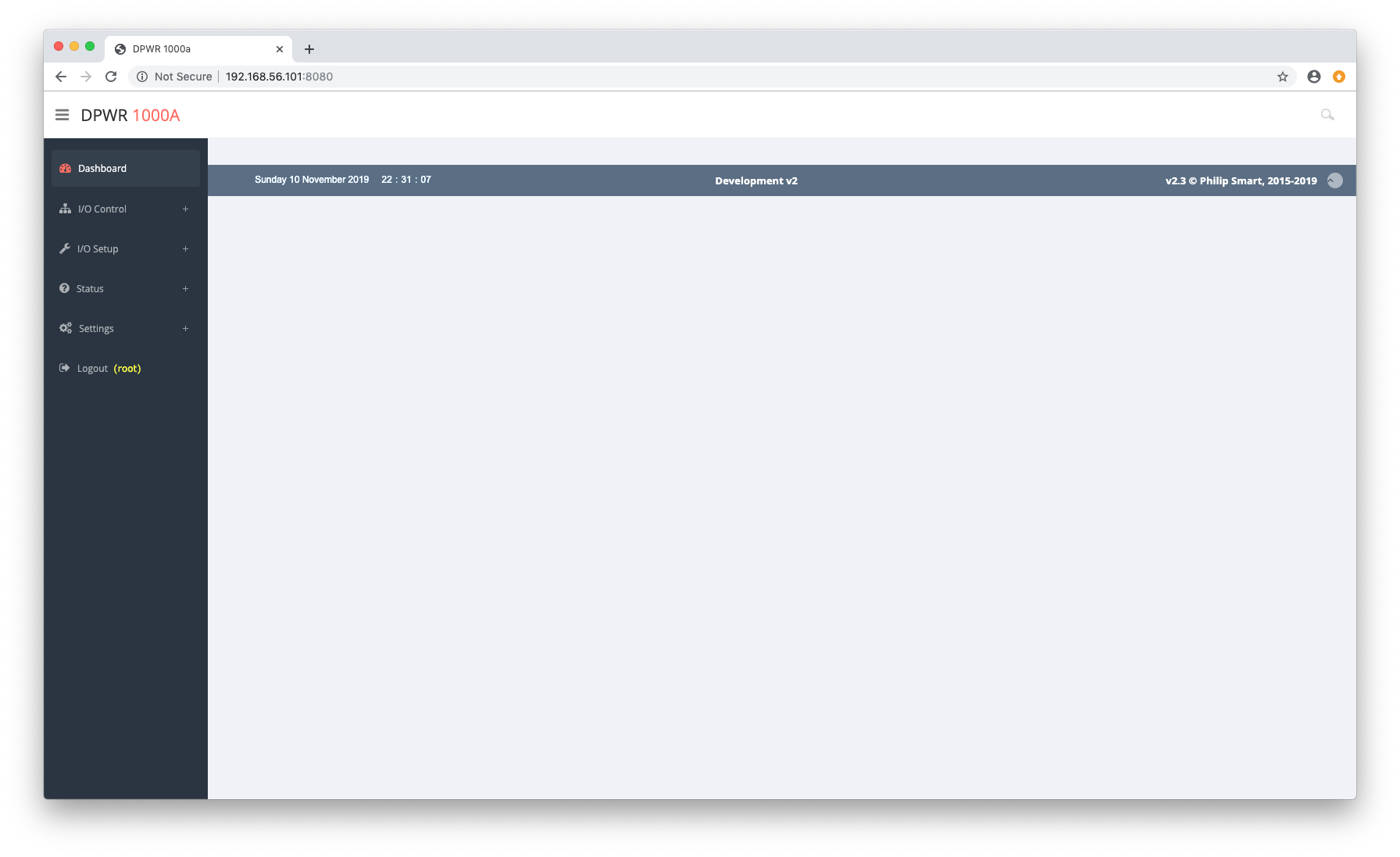
The home screen - blank - but easy enough to add status or other required data/instructions.
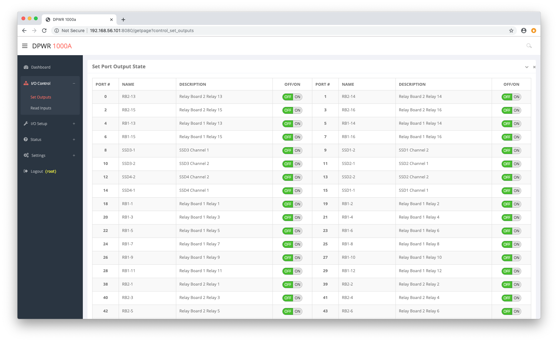
The primary output control screen. Each port which is enabled and configured for output is display along with a description and an on/off switch. Simple enough to change a controlled device state. If more than one user is using the system, ticking Auto Refresh will update this view should another user change a switch.
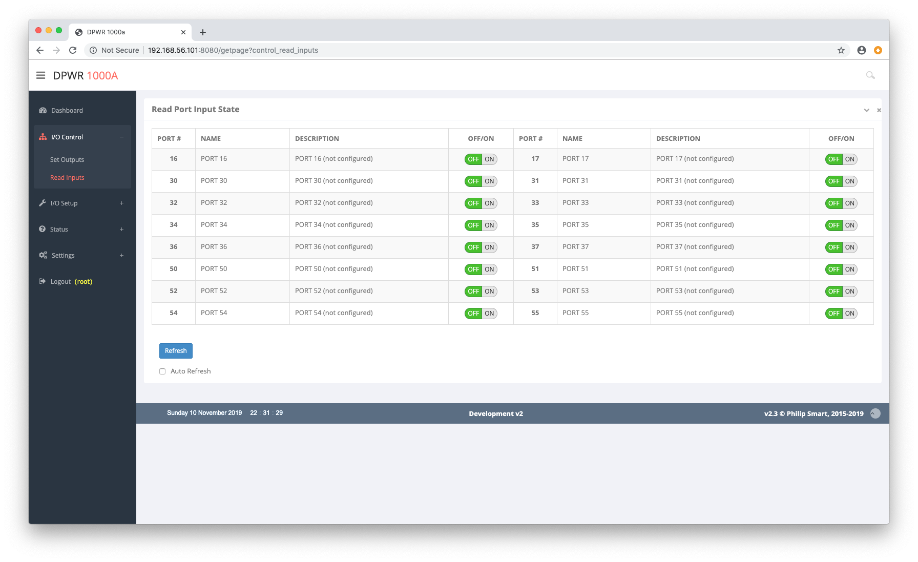
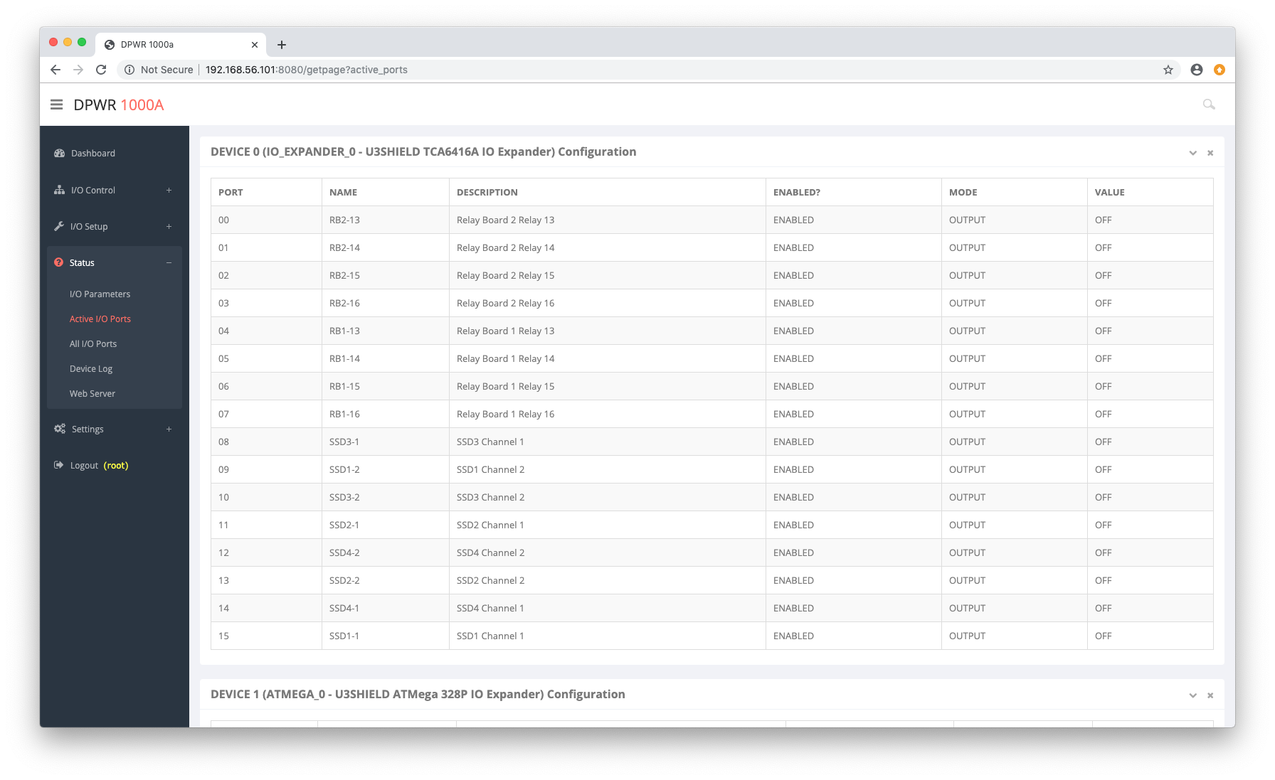
The primary input status screen. Each port which is enabled and configured for input is displayed along with its current value in the form of an on/off switch. Ticking Auto Refresh will periodically (configurable) re-read the device and display the status.
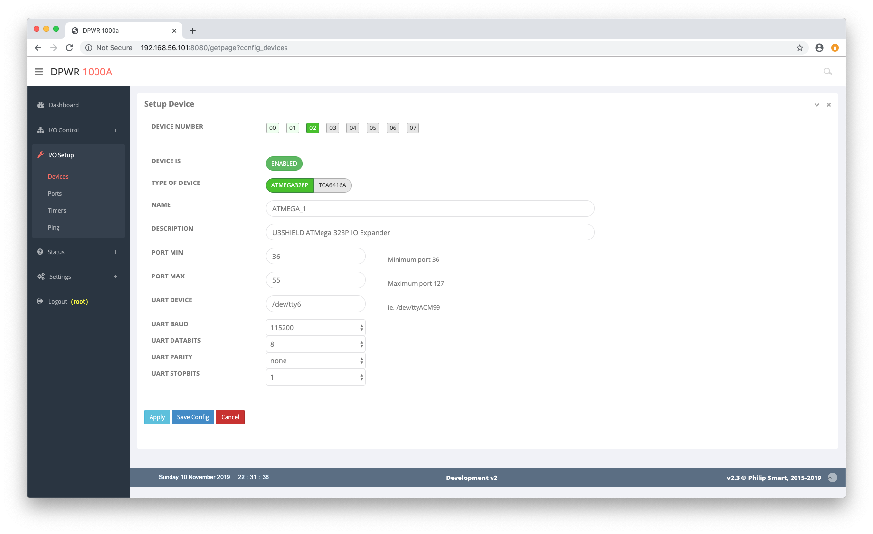
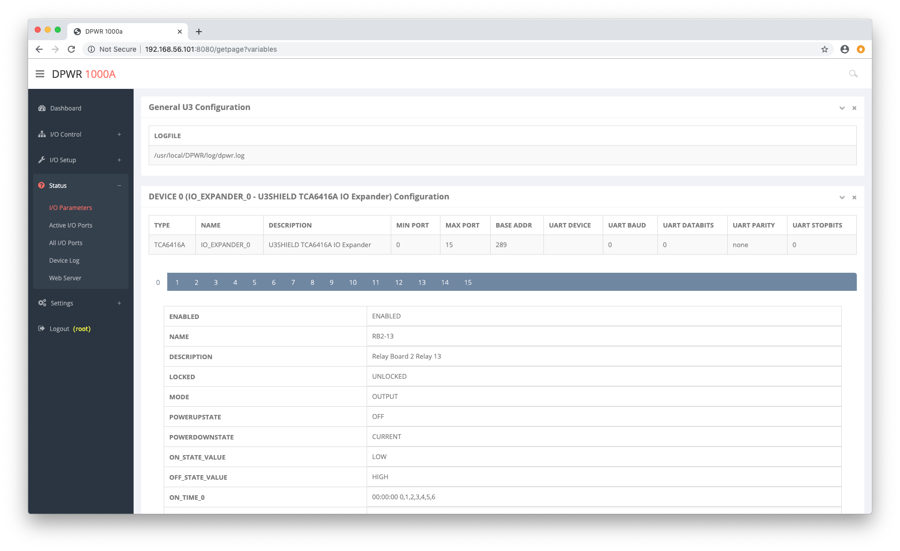
Setup Devices screen. Here you can add a device and set its configuration data. Enabled devices have there ports assigned to the global pool.
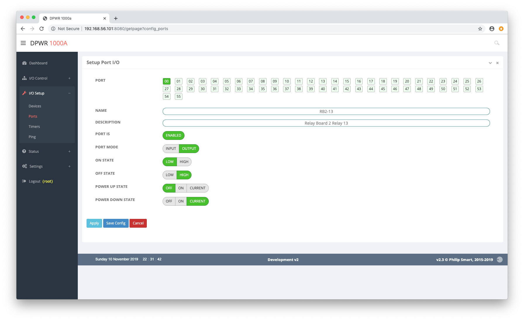
Setup Port screen. Here you can enable/disable a port and configure its settings.
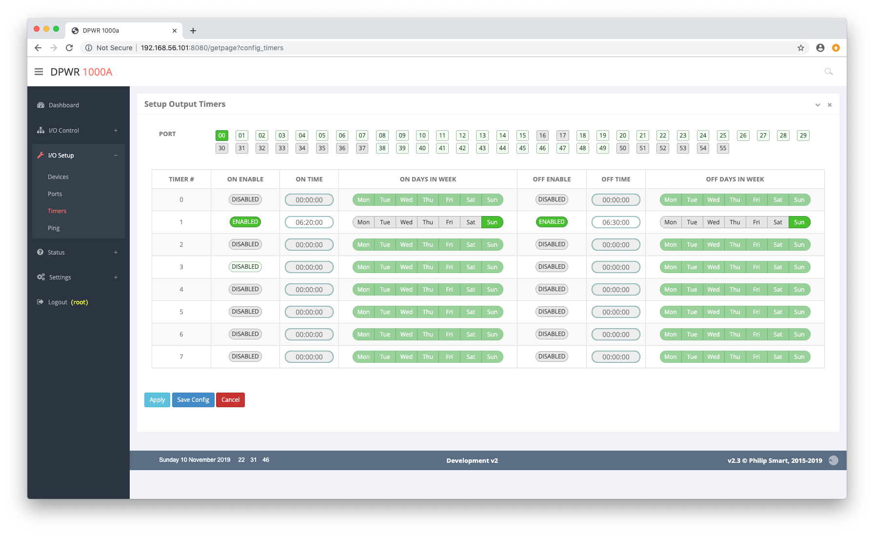
Port Timers screen. Here you can setup output ports to run on a schedule, there are 8 timers per port.
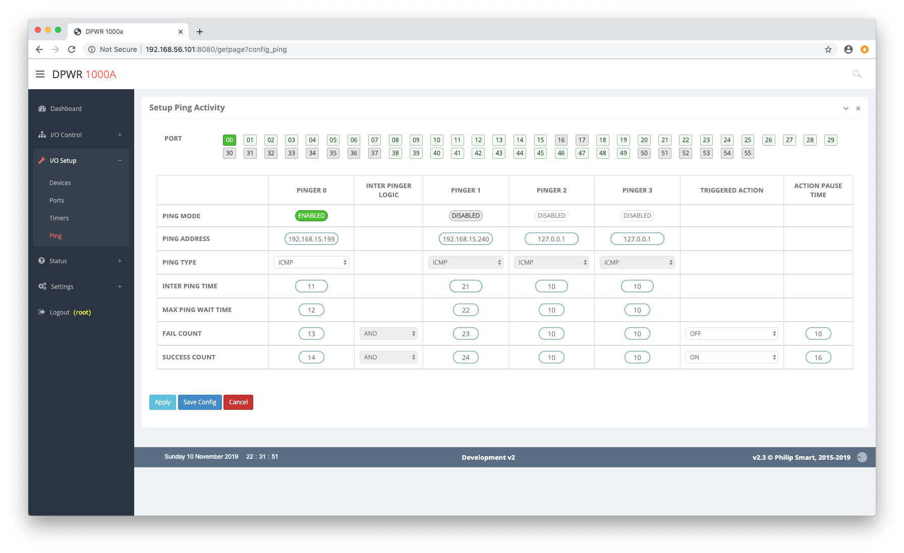
Port change on Ping Activity screen. Here you can configure a port to be changed according to a successful network ping. ie. If a port is controlling a router and a ping cannot be established after the set times, it will automatically power down the router and bring it back up.
The following screens allow a user to see the status of the dPWR hardware.
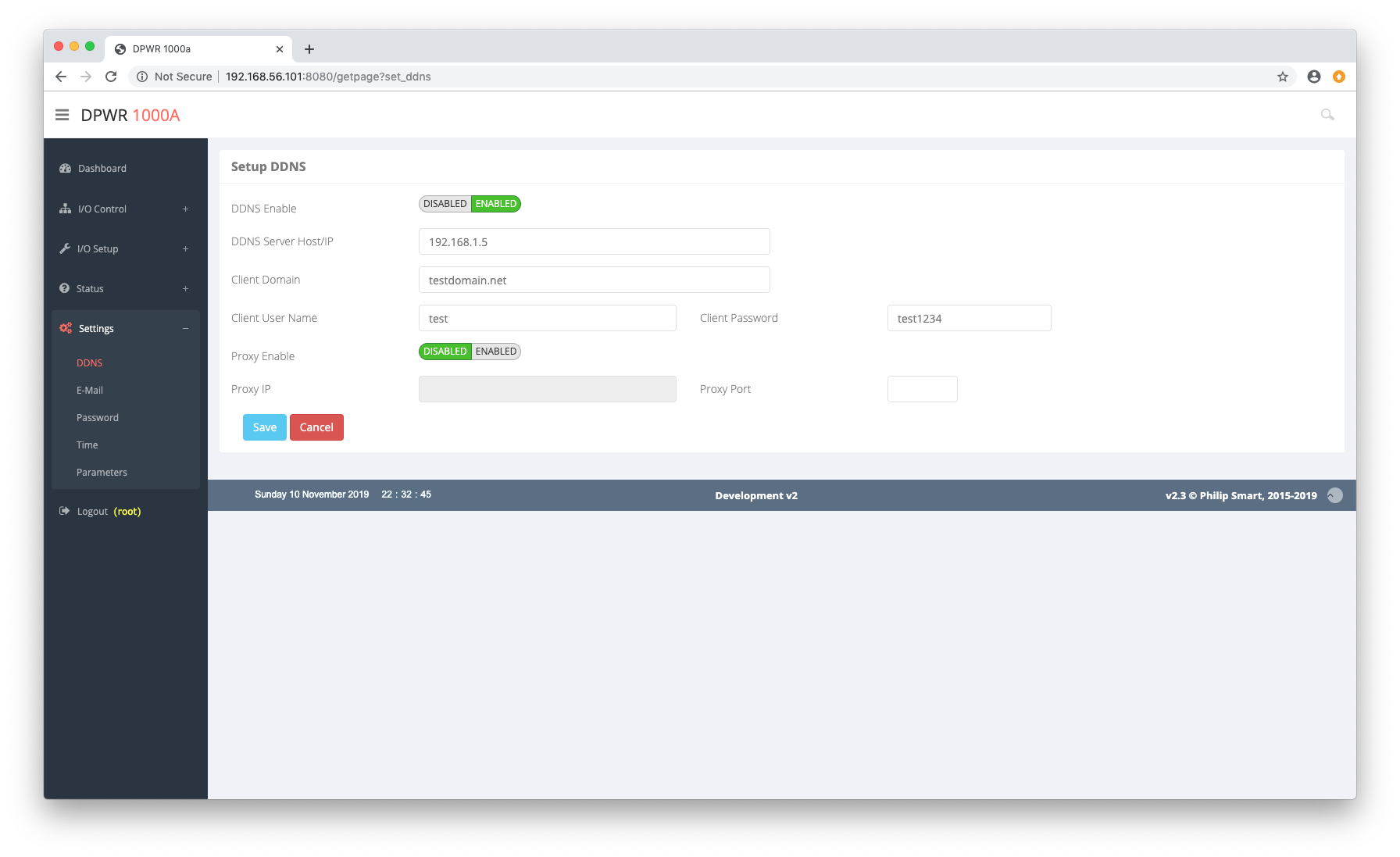
DDNS Setup screen. This allows you to configure an automated Dynamic DNS update. If the dPWR is behind a dynamic IP address which changes, using this option can update a Dynamic DNS hostname with the current IP so that you can always contact the dPWR.
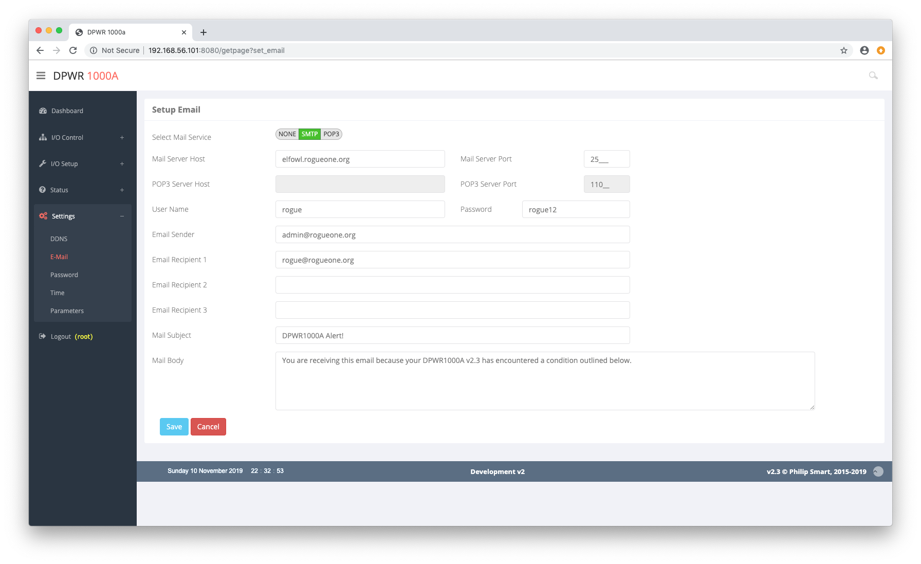
Email setup screen. This allows you to configure an email alert when a state change occurs, ie. a pinger fails and auto restarts a device.
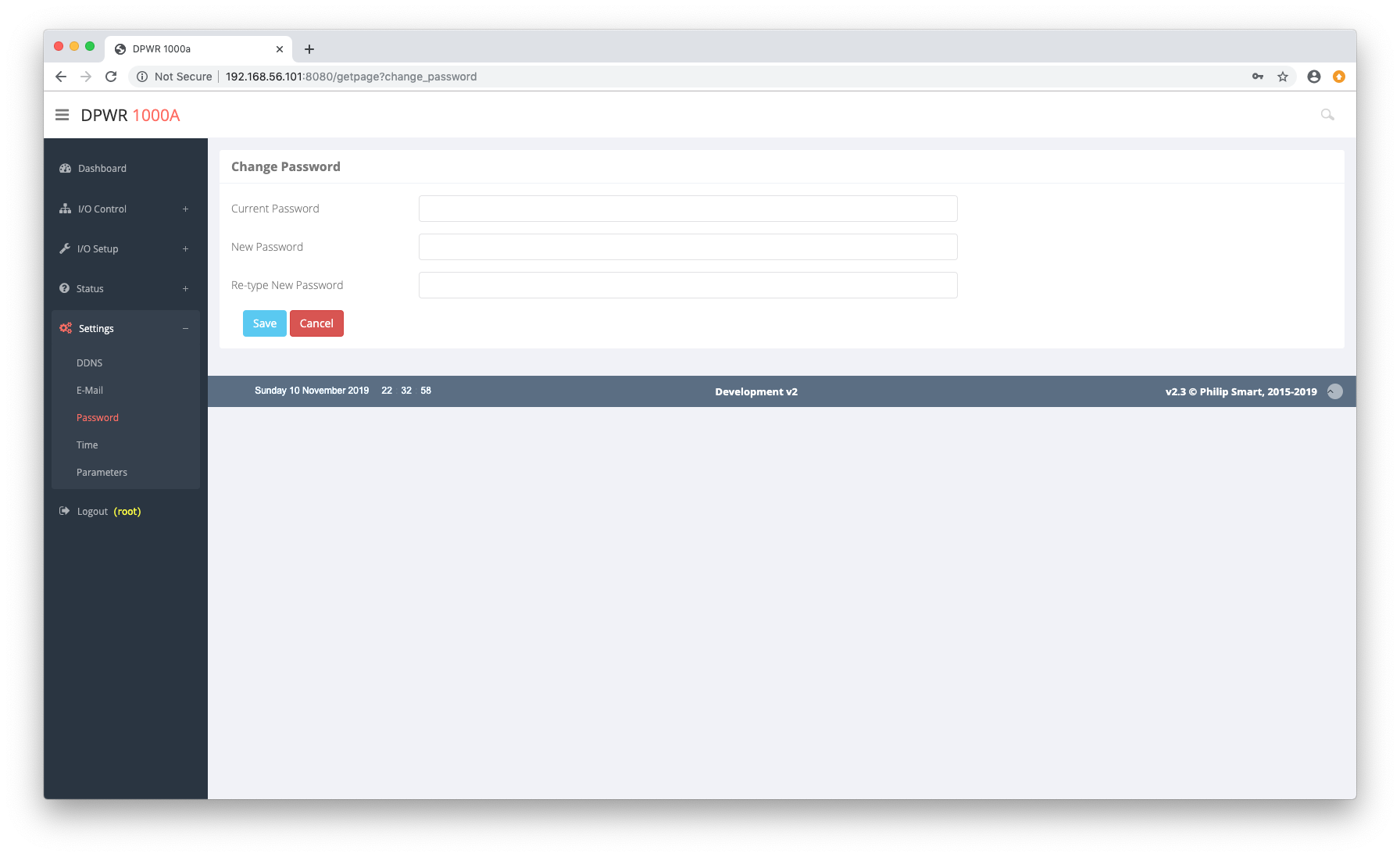
Change the current user password screen.
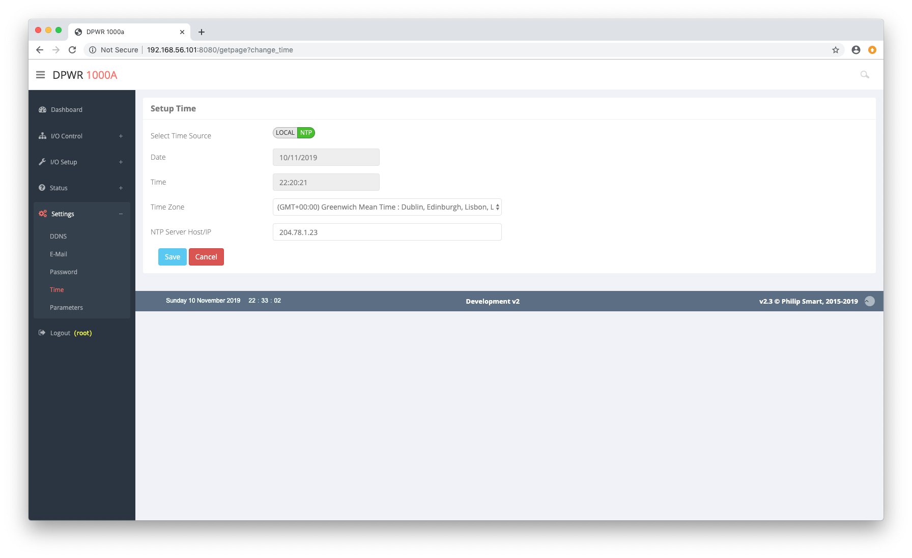
Time setup screen. This allows you to enter the current date and time (required if using timers) either manually or via an NTP service.
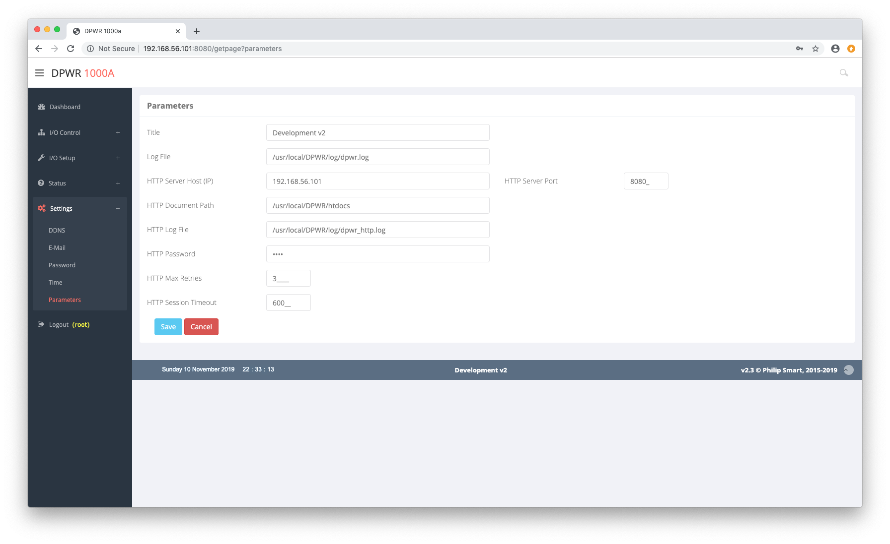
dPWR configuration parameters setup screen. Change specific dPWR runtime values.
To Do
- Finish this document into a more usable installation guide.
Images of the dPWR Hardware Components

The original dPWR after final assembly. All the boards are layed out in 2 spare cases I had.
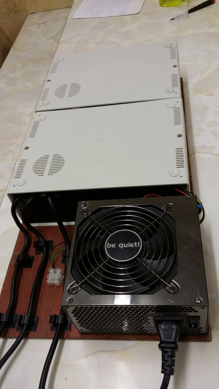
The finished product. One Corsair PSU powered the unit and a number of 12V devices but a 2nd was added later for additional power to control additional devices.
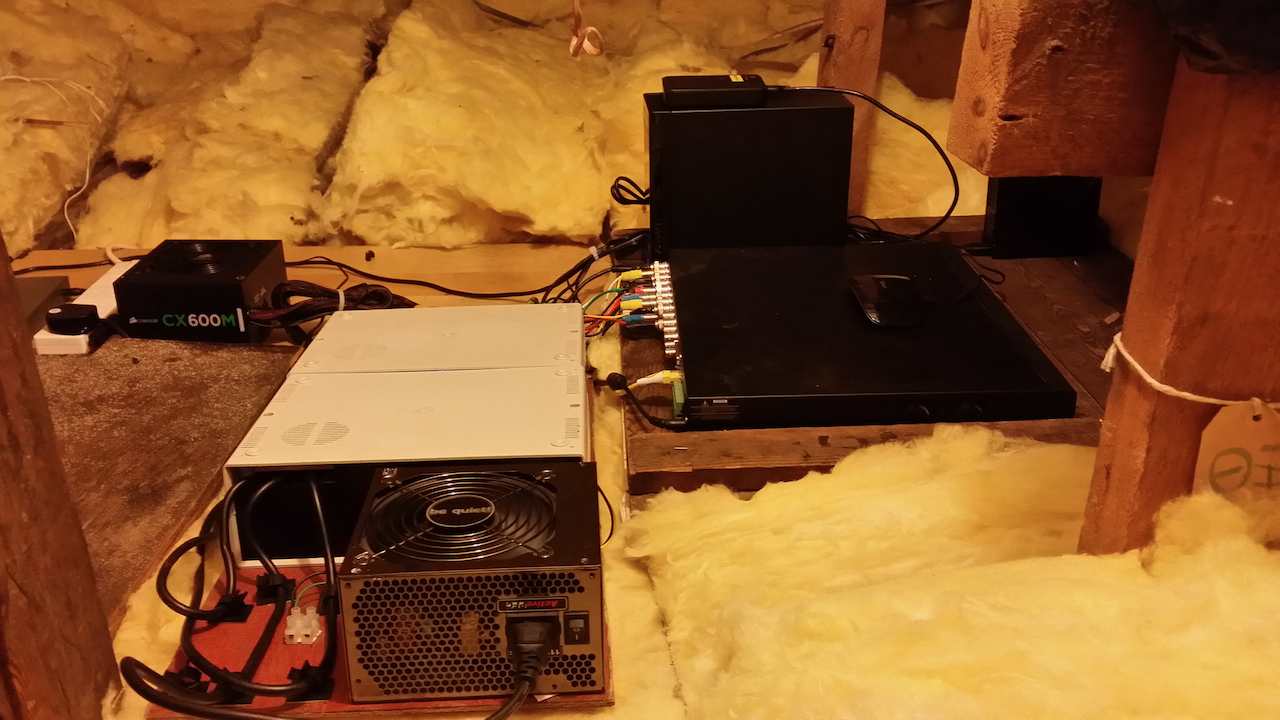
The hostile environment the hardware was located, ran flawlessly for 4 years before one of the Corsair PSU units failed.
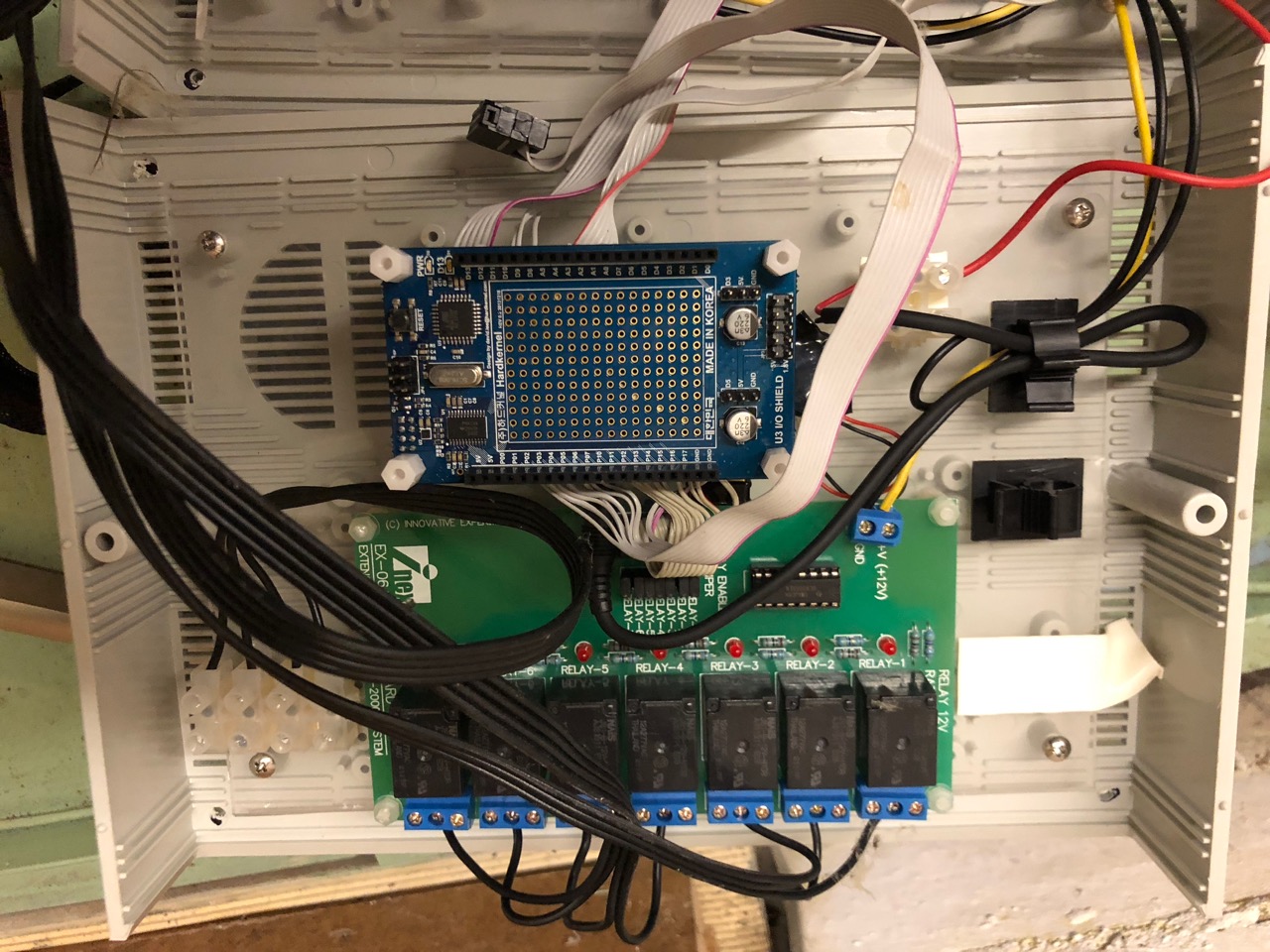
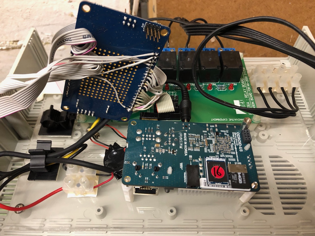
The Odroid U3 (running dPWR), shield and TCA6416A IC along with an 8 channel EX-06A Relay board used to switch low DC voltages.
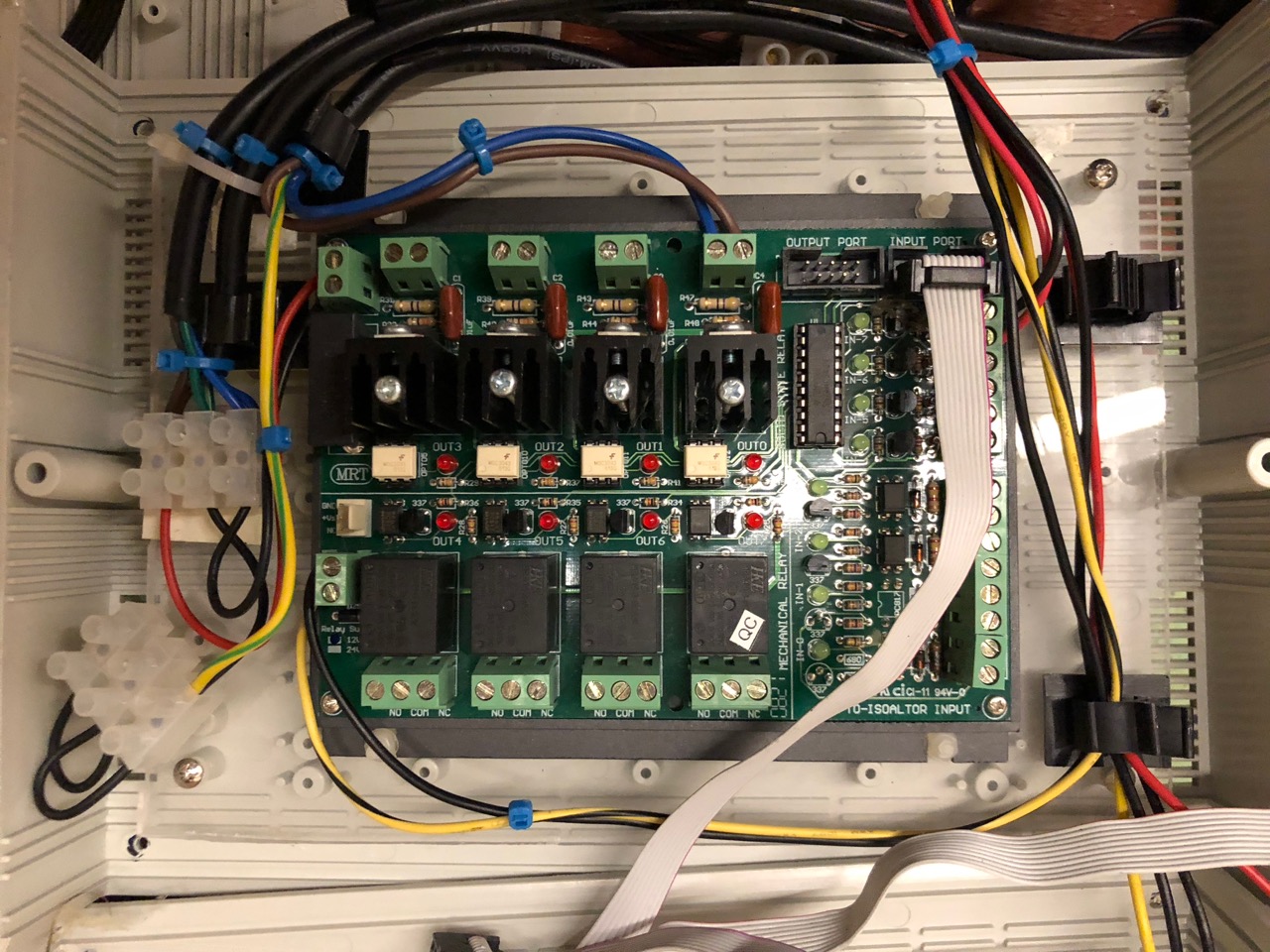
An opto-isolated mains switching (230vac) board using Thyristors and Relays with readback.
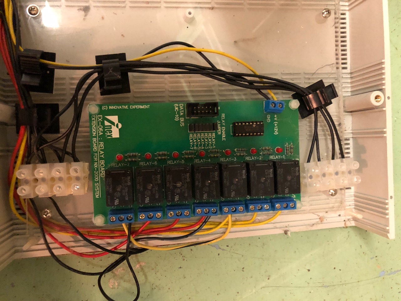
A second EX-06A for low switching DC voltages.

One of 2 Corsair 750W PSU’s. The dPWR unit was housed in a loft which was not such an hospitable environment (cold in winter, very hot in summer) but they managed to last 4 years!
The U3 Shield seperated from the Odroid-U3 dev board. HardKernel make some lovely development boards from low power to multi-processor using Samsung chipsets.
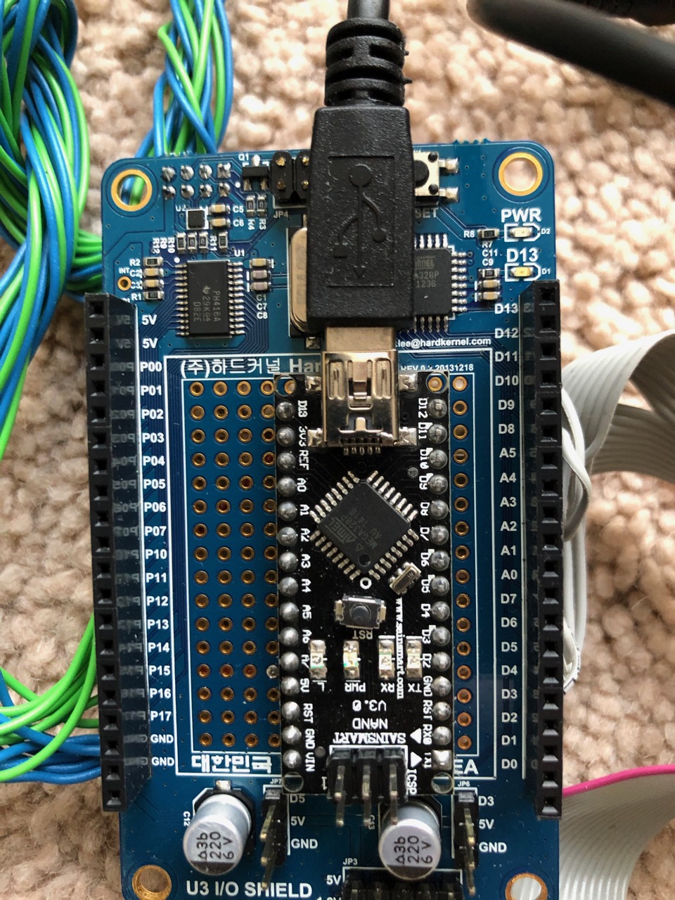
The Nano ATMega328p from SainSmart. This module was used as an intelligent I/O expansion within dPWR albeit the ‘intelligent’ part was never really used. It was in my parts bin and proved reliable.
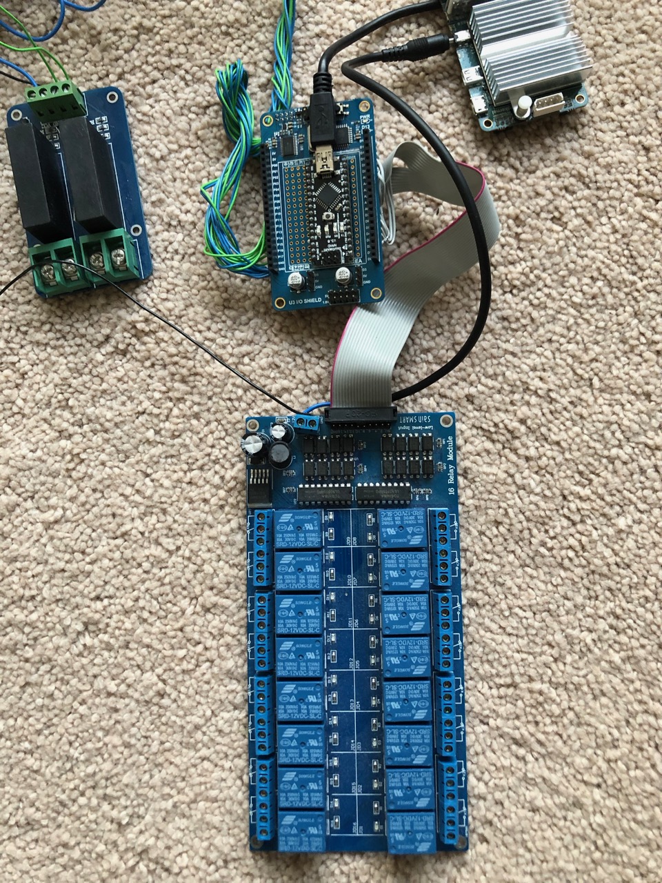
A Sainsmart 16 Channel Relay board hooked up to the ATMega328p I/O expander. This board proved reliable for low and high voltage switching.
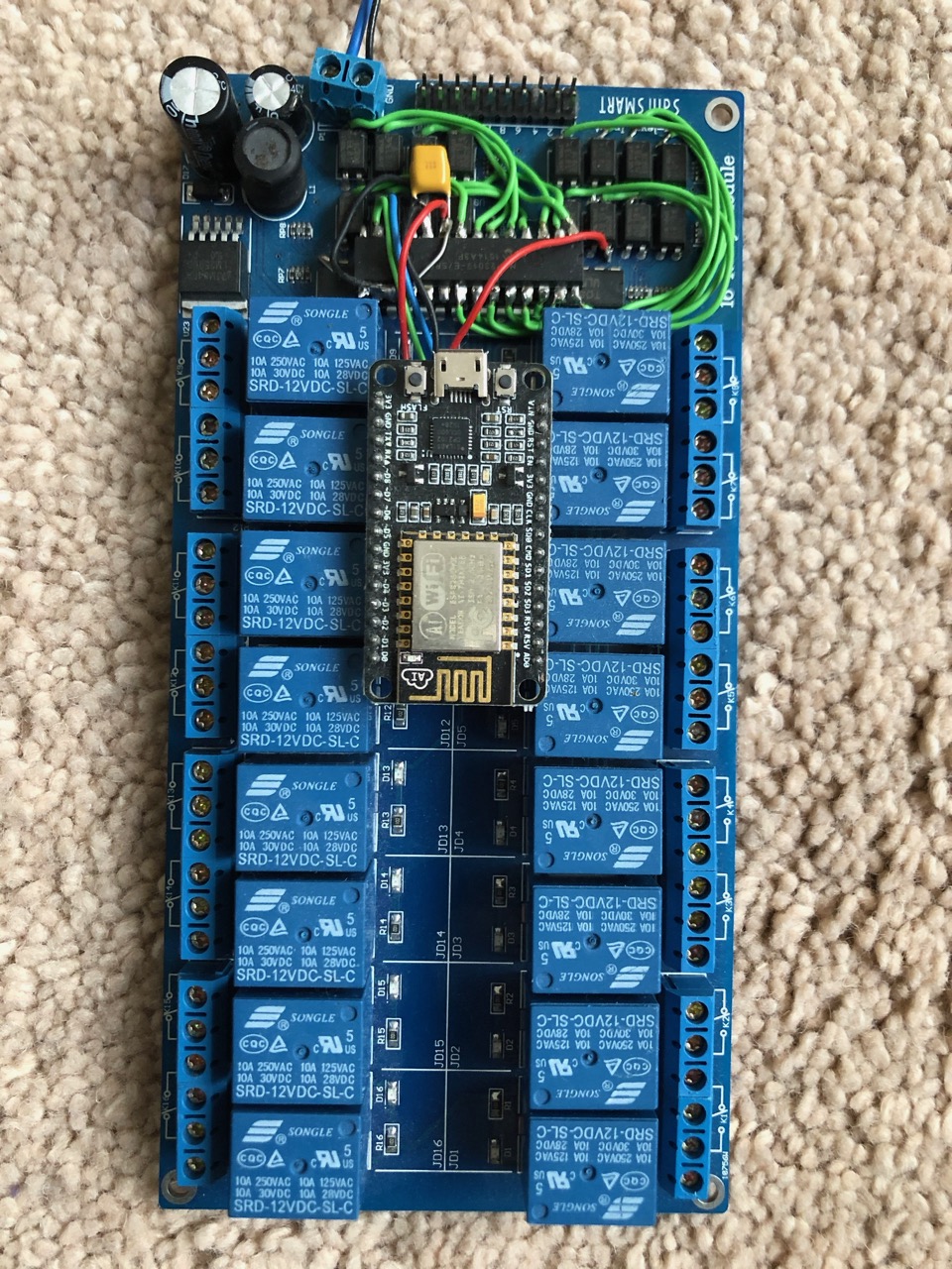
A Sainsmart 16 channel relay board modified with an ESP8266 controller. This board never made it into production as it depended on a wifi connection being established with an access point in order to connect with the main dPWR U3 board. It basically worked but the wifi wasnt reliable enough.
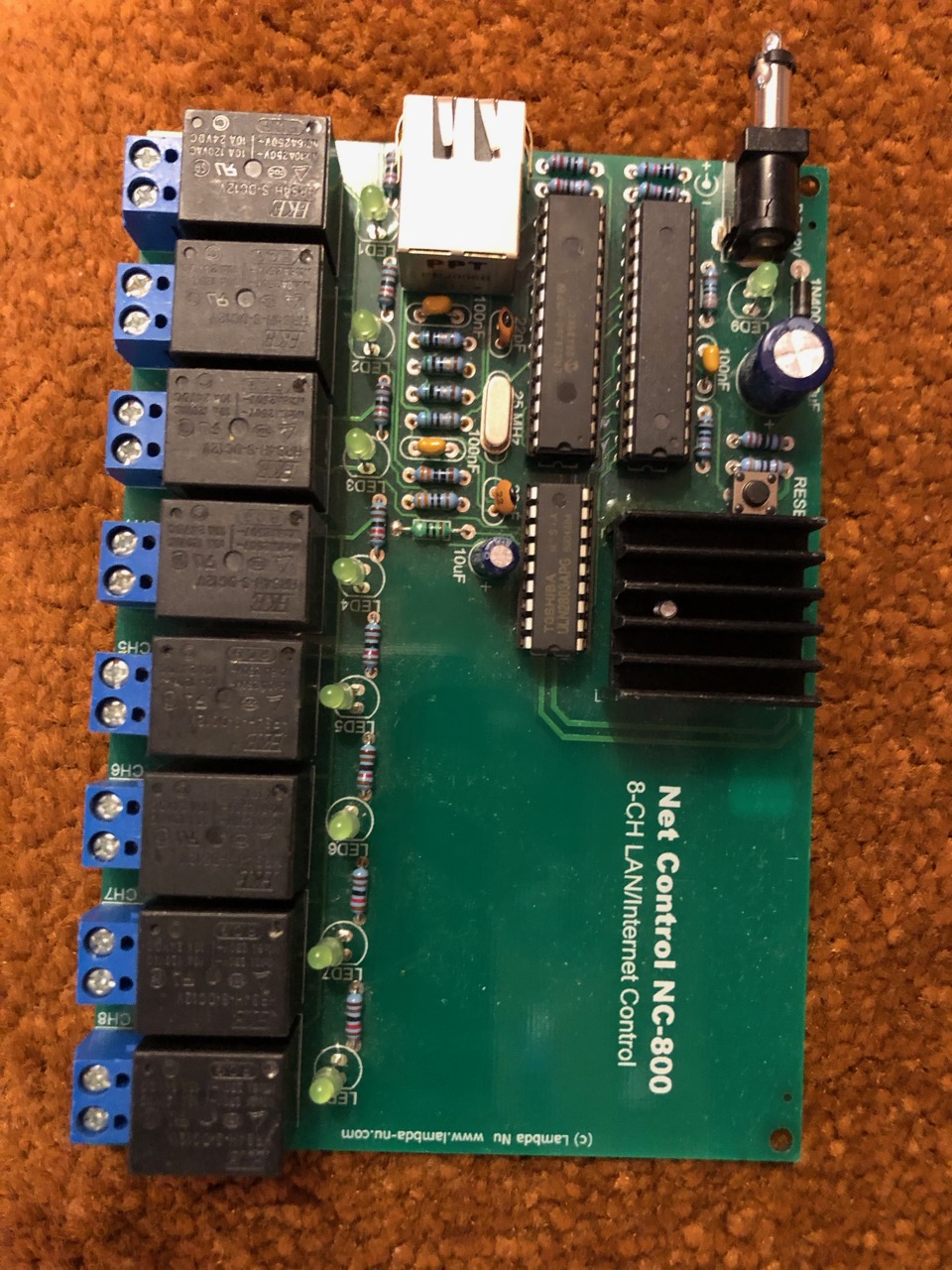
The NC800 Ethernet based board, I worked on the module to control it but never actually used it in production. This kind of board would be ideal for remote control if an ethernet link and PoE was available.
Credits
Where I have used or based any component on a 3rd parties design I have included the original authors copyright notice within the headers or given due credit. All 3rd party software, to my knowledge and research, is open source and freely useable, if there is found to be any component with licensing restrictions, it will be removed from this repository and a suitable link/config provided.
Licenses
This design, hardware and software, is licensed under the GNU Public Licence v3.
The Gnu Public License v3
The source and binary files in this project marked as GPL v3 are free software: you can redistribute it and-or modify it under the terms of the GNU General Public License as published by the Free Software Foundation, either version 3 of the License, or (at your option) any later version.
The source files are distributed in the hope that it will be useful, but WITHOUT ANY WARRANTY; without even the implied warranty of MERCHANTABILITY or FITNESS FOR A PARTICULAR PURPOSE. See the GNU General Public License for more details.
You should have received a copy of the GNU General Public License along with this program. If not, see http://www.gnu.org/licenses/.