 picoZ80
Overview
The picoZ80 continues the tranZPUter theme, replacing a physical Z80 in a host or industrial computer with a
faster CPU, more memory, virtual devices, networking (WiFi, BT), rapid application loading from SD card and WiFi management.
It is a custom PCB designed to drop directly into the Z80 DIP-40 CPU socket of any legacy Z80-based computer. Rather than using a discrete Z80 processor, the board hosts an RP2350B microcontroller — a dual-core 150MHz Cortex-M33 device capable of running at up to 300MHz — whose programmable I/O (PIO) state machines take full, cycle-accurate control of the Z80 address, data, and control buses.
The picoZ80 is not a simple emulator adapter. Every bus transaction is handled in real time by the RP2350's PIO engines, giving the host system exactly the same bus timing it would see from a real Z80. At the same time, the RP2350's second core and abundant on-chip SRAM, combined with 8MB of external PSRAM and 16MB of Flash, allow an almost unlimited range of capabilities to be layered on top of the raw Z80 interface — including accelerated execution, virtualised memory, ROM banking, virtual disk drives, and full machine-persona emulation.
An ESP32 co-processor provides WiFi and Bluetooth connectivity, SD-card mass storage, and a browser-based management interface. All configuration is driven from a single human-readable
config.json file stored on the SD card, meaning no recompilation is required to reconfigure the board's memory map, ROM images, or driver selection.
The picoZ80 has been demonstrated running within multiple Sharp MZ machines. A set of personas are being developed for these
machines, indeed for other Z80 systems in time, to provide much needed features, such as banked RAM/ROM, floppy disk emulation,
QuickDisk emulation, ROM Filing System, TranZPUter Filing System, all capable of being functional simultaneously.
The configuration is entirely JSON-driven, adding support for a new Z80-based host is a matter of editing a configuration file and, where new I/O behaviour is required, adding a small C driver
into the codebase.
- Drop-in Z80 replacement
- installs in any Z80 DIP-40 socket. The host sees normal Z80 bus timing throughout. - Cycle-accurate PIO bus interface
- three RP2350 PIO state machines handle address, data, and control signals simultaneously at full Z80 bus speed. - Large memory space
- 8MB PSRAM organised as 64 banks × 64KB, giving a total of 4MB of banked address space accessible per CPU context. - ROM/RAM banking
- memory blocks are configurable in 512-byte granularity and can be mapped as ROM, RAM, physical host memory, or virtual function handlers. - Virtual device framework
- any 512-byte block of memory or I/O port range can be backed by a C function, enabling fully virtualised peripherals. - Machine personas
- the Z80 firmware can be configured via a jSON config to work within any Z80 host. Personas are being developed to add virtual drivers to the host, using the resources of the RP2350/ESP32. Already the MZ-700 persona has a rich repertoire of drivers and this will be extended to the MZ-80A, MZ-80B, MZ-800 and other Sharp machines. The intent is to also extend the persona repertoire to other machines such as the Amstrad PCW. - Floppy and QuickDisk emulation
- WD1773-compatible floppy disk controller and Sharp QuickDisk drive emulation, using DSK/RAW images on the SD card. - WiFi and web management
- the onboard ESP32 provides a seven-page Bootstrap web interface for configuration, file management, OTA firmware updates, and persona selection. - Dual firmware partitions
- two independent 5MB firmware slots allow safe OTA upgrades; the active partition is selected from the web interface or bootloader. - USB firmware update
- the bootloader exposes a USB bridge for firmware flashing without requiring a hardware debugger.
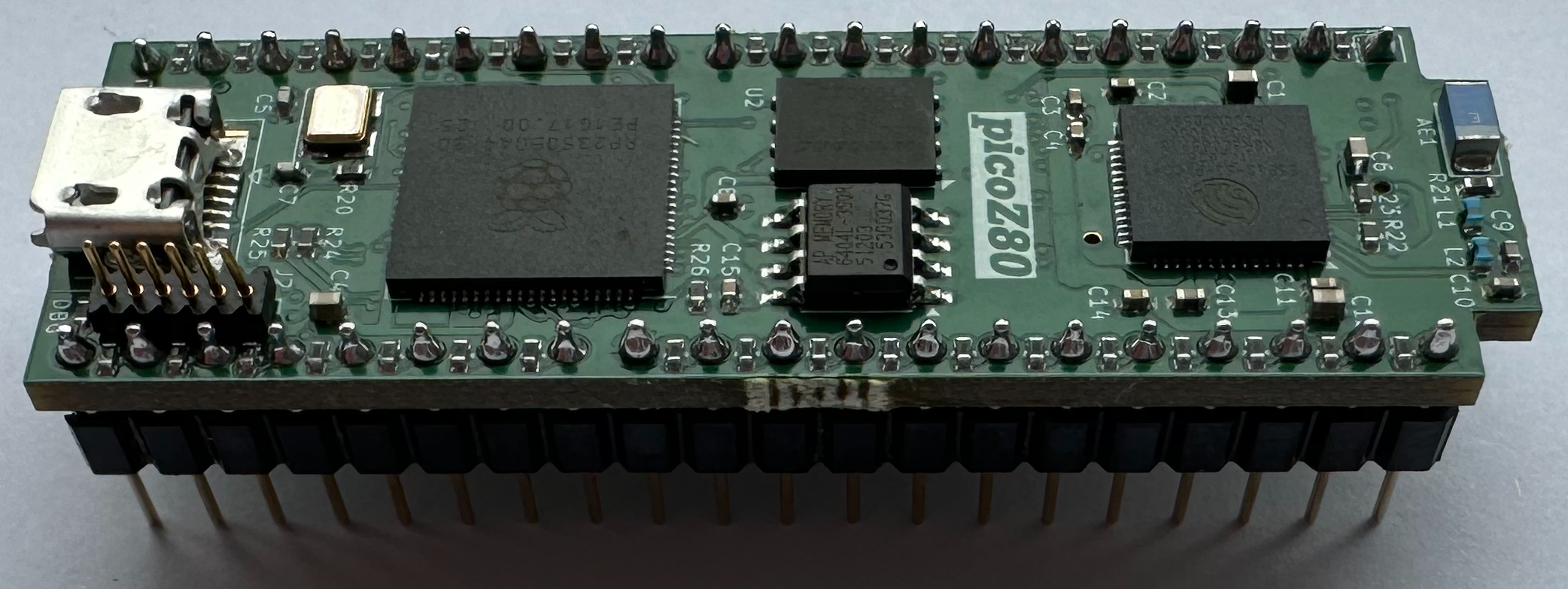
Hardware
The picoZ80 PCB (revision 2.5) is a compact, multi-layer board designed to fit within the physical footprint of the Z80 DIP-40 package and the clearance available inside typical retro-computer cases. All logic operates at 3.3V; level shifting and drive current considerations for the 5V host bus are handled in the schematic design.
The board integrates five subsystems on a single PCB: the RP2350B processor, the Z80 bus interface, the ESP32 co-processor, the power supply, and a USB hub.
Key Components
- RP2350B (Cortex-M33 dual-core)
- primary processor, running at up to 300MHz. Executes the Z80 emulation hot loop on Core 1 and handles file I/O, USB, and ESP32 relay on Core 0. 512KB on-chip SRAM. The RP2350B variant (as opposed to RP2350A) provides 48 GPIO pins required for the full Z80 bus. - 16MB SPI Flash
- stores the bootloader, two application firmware slots, two configuration slots, and a general configuration partition. Total addressable layout spans 0x10000000–0x11000000. - 8MB PSRAM (SPI)
- external pseudo-static RAM providing 64 banks × 64KB of banked address space for the emulated CPU. Connected to the RP2350 via a dedicated SPI peripheral. - ESP32 co-processor
- provides WiFi (802.11 b/g/n, AP and client modes), Bluetooth, SD-card reader, and web server. Communicates with the RP2350 via 50MHz FSPI and a 460.8kbaud UART. - SD card slot
- FAT32, managed by the ESP32. Storesconfig.json, ROM images, disk images (DSK, QuickDisk, RAM disk), and TZFS/RFS filing system trees. - USB hub
- on-board USB hub for host connectivity and firmware update bridging. - 3.3V power supply
- efficient buck converter drawing from the 5V present on the Z80 socket VCC pin.
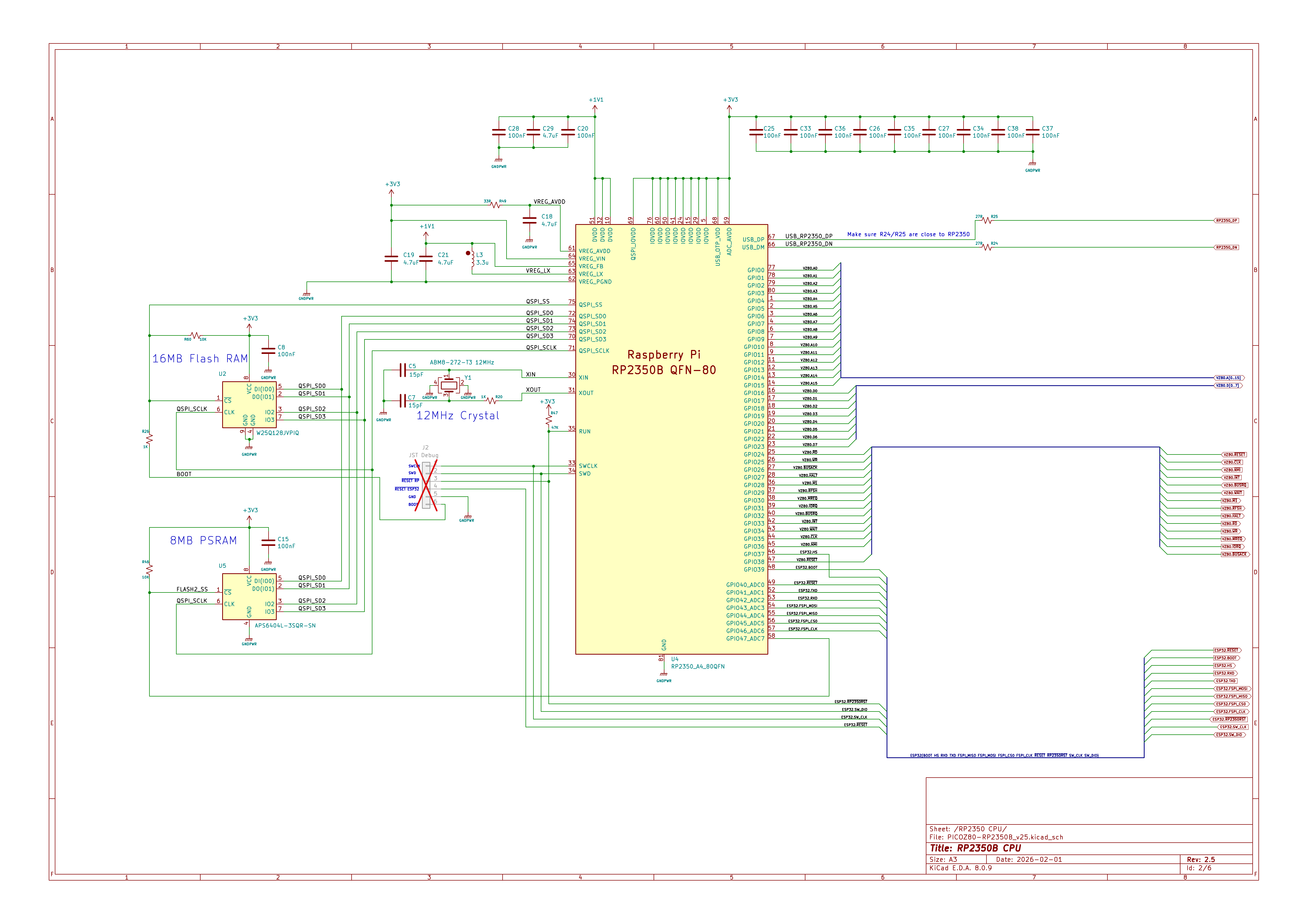
The picoZ80 hardware is designed in KiCad. The current revision is v2.5. Schematic and PCB layout files are available in the project repository under
Sheet 1 — RP2350B Processor
kicad/PICOZ80/.
The schematic is divided into five sheets:
All RP2350B GPIO assignments, decoupling, 12MHz crystal oscillator, 16MB Flash, and 8MB PSRAM connections. The RP2350B QFN-80 package is chosen specifically for its 48-GPIO count — the full Z80 bus (16 address + 8 data + 12 control signals) plus ESP32 SPI/UART and USB signals consume virtually every available pin.
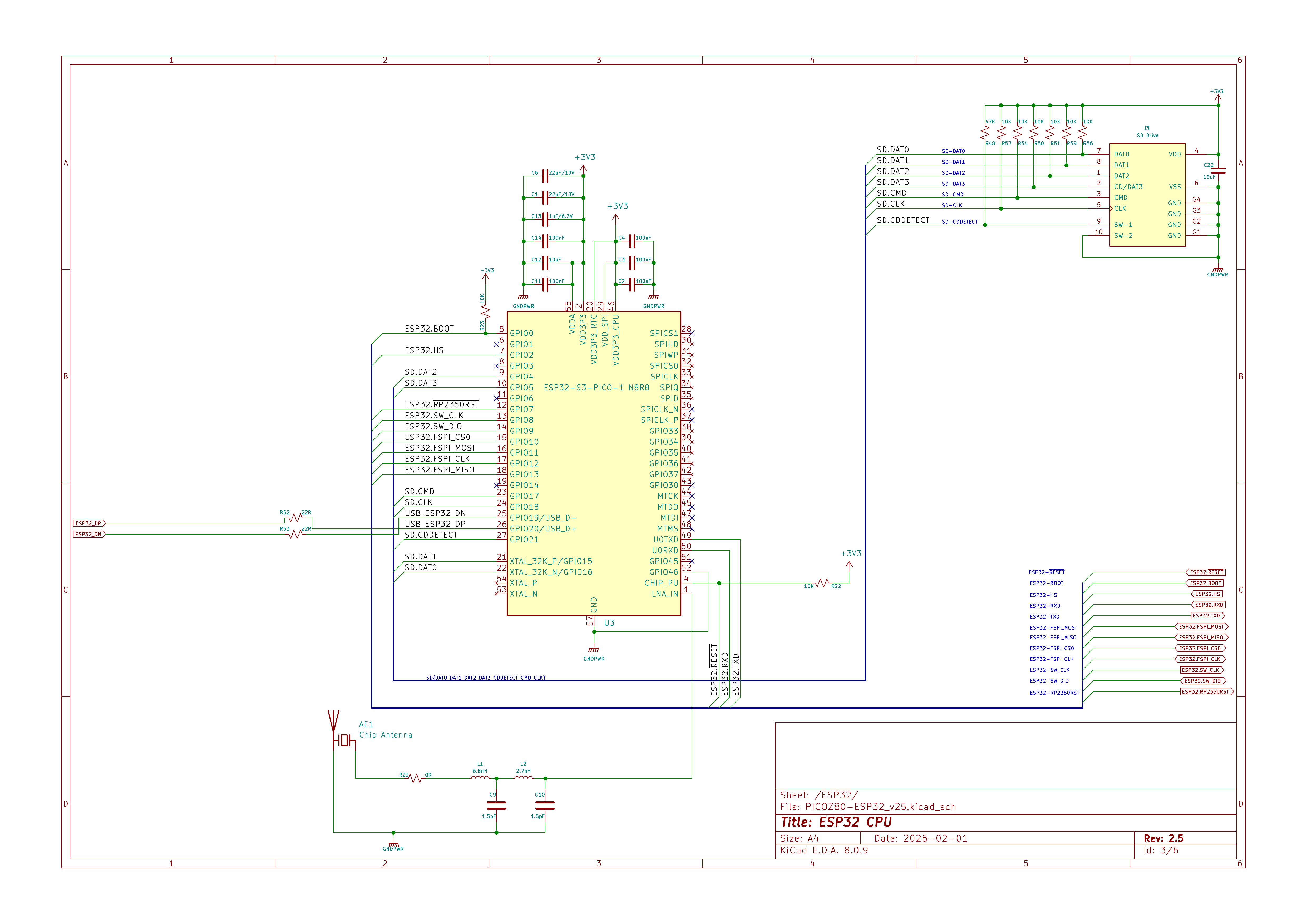
ESP32-S3-PICO-1 module, SD card interface (SPI), chip antenna, debug header, and inter-processor communication lines (FSPI bus at 50MHz, UART at 460.8kbaud). The SD card signals and inter-processor SPI/UART are clearly separated in this sheet.
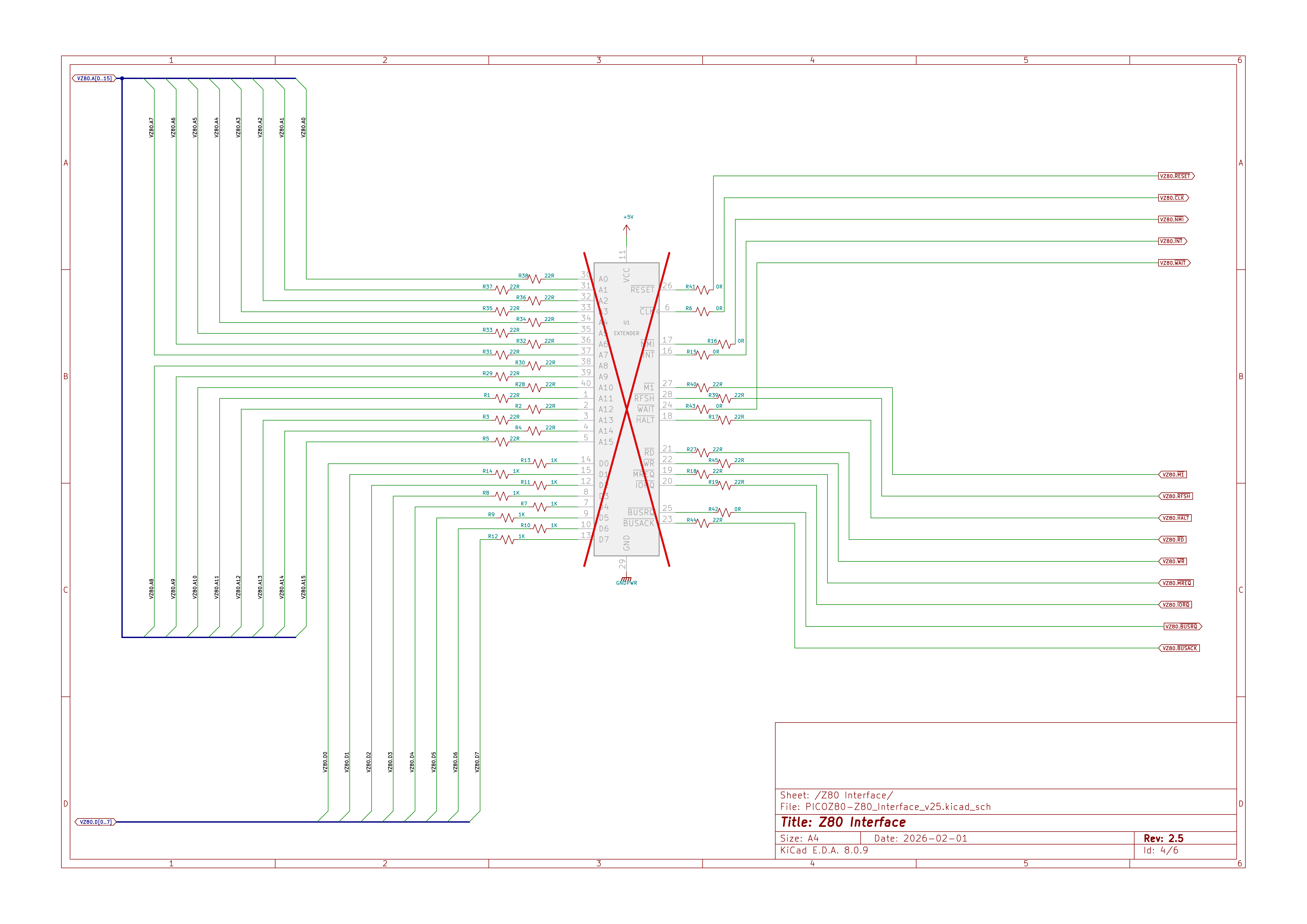
The 40-pin DIP socket connections and bus interface resistor network. Address lines A0–A15, data lines D0–D7, and all Z80 control signals (MREQ, IORQ, RD, WR, M1, RFSH, BUSREQ, BUSACK, HALT, INT, NMI, WAIT, CLK, RESET) are routed through series resistors to dedicated RP2350 GPIO pins monitored by the PIO state machines.
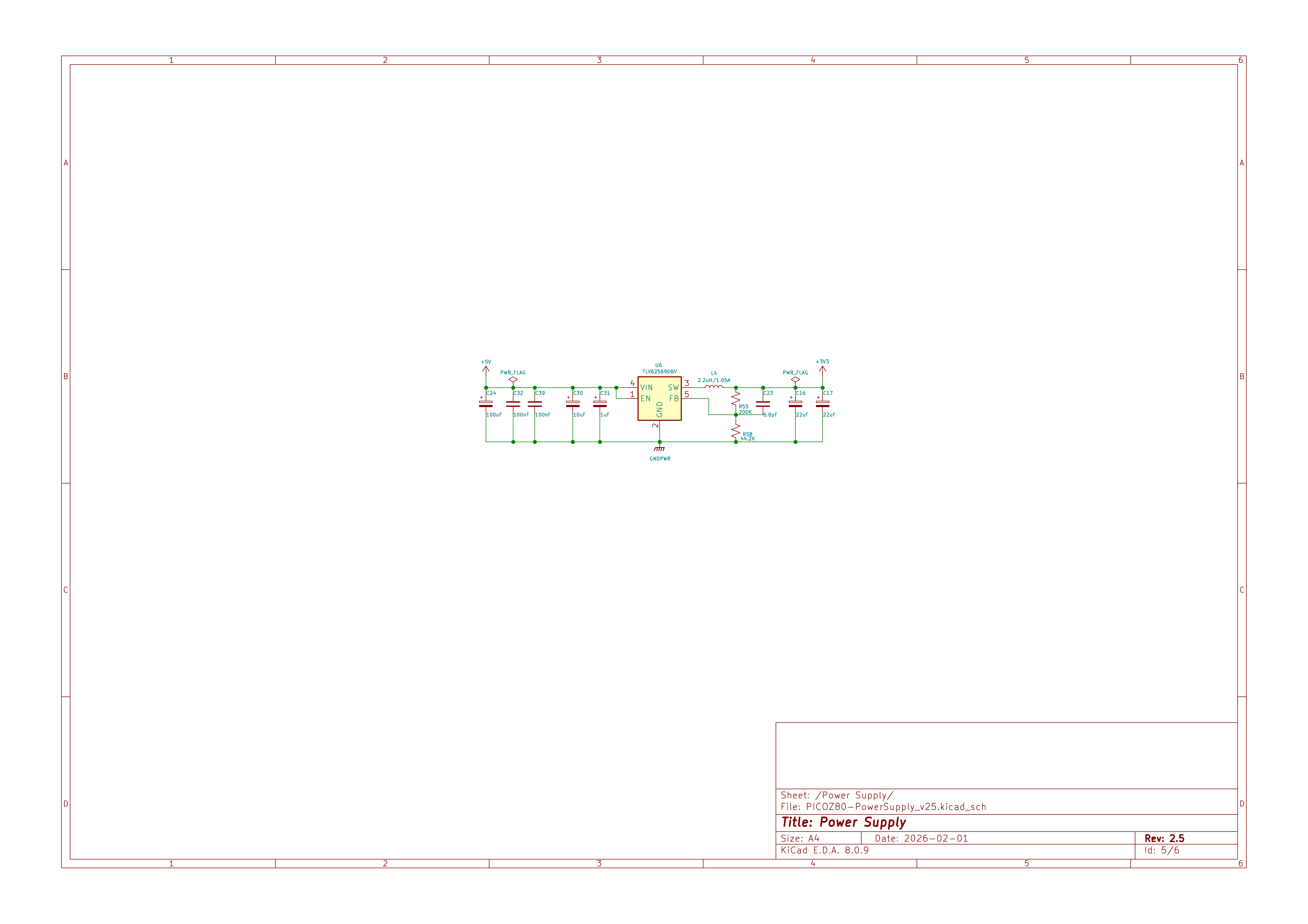
TLV62590BV 5V-to-3.3V synchronous buck converter with input/output filtering capacitors. The converter must supply the combined load of the RP2350B at up to 300MHz, 8MB PSRAM, ESP32, and USB hub from the single 5V VCC pin of the Z80 DIP-40 socket.
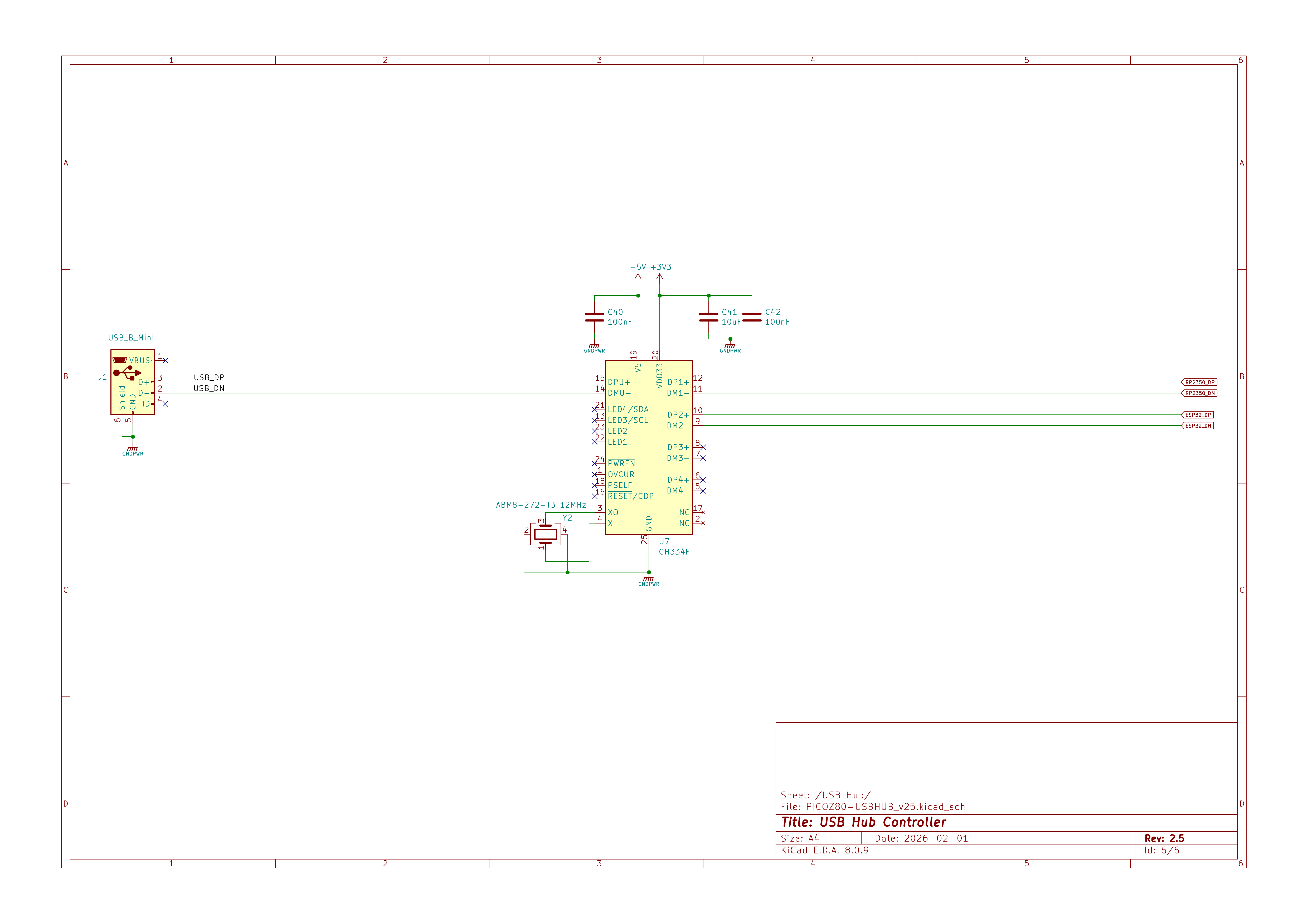
CH334F USB hub controller with Mini-B connector, 12MHz crystal, and downstream ports routed to both the RP2350 (for firmware update bridging) and the ESP32 (for direct USB access on newer board revisions).
The PCB was designed as small as possible to accommodate all the necessary circuity and fit within the limits of a DIP-40 socket.
The smallest components which could be manually assembled were used, ie. 0402/0603 passive devices and 0.5mm IC pitch spacing to reduce overall size and a 6 layer stackup selected to fit all required components.
Initial designs, v2.0 and v2.1 were manually assembled with point application of solder, manual part placement and a hot-air rework station. Version 2.2 was manually assembled with a stencil and reflow oven. v2.3a and v2.5 were assembled at a PCB Fab.
PCB Overview


Click here to view an interactive PCB component placement diagram and Bill of Materials.
Architecture
Dual-Core Design
The RP2350B's two Cortex-M33 cores are given completely separate responsibilities, communicating through an intercore message queue (
PIO Bus Interface
queue_t).
Core 0 handles all non-real-time tasks: USB bridge and CDC serial, firmware update coordination, file I/O (relayed to the ESP32 over UART), ESP32 command dispatch (floppy/QuickDisk image changes, config reloads, version queries), and partition management.
Core 1 runs the CPU emulation hot loop exclusively. It services the PIO FIFOs to process Z80 bus transactions, resolves each address against the memory map, and either passes the transaction to physical host hardware (PHYSICAL type), services it from PSRAM (RAM/ROM types), or calls a virtual device handler function (FUNC type). Latency on this path is minimised by keeping the inner loop in SRAM and using the 512KB RP2350 SRAM as a fast look-up table for memory-block pointers.
The Z80 bus interface is implemented entirely in RP2350 PIO assembly (
z80.pio). The RP2350 provides three PIO blocks (PIO 0, PIO 1, PIO 2), each with four state machines. The Z80 firmware uses all three PIO blocks:
- PIO 0 — Address and data bus (GPIO 0–23)
- handles the 16-bit address bus (A0–A15, GPIO 0–15) and the bidirectional 8-bit data bus (D0–D7, GPIO 16–23). State machines run thez80_addrandz80_dataprograms simultaneously, pushing address words and driving or sampling data bytes in synchrony. - PIO 1 — Control signals and cycle execution (GPIO 16–47)
- runs the main bus control programs against the upper GPIO range: bus request/acknowledge (z80_busrq), NMI detection (z80_nmi), clock synchronisation (z80_clk_sync), and interrupt-acknowledge handling (z80_int_ack). - PIO 2 — Host timing, reset, refresh, and wait states
- manages the time-critical interactions between the RP2350 and the host Z80 bus that must remain correct even when Core 1 is servicing internal memory. Four dedicated state machines run in PIO 2:- RESET detection (
z80_reset) — monitors the host RESET line and signals Core 1 so that the emulation state can be reinitialised cleanly on every hardware reset. - DRAM Refresh generation (
z80_refresh) — drives RFSH cycles on the host bus while the RP2350 is accessing internal PSRAM or Flash, keeping host DRAM refreshed and preventing data loss in systems that depend on periodic /RFSH assertions. - Wait-state generator (
z80_wait) — inserts configurable T-cycle wait states (controlled by thetcycwaitJSON parameter) by asserting /WAIT on the host bus, stretching individual bus cycles to match the timing requirements of slower peripherals or banked ROM/RAM. - T1 synchronisation (
z80_sync) — detects the rising edge of T1 on each bus cycle (the point at which the Z80 places a valid address on the bus) and signals Core 1 via IRQ. This synchronisation is essential for applications that rely on the host clock for precise timing — including software delay loops and time-sensitive I/O such as cassette motor control and serial bit-banging — ensuring that RP2350 internal memory operations do not introduce perceptible timing drift.
- RESET detection (
z80.pio, grouped by PIO block:
| PIO | Program | Function |
|---|---|---|
| 0 | z80_addr |
Outputs 16-bit address (A0–A15) onto the bus and signals cycle start. |
| 0 | z80_data |
Drives or samples D0–D7, with tri-state control during BUSRQ. |
| 0 | z80_cycle |
Top-level bus cycle sequencer — orchestrates fetch, read, write, and I/O cycles. |
| 0 | z80_fetch |
Opcode-fetch bus cycle (M1 + MREQ + RD). |
| 1 | z80_mem_read |
Memory read bus cycle (MREQ + RD). |
| 1 | z80_mem_write |
Memory write bus cycle (MREQ + WR). |
| 1 | z80_io_read |
I/O read bus cycle (IORQ + RD). |
| 1 | z80_io_write |
I/O write bus cycle (IORQ + WR). |
| 1 | z80_busrq |
Manages BUSREQ/BUSACK, releasing /IORQ, /MREQ, /RFSH, /M1, /HALT, /WR, /RD. |
| 1 | z80_nmi |
Detects NMI assertion and signals Core 1. |
| 1 | z80_clk_sync |
Synchronises PIO state machines to the Z80 CLK signal. |
| 1 | z80_int_ack |
Handles interrupt-acknowledge cycles (M1 + IORQ). |
| 2 | z80_reset |
Monitors the host RESET line and signals Core 1 to reinitialise emulation state. |
| 2 | z80_refresh |
Drives RFSH cycles on the host bus while the RP2350 services internal memory, keeping host DRAM refreshed. |
| 2 | z80_wait |
Inserts configurable T-cycle wait states on the host bus (controlled by tcycwait). |
| 2 | z80_sync |
Detects T1 on each bus cycle and signals Core 1 via IRQ, synchronising internal memory operations to the host clock. |
State machines communicate via PIO IRQ flags rather than polling, which eliminates inter-machine latency: IRQ 0 signals address/cycle start, IRQ 1 signals the data phase, IRQ 2 indicates T1 detection, IRQ 3 signals a RESET event, IRQ 4 signals NMI, and IRQ 6 signals an active BUSRQ.
Because PIO programs execute independently of the Cortex-M33 cores, the bus interface continues to respond deterministically even when Core 1 is occupied with PSRAM accesses or virtual device calls.
Three-Tier Memory Model
Memory accesses are resolved through three tiers of increasing latency:
Tier 1 — RP2350 SRAM (512KB, zero wait states)
A 128-entry array of 32-bit
The PSRAM holds 64 banks of 64KB RAM or ROM images, plus a 64KB
Firmware, ROM images, and the minified
A 128-entry array of 32-bit
membankPtr values, one per 512-byte block of the full 64KB Z80 address space, gives Core 1 an O(1) block-type lookup for every bus transaction. This array is the inner dispatch table: each entry encodes the block type and, for PSRAM-backed blocks, the PSRAM offset.
Tier 2 — External PSRAM (8MB, SPI)The PSRAM holds 64 banks of 64KB RAM or ROM images, plus a 64KB
memPtr pointer array, a 64KB memioPtr function-pointer array, and a 64KB ioPtr I/O function-pointer array. PSRAM access latency is deterministic and handled via the RP2350's SPI peripheral with DMA.
Tier 3 — 16MB SPI FlashFirmware, ROM images, and the minified
config.json are stored in Flash. ROM images are copied from Flash to PSRAM at boot time and are then served from PSRAM at runtime. The Flash is not accessed during normal Z80 bus transactions.
Memory blocks are configured in 512-byte granularity. The available block types are:
| Type | Description |
|---|---|
PHYSICAL |
Pass-through to real host hardware — the RP2350 releases the bus and lets the physical host memory respond. |
PHYSICAL_VRAM |
As PHYSICAL but with additional wait states for host video RAM timing. |
PHYSICAL_HW |
Pass-through for host hardware registers. |
RAM |
Read/write — backed by PSRAM bank. |
ROM |
Read-only — backed by PSRAM bank; write cycles are silently ignored. |
VRAM |
PSRAM-backed video RAM; write cycles are also mirrored to the physical host VRAM. |
FUNC |
Virtual device — each access triggers a C function call, enabling arbitrary I/O emulation. |
PTR |
Per-byte redirect — each byte of the 512-byte block can point to any other block or type. |
The 16MB Flash is partitioned as follows:
| Partition | Address Range | Size | Contents |
|---|---|---|---|
| Bootloader | 0x10000000–0x1001FFFF |
128KB | USB bridge, firmware update, partition selector |
| App Slot 1 | 0x10020000–0x1051FFFF |
5MB | Main Z80 firmware (partition 1) |
| App Slot 2 | 0x10520000–0x10A1FFFF |
5MB | Main Z80 firmware (partition 2) |
| App Config 1 | 0x10A20000–0x10C9FFFF |
2.5MB | ROM images + minified config JSON (slot 1) |
| App Config 2 | 0x10CA0000–0x10F1FFFF |
2.5MB | ROM images + minified config JSON (slot 2) |
| General Config | 0x10F20000–0x10FFEFFF |
892KB | Core settings, scratch space |
| Partition Table | 0x10FFF000–0x11000000 |
4KB | Active slot, checksums, metadata |
Each configuration slot can hold up to 64 ROM images and a 64KB minified JSON configuration. The active slot is recorded in the partition table and can be switched from the web interface or by holding the appropriate button during boot.
Machine Personas
The active persona is selected via the web interface Personality page or by editing
Peripheral and Filing-System Drivers
config.json.
When the firmware is built with
INCLUDE_SHARP_DRIVERS, the following peripheral drivers are compiled in and can be bound to any virtual hardware persona via the JSON configuration:
- MZ700.c — Sharp MZ-700 peripheral set
- handles the MZ-700's characteristic bank-switching, video, and keyboard I/O at the peripheral level. - WD1773.c — Floppy disk controller
- emulates a WD1773 FDC supporting 80-track, 2-head, 8-sector-per-track disk images in DSK and RAW formats stored on the SD card. WD1773 registers are mapped as FUNC-type I/O blocks. - QDDrive.c — QuickDisk drive
- emulates the Sharp QuickDisk sequential-access miniature drive using QD image files on the SD card. - RFS.c — ROM Filing System
- implements the RFS banking and filing interface, allowing MZF program files to be loaded from the SD card. - TZFS.c — TranZPUter Filing System (work in progress)
- TZFS integration framework is in place but additional logic for the virtual I/O processor is still under development. Machine emulation switching, file management, CP/M boot, and I/O read/write commands will be available once this work is complete. - MZ-1E05.c — Floppy disk interface unit
- emulates the Sharp MZ-1E05 floppy disk controller unit, which is based on the WD1773 FDC. - MZ-1E14.c — QuickDisk controller with BIOS ROM (MZ-700 / MZ-800)
- emulates the MZ-1E14 QuickDisk controller, which includes an onboard BIOS ROM for the MZ-700 and MZ-800 machines. - MZ-1E19.c — QuickDisk controller without BIOS ROM (MZ-800 / MZ-2000 / MZ-2200 / MZ-2500)
- emulates the MZ-1E19 QuickDisk controller, which has no onboard BIOS ROM and targets the MZ-800, MZ-2000, MZ-2200, and MZ-2500 machines. - MZ-1R12.c — 32KB battery-backed RAM board
- emulates the Sharp MZ-1R12 32KB battery-backed RAM expansion. Rather than using a real battery, the RAM image is persisted to and restored from the SD card. The board is commonly used to store an application so it is instantly available at boot, avoiding long cassette load times. - MZ-1R18.c — 64KB RAM board
- emulates the Sharp MZ-1R18 64KB RAM expansion, typically used as a RAMFILE disk for program storage or to provide additional memory for custom applications requiring more than the standard address space.
Build Instructions
Prerequisites- CMake 3.20+
- used as the build system for the RP2350 firmware. - ARM GCC toolchain
-arm-none-eabi-gcc, typically installed viaapt install gcc-arm-none-eabi. - Docker
- required for the ESP32 firmware build, which runs inside the official Espressif IDF container (espressif/idf:release-v5.4). No native ESP-IDF installation is needed. - Python 3
- required by the Pico SDK build tools. - Perl
- used by the build script for automatic version incrementing.
All paths are relative to a user-chosen root directory, referred to here as
<root>. The build scripts use a PICO_PATH variable at the top of each script which must be updated to match this root before first use. The expected layout after setup is:
<root>/
├── get_and_build_sdk.sh      # clones and builds pico-sdk and pico-examples
├── build_tzpuPico.sh         # builds the RP2350 firmware (and optionally ESP32)
├── picoZ80.h.tmpl            # board definition template, copied into the SDK at build time
├── pico-sdk/                 # cloned by get_and_build_sdk.sh
├── pico-examples/            # cloned by get_and_build_sdk.sh
└── projects/
    ├── Z80/                  # Zeta Z80 emulator library (cloned manually)
    └── tzpuPico/             # main picoZ80/pico6502 project (cloned manually)
mkdir -p <root>/projects
cd <root>/projects

# Clone the main tzpuPico project
git clone <tzpuPico-repo-url> tzpuPico

# Clone the Zeta Z80 emulator library
git clone <zeta-repo-url> Z80
Edit the
PICO_PATH variable at the top of both get_and_build_sdk.sh and build_tzpuPico.sh to point to your chosen root directory:
export PICO_PATH=/your/chosen/root/
get_and_build_sdk.sh clones the Raspberry Pi Pico SDK (develop branch) and pico-examples (master branch) into the root, initialises all submodules, then builds the SDK against the RP2350 target. Run this once before the first firmware build, and again whenever you want to update the SDK.
cd <root>
./get_and_build_sdk.sh
The script clones into
<root>/pico-sdk/ and <root>/pico-examples/, then builds the SDK with:
cmake -DPICO_BOARD=pimoroni_pga2350 -DPICO_PLATFORM=rp2350-arm-s -DPICO_SDK_PATH=<root>/pico-sdk/ ..
make
build_tzpuPico.sh handles the complete RP2350 build: it copies the picoZ80.h board definition into the SDK, backs up the current version, runs CMake and make -j4, increments the version number on a successful build, and copies the resulting firmware files into projects/tzpuPico/fw/uf2/ and projects/tzpuPico/fw/bin/ with version-stamped filenames. The fw/uf2/ directory holds the Bootloader UF2 image (used for initial USB mass-storage flashing); the fw/bin/ directory holds the application partition pure binary (.bin) images used for OTA updates. Application partitions are placed at non-standard flash addresses that the UF2 format cannot express, so plain binary is used for all OTA transfers.
The script accepts an optional argument:
cd <root>

# Standard release build (RP2350 only)
./build_tzpuPico.sh

# Debug build (RP2350 only, CMAKE_BUILD_TYPE=Debug)
./build_tzpuPico.sh DEBUG

# Full build — RP2350 firmware plus ESP32 firmware via Docker
./build_tzpuPico.sh ALL
The ESP32 firmware can also be built independently using Docker. Add the following alias to your shell profile (
~/.bashrc or ~/.zshrc), then invoke idf54 from the esp32/ directory:
# Add to shell profile
alias idf54='docker run --rm --privileged \
  --volume /dev:/dev \
  --volume /sys:/sys:ro \
  --volume /dev/bus/usb:/dev/bus/usb \
  -v $PWD:/project \
  -w /project \
  -it espressif/idf:release-v5.4 idf.py "$@"'

cd <root>/projects/tzpuPico/esp32
idf54 build

# Firmware binary: build/tzpuPico_esp32.bin
# Upload via the OTA web page (ota-esp32.htm) or flash directly via USB
Flashing
Initial RP2350 Flash
There is no physical BOOTSEL or Reset button on the picoZ80 board. Both signals are exposed on the 6-pin debug header:
| Pin 1 | Pin 2 | Pin 3 | Pin 4 | Pin 5 | Pin 6 |
|---|---|---|---|---|---|
| SWCLK | SWD | Reset RP2350 | Reset ESP32 | GND | BOOTSEL |
To enter the RP2350 bootloader mass-storage mode, use a jumper or probe on the debug header:
Initial ESP32 Flash
- Hold Pin 6 (BOOTSEL) low.
- Apply power, or assert Pin 3 (Reset RP2350) low then release it — the RP2350 begins booting.
- Release BOOTSEL promptly after power-on or reset. Holding it low beyond the initial boot moment prevents the RP2350 from accessing FlashRAM.
- Connect the picoZ80 USB port to a PC — the RP2350 enumerates as a USB mass-storage device.
- Copy
Bootloader_<version>.uf2to the mounted drive. The RP2350 self-flashes the bootloader and reboots.
The ESP32 is flashed using
esptool via a Python virtual environment. On newer board revisions the ESP32 appears as its own USB device; on original boards with a single USB port it was accessible only through the RP2350 acting as a USB-UART bridge. In both cases Pin 4 (Reset ESP32) on the debug header is used to hold the ESP32 in reset during the RP2350 boot sequence when required.
Set up the esptool environment once:
python3 -m venv ./venv/
source ./venv/bin/activate
cd $HOME/esptool
Then flash all four ESP32 firmware components in one command, adjusting
PORT to match the device node assigned by your OS and BINPATH to the directory containing the built binaries:
PORT=/dev/tty.usbmodem141403   # adjust to your system
BINPATH=/path/to/build/output

python3 ./esptool.py \
  -p ${PORT} -b 115200 \
  --before default_reset --after hard_reset \
  --chip esp32s3 \
  write_flash \
  --flash_mode dio --flash_size 4MB --flash_freq 80m \
  0x0     ${BINPATH}/bootloader.bin \
  0x8000  ${BINPATH}/partition-table.bin \
  0x9000  ${BINPATH}/ota_data_initial.bin \
  0x10000 ${BINPATH}/sd_card.bin
All subsequent ESP32 firmware updates can be performed via the OTA web page (
OTA Updates (after initial flash)
ota-esp32.htm) without requiring esptool.
Board revision note: Original picoZ80 boards (v2.0 to v2.2) have a single USB port connected to the RP2350. On these boards the ESP32 must be programmed via the RP2350 acting as a USB-UART bridge. Newer board revisions add a second USB port connected directly to the ESP32, allowing esptool to address it independently.
- RP2350 OTA
- navigate tohttp://<device-ip>/ota-rp2350.htm, select the versioned.binfile fromfw/bin/, and upload. The application partitions live at non-standard flash addresses, so pure binary (not UF2) is required. The bootloader verifies the image checksum before activating the new partition. - ESP32 OTA
- navigate tohttp://<device-ip>/ota-esp32.htmand upload the ESP32 firmware binary. The ESP32 reboots automatically into the new firmware. The same page also accepts a versioned FilePack archive that updates the ESP32 web filesystem on the SD card — see FilePack Upload below.
Format the SD card as FAT32. Place
config.json in the root directory. Create subdirectories for ROM images, disk images, and filing system trees as referenced in your configuration. Once the board is running, the SD card can also be managed entirely through the web File Manager page.
Configuration (JSON)
All picoZ80 behaviour is controlled by
config.json on the SD card. The RP2350 reads this file at boot via the ESP32, minifies it, and stores the result in Flash. If no SD card is present, the previously stored configuration is used. The configuration can be edited directly in the browser using the Config Editor page.
The top-level structure is:
{
  "esp32": {
    "core": {
      "device": "Z80",
      "mode":   0
    },
    "wifi": {
      "override":  1,
      "wifimode":  "client",
      "ssid":      "MyNetwork",
      "password":  "MyPassword",
      "ip":        "192.168.1.192",
      "netmask":   "255.255.255.0",
      "gateway":   "192.168.1.1",
      "dhcp":      0,
      "webfs":     "webfs",
      "persist":   0
    }
  },
  "rp2350": {
    "core": {
      "cpufreq":   300000000,
      "psramfreq": 133000000,
      "voltage":   1.10
    },
    "z80": [
      {
        "memory":  [ ... ],
        "io":      [ ... ],
        "drivers": [ ... ]
      }
    ]
  }
}
The
esp32.core
esp32 top-level object configures the ESP32 co-processor. It contains two sub-objects: core and wifi.
| Key | Type | Description |
|---|---|---|
device |
string | CPU device type — tells the ESP32 which processor personality to use. Valid values: "Z80" (picoZ80), "6502" (pico6502), "6512" (pico6512). |
mode |
integer | Default boot mode: 0 = client (station) mode, 1 = Access Point mode. This value is persisted in NVS and used on next boot if the WiFi manager has not overridden it. |
The
wifi object provides a mechanism to inject WiFi credentials and network settings from config.json, overriding whatever is stored in NVS. This is useful for initial provisioning or for deploying a known-good network configuration without using the web WiFi Manager. Set override to 0 to ignore the config file entirely and rely on previously persisted NVS settings.
| Key | Type | Description |
|---|---|---|
override |
0/1 | Master switch. 1 = apply all settings below; 0 = ignore this block and use persisted NVS settings. |
wifimode |
string | "ap" for Access Point mode (ESP32 creates its own network); "client" for client/station mode (ESP32 joins an existing network). |
ssid |
string | WiFi network name (SSID) to create (AP mode) or join (client mode). |
password |
string | WiFi passphrase for the SSID. |
ip |
string | Fixed IP address (e.g. "192.168.1.192"). Used in both AP and client modes when dhcp is 0. |
netmask |
string | Subnet mask (e.g. "255.255.255.0"). |
gateway |
string | Default gateway address (e.g. "192.168.1.1"). |
dhcp |
0/1 | Client mode only. 1 = obtain address via DHCP; 0 = use the fixed ip/netmask/gateway above. |
webfs |
string | Override the web filesystem root directory on the SD card (default "webfs"). Allows alternate web UI assets to be served. |
persist |
0/1 | 1 = write the resolved WiFi settings back to NVS so they survive reboots even after override is cleared; 0 = apply for this session only. |
| Key | Type | Description |
|---|---|---|
cpufreq |
integer | RP2350 system clock frequency in Hz (e.g. 300000000 for 300 MHz). |
psramfreq |
integer | PSRAM SPI clock frequency in Hz (e.g. 133000000 for 133 MHz). |
voltage |
float | RP2350 core voltage in volts (e.g. 1.10). Higher clock speeds may require higher voltage. |
The
memory array defines the Z80 memory map. Each entry covers a contiguous region of the 64KB Z80 address space, rounded to 512-byte block boundaries.
| Key | Type | Description |
|---|---|---|
enable |
0/1 | Whether this entry is active. |
addr |
hex string | Start address in the Z80 address space (e.g. "0x0000"). |
size |
hex string | Size of the region (e.g. "0x2000" for 8KB). |
type |
string | Block type: PHYSICAL, PHYSICAL_VRAM, PHYSICAL_HW, RAM, ROM, VRAM, FUNC, PTR. |
bank |
integer | PSRAM bank number (0–63) for RAM/ROM/VRAM types. |
tcycwait |
integer | Number of additional T-cycle wait states to insert on access. |
tcycsync |
integer | Enable synchronisation with T1 rising edge. |
task |
string | Optional task identifier for FUNC-type blocks. |
file |
string | SD-card path to a ROM image to load into this block at boot. |
fileofs |
integer | Byte offset within the ROM image file to start reading from. |
"memory": [
  {
    "enable":   1,
    "addr":     "0x0000",
    "size":     "0x1000",
    "type":     "ROM",
    "bank":     0,
    "tcycwait": 0,
    "tcycsync": 0,
    "task":     "",
    "file":     "/TZFS/tzfs.rom",
    "fileofs":  0
  },
  {
    "enable":   1,
    "addr":     "0x1000",
    "size":     "0xCFFF",
    "type":     "RAM",
    "bank":     0,
    "tcycwait": 0,
    "tcycsync": 0,
    "task":     "",
    "file":     "",
    "fileofs":  0
  },
  {
    "enable":   1,
    "addr":     "0xD000",
    "size":     "0x1000",
    "type":     "PHYSICAL_VRAM",
    "bank":     0,
    "tcycwait": 2,
    "tcycsync": 0,
    "task":     "",
    "file":     "",
    "fileofs":  0
  }
]
The
io array maps Z80 I/O port ranges to handlers. I/O cycles are distinguished from memory cycles by the Z80 IORQ signal, which the PIO control state machine monitors.
| Key | Type | Description |
|---|---|---|
enable |
0/1 | Whether this entry is active. |
addr |
hex string | Start I/O port address (e.g. "0xE0"). |
size |
hex string | Number of ports in the range. |
type |
string | PHYSICAL (pass to host), FUNC (call C handler). |
func |
string | Handler function name for FUNC type. |
"io": [
  {
    "enable": 1,
    "addr":   "0xE0",
    "size":   "0x08",
    "type":   "FUNC",
    "func":   "mz700_io"
  },
  {
    "enable": 1,
    "addr":   "0x00",
    "size":   "0xE0",
    "type":   "PHYSICAL"
  }
]
The
drivers array binds named driver instances to the Z80 context. Each driver has one or more interfaces (listed under the "if" key), each of which can load ROM images, remap address ranges, remap I/O port ranges, and receive parameter files.
| Key | Type | Description |
|---|---|---|
enable |
0/1 | Whether this driver is loaded. |
name |
string | Driver name (must match a compiled-in driver, e.g. "MZ700", "RFS", "TZFS"). |
type |
string | PHYSICAL or VIRTUAL. |
if |
array | Array of interface objects (see below). |
Interface object (if[]):
| Key | Type | Description |
|---|---|---|
enable |
0/1 | Whether this interface is active. |
name |
string | Interface instance name. |
type |
string | PHYSICAL or VIRTUAL. |
rom |
array | ROM images to load into PSRAM at boot. |
addrmap |
array | Address remapping rules for this interface. |
iomap |
array | I/O port remapping rules for this interface. |
param |
array | Parameter files passed to the driver. |
rom[] entry:
| Key | Type | Description |
|---|---|---|
enable |
0/1 | Whether this ROM entry is active. |
file |
string | SD-card path to the ROM binary. |
loadaddr |
array | Load-address descriptors (position, addr, bank, size, wait states). |
addrmap[] entry:
| Key | Type | Description |
|---|---|---|
enable |
0/1 | Whether this mapping is active. |
srcAddr |
hex string | Source address in the Z80 space. |
size |
hex string | Size of the mapped region. |
dstAddr |
hex string | Destination address after remapping. |
iomap[] entry:
| Key | Type | Description |
|---|---|---|
enable |
0/1 | Whether this I/O mapping is active. |
srcAddr |
hex string | Source I/O port. |
size |
hex string | Number of ports. |
dstAddr |
hex string | Destination port after remapping. |
16bit |
0/1 | Whether 16-bit I/O addressing is used. |
"drivers": [
  {
    "enable": 1,
    "name":   "MZ700",
    "type":   "PHYSICAL",
    "if": [
      {
        "enable": 1,
        "name":   "main",
        "type":   "PHYSICAL",
        "rom": [
          {
            "enable":   1,
            "file":     "/MZ700/mz700.rom",
            "loadaddr": [
              {
                "enable":   1,
                "position": 0,
                "addr":     "0x0000",
                "bank":     0,
                "size":     "0x1000",
                "tcycwait": 0,
                "tcycsync": 0
              }
            ]
          }
        ],
        "addrmap": [
          {
            "enable":  1,
            "srcAddr": "0x0000",
            "size":    "0x1000",
            "dstAddr": "0x0000"
          }
        ],
        "iomap": [
          {
            "enable":  1,
            "srcAddr": "0xE0",
            "size":    "0x08",
            "dstAddr": "0xE0",
            "16bit":   0
          }
        ],
        "param": [
          {
            "enable": 1,
            "file":   "/config/mz700.cfg"
          }
        ]
      }
    ]
  },
  {
    "enable": 1,
    "name":   "MZ-1E05",
    "type":   "PHYSICAL",
    "if": [
      {
        "enable": 1,
        "name":   "fdc0",
        "type":   "PHYSICAL",
        "rom":    [],
        "addrmap": [],
        "iomap": [
          {
            "enable":  1,
            "srcAddr": "0xD8",
            "size":    "0x04",
            "dstAddr": "0xD8",
            "16bit":   0
          }
        ],
        "param": [
          {
            "enable": 1,
            "file":   "/DSK/MZ700/disk0.dsk"
          }
        ]
      }
    ]
  }
]
The following is a minimal configuration that boots an MZ-700 with ROM, 48KB RAM, host VRAM, and the WD1773 floppy controller:
{
  "rp2350": {
    "core": {
      "cpufreq":   300000000,
      "psramfreq": 133000000,
      "voltage":   1.10
    },
    "z80": [
      {
        "memory": [
          { "enable":1, "addr":"0x0000", "size":"0x1000", "type":"ROM",
            "bank":0, "tcycwait":0, "tcycsync":0, "task":"",
            "file":"/MZ700/mz700.rom", "fileofs":0 },
          { "enable":1, "addr":"0x1000", "size":"0xCFFF", "type":"RAM",
            "bank":0, "tcycwait":0, "tcycsync":0, "task":"", "file":"", "fileofs":0 },
          { "enable":1, "addr":"0xD000", "size":"0x1000", "type":"PHYSICAL_VRAM",
            "bank":0, "tcycwait":2, "tcycsync":0, "task":"", "file":"", "fileofs":0 },
          { "enable":1, "addr":"0xE000", "size":"0x2000", "type":"PHYSICAL",
            "bank":0, "tcycwait":0, "tcycsync":0, "task":"", "file":"", "fileofs":0 }
        ],
        "io": [
          { "enable":1, "addr":"0xE0", "size":"0x08", "type":"FUNC", "func":"mz700_io" },
          { "enable":1, "addr":"0xD8", "size":"0x04", "type":"FUNC", "func":"wd1773_io" }
        ],
        "drivers": [
          {
            "enable":1, "name":"MZ700", "type":"PHYSICAL",
            "if": [{ "enable":1, "name":"main", "type":"PHYSICAL",
                     "rom":[], "addrmap":[], "iomap":[], "param":[] }]
          },
          {
            "enable":1, "name":"MZ-1E05", "type":"PHYSICAL",
            "if": [{ "enable":1, "name":"fdc0", "type":"PHYSICAL",
                     "rom":[], "addrmap":[], "iomap":[],
                     "param":[{ "enable":1, "file":"/DSK/MZ700/disk0.dsk" }] }]
          }
        ]
      }
    ]
  }
}
Web Interface
The ESP32 co-processor hosts a web management interface built with Bootstrap 4. Connect to the picoZ80's WiFi network (or configure client mode to join your existing network) and navigate to
Dashboard — Status (index.htm)
http://<device-ip>/ — by default http://192.168.4.1/ in Access Point mode.
On first power-up the board starts in WiFi AP mode. Use the WiFi Manager page to configure client mode and assign a fixed IP address on your network. All seven pages share a common left-hand navigation bar giving one-click access to Status, Config Editor, File Manager, Settings (Firmware → ESP32 / RP2350, WiFi Manager), and Persona.
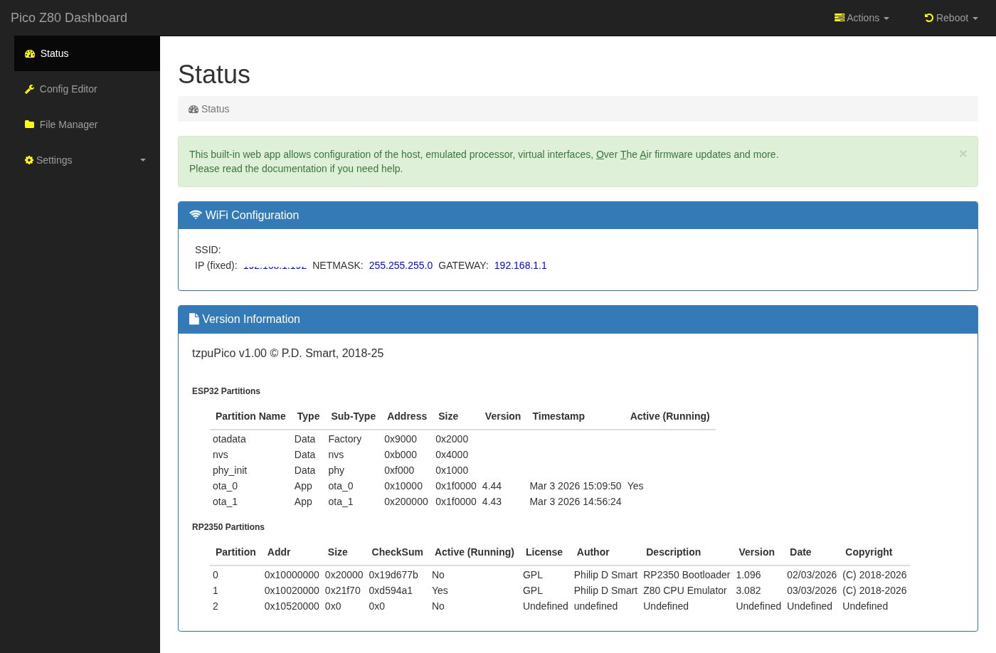
The landing page shows the board's live state across three panels:
- WiFi Configuration
- current SSID, assigned IP address, netmask, and gateway. The board name (tzpuPico) and copyright string are served as template variables by the ESP32 web server. - Version Information
- ESP32 partition table showing all OTA slots with type, sub-type, flash address, size, firmware version, build timestamp, and which slot is currently running. This makes it straightforward to confirm which firmware is active after an OTA update. - RP2350 Partitions
- the RP2350 flash partition table with partition number, address, size, checksum, active/running flag, license, author, description, version, build date, and copyright — giving a complete snapshot of the RP2350 firmware state alongside the ESP32 information.
- Actions menu
- Change Floppy Disk 1 / 2 — select a new DSK image file from the SD card and mount it in the virtual WD1773 floppy controller slot 1 or slot 2 without rebooting.
- Change QD Disk — swap the active QuickDisk image file on the fly.
- Reload RP2350 Config — send a reload command to the RP2350 over the ESP32–RP2350 UART; the RP2350 re-parsesconfig.jsonand re-applies the memory map and driver configuration without a full power cycle. - Reboot menu
- ESP32 — soft-reboot the ESP32 co-processor (restarts the web server and WiFi stack, RP2350 is unaffected).
- RP2350B — reset the RP2350 processor (re-runs the bootloader and reloads the active firmware slot, host CPU is paused during reset).
- Host — assert the host computer's reset line, rebooting the legacy computer in the Z80 socket without affecting the picoZ80 board itself.
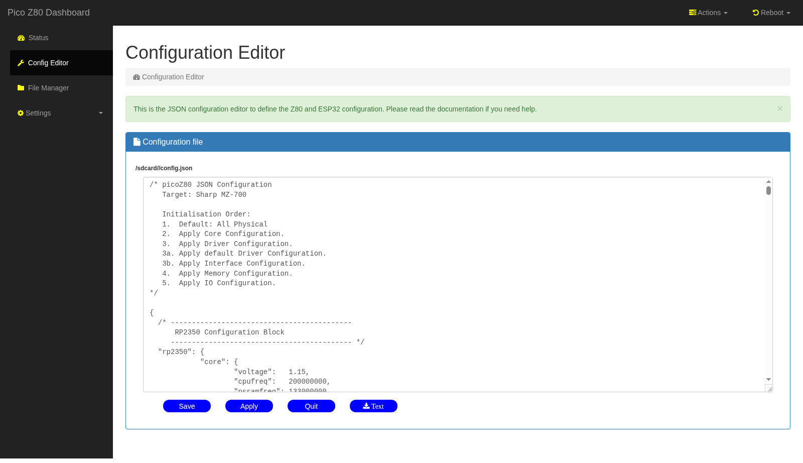
The Configuration Editor page gives full editting control over the jSON configuration file.
Change the configuration using the wysiwyg editor, save as needed and click Apply to reprocess the
configuration.
The SD card keeps automatic numbered backups of every saved configuration (
config.json;1,
config.json;2, … with the highest number being the most recent), so it is always possible to roll back to a
previous working configuration. Edited configurations are saved back to the SD card; clicking Apply or a "Reload" menu action
then sends a reload command to the RP2350 over the ESP32–RP2350 UART, causing the RP2350 to re-parse and re-apply the new configuration
and causes the ESP32 to parse and reload it's configuration.
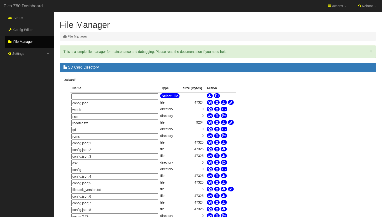
The File Manager provides a full web-based file browser for the SD card, providing a directory listing layout to view files
on the SD card.
It is intended for general SD card maintenance: uploading ROM images, floppy disk images (DSK), QuickDisk images (QD), RAM disk images, and web filesystem updates without needing to remove the card.
Each entry has action buttons to copy, delete, download, or edit text files, and a Select File upload button at the top allows new files to be transferred from the PC. Directory navigation allows descending into subdirectories such as
roms/, dsk/, qd/, and ram/.
Uploading tar or gzip files will automatically have the tar or gzip (or tar.gz) file unpacked and extracted in the current SD
directory.
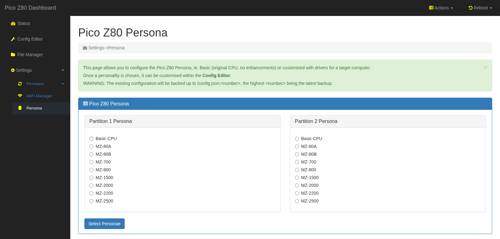
The Persona page configures the active machine personality independently for each of the two RP2350 firmware partitions. Each partition has its own column of radio buttons covering every supported Sharp MZ machine type:
- Basic CPU — bare Z80 emulation with no machine-specific drivers; useful for generic Z80 development.
- MZ-80A and MZ-80B — Sharp MZ-80 series (1Z-013A monitor ROM, MZ-80 keyboard, standard memory map).
- MZ-700 — Sharp MZ-700 with bank-switched VRAM, keyboard controller, and optional floppy/QuickDisk drivers.
- MZ-800 — Sharp MZ-800 with extended video modes and QuickDisk support.
- MZ-1500 — Sharp MZ-1500 with QuickDisk and optional floppy.
- MZ-2000, MZ-2200, MZ-2500 — later Sharp MZ series with high-resolution video and extended memory.
config.json to the SD card (backing up the current file first) and triggers a configuration reload. Because each firmware partition can hold a different persona, the board can be switched between, for example, an MZ-700 personality on partition 1 and an MZ-80A personality on partition 2 without any SD card editing.
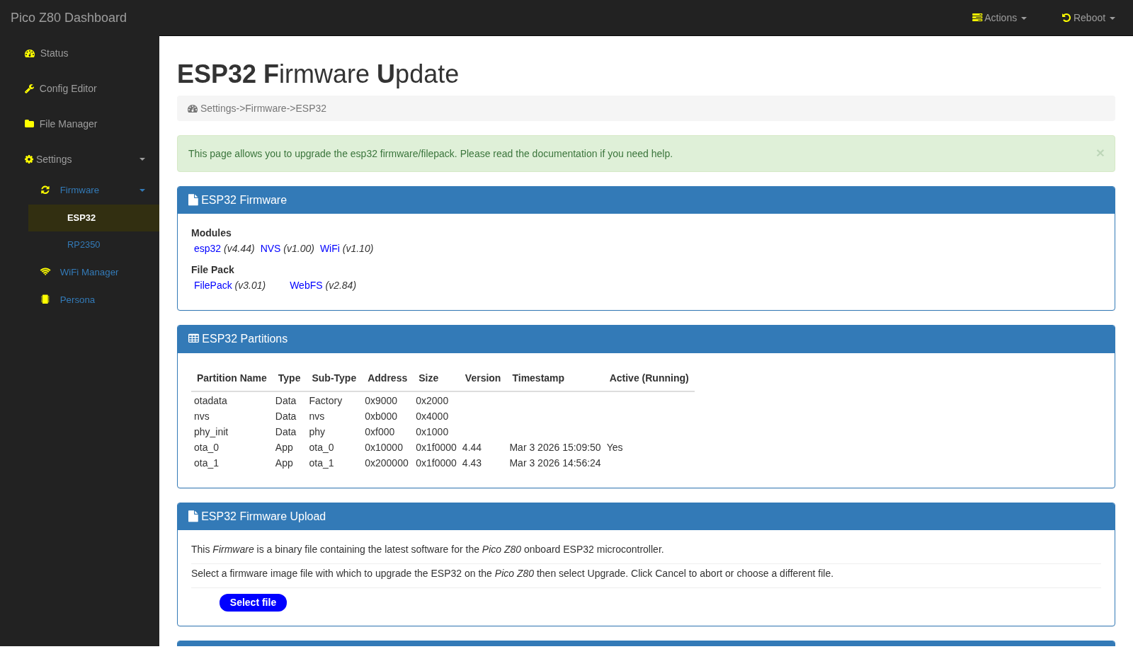
The ESP32 OTA page reports the full software inventory of the ESP32 before accepting a firmware upload:
- Modules panel
- shows the version of each ESP32 software component: the main ESP32 application, the NVS (non-volatile storage) library, the WiFi stack, the FilePack (web filesystem packager), and the WebFS (in-flash web file system). This makes it easy to confirm all components are consistent after an update. - ESP32 Partitions panel
- shows the full ESP32 OTA partition table (otadata, nvs, phy_init, ota_0, ota_1) with addresses, sizes, firmware versions, build timestamps, and which OTA slot is currently active (marked "Yes"). - ESP32 Firmware Upload panel
- accepts the ESP32 binary (.bin) produced by the ESP-IDF build. After upload the ESP32 reboots into the new firmware and the old slot is retained as a fallback. - FilePack Upload panel
- uploads a versioned FilePack archive to the SD card. A FilePack bundles all ESP32 static web assets (HTML, CSS, JavaScript templates, and ancillary files) into a single distributable archive. On upload the ESP32 unpacks the archive to the SD card web filesystem directory; any file being replaced is automatically renamed to include its previous version number (e.g.webfs→webfs.2.80), preserving the old version for rollback. This matches the VAX/VMS style versioning used elsewhere on the SD card, where each successive revision of an editable file is preserved with a numeric suffix:config.json;1,config.json;2, and so on — ensuring no edit is ever silently overwritten.
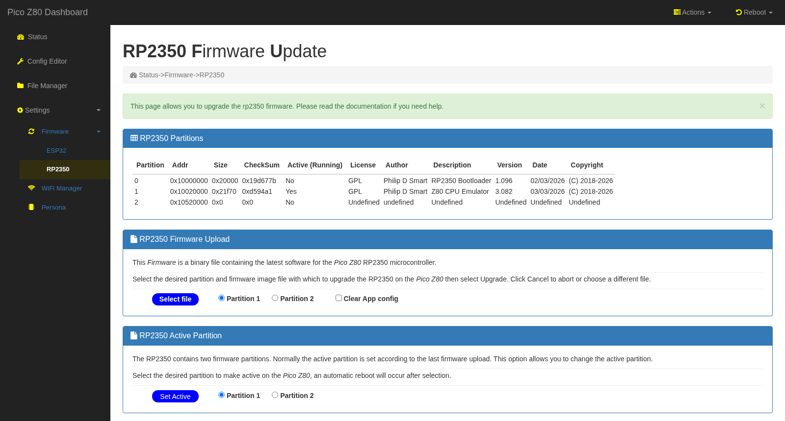
The RP2350 OTA page manages the two RP2350 firmware partitions:
- RP2350 Partitions panel
- lists all three partitions: partition 0 (Bootloader), partition 1 (first application slot, e.g. "Z80 CPU Emulator"), and partition 2 (second slot). Each row shows the flash address, size, checksum, active/running flag, license, author, description, version, and build date. The currently running partition is marked "Yes" in the Active column. - RP2350 Firmware Upload panel
- accepts a pure binary.binfirmware file fromfw/bin/. UF2 is not used here — application partitions are located at non-standard flash addresses that UF2 cannot express, so the OTA transfer uses raw binary. Use the Partition 1 / Partition 2 radio buttons to select the target slot, and optionally tick Clear App config to wipe the associated configuration partition (useful when upgrading to a firmware version with an incompatible config schema). The upload is verified by checksum before the new partition is activated. - RP2350 Active Partition panel
- independently switches the active partition without uploading new firmware. Selecting a partition here triggers an automatic reboot into the chosen slot — useful for switching between two pre-loaded firmware variants (e.g. Z80 and a test build) without any file transfer.
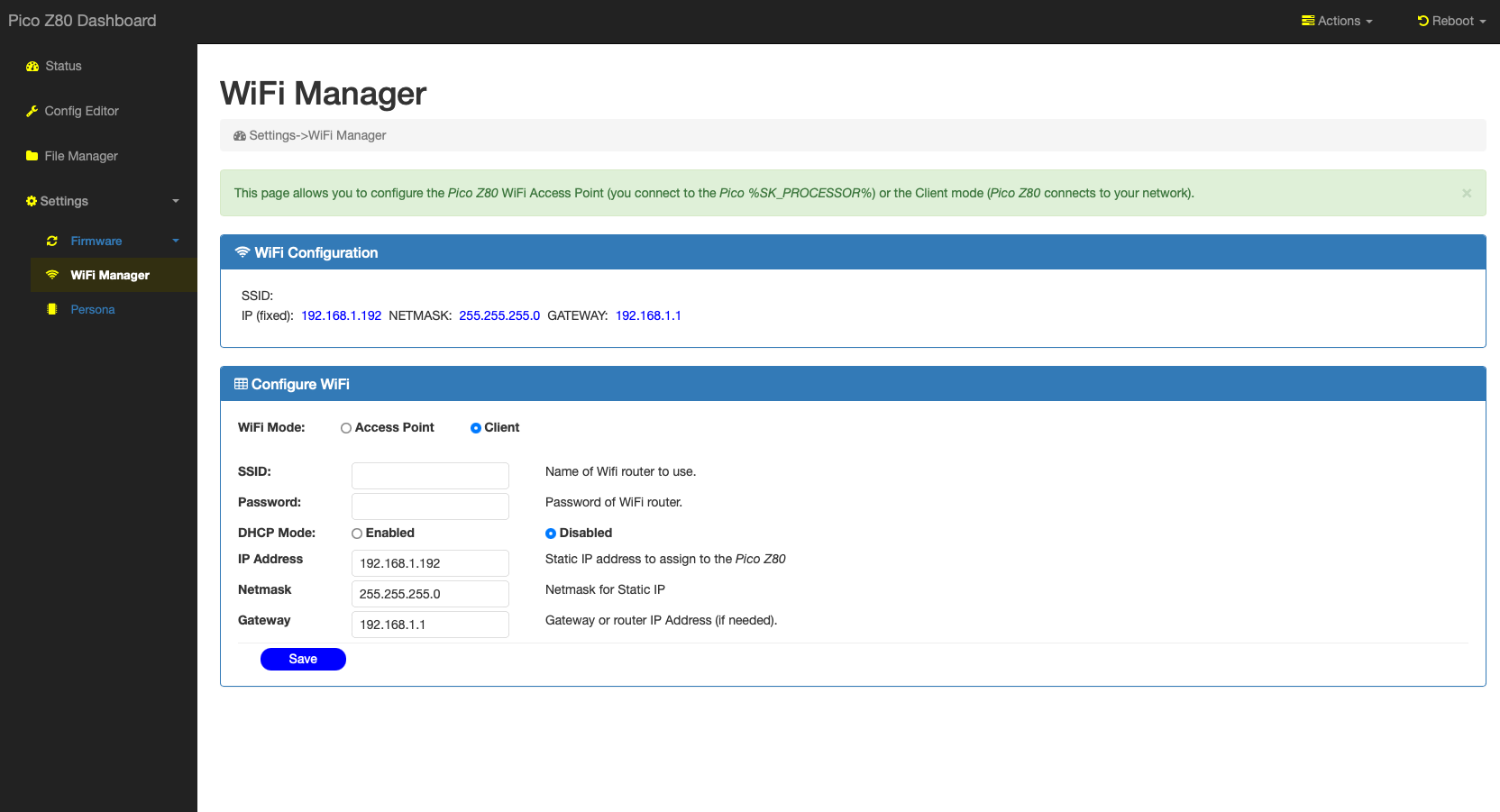
The WiFi Manager configures how the picoZ80 connects to a network. The top panel shows the currently active WiFi configuration (SSID, assigned IP, netmask, and gateway). The Configure WiFi form below it exposes all settings:
- WiFi Mode
- Access Point: the picoZ80 broadcasts its own SSID and you connect directly to it (useful during initial setup or when no infrastructure network is available). Client: the picoZ80 joins an existing WiFi network as a station. - SSID and Password
- the name and passphrase of the network to join (client mode) or to broadcast (AP mode). - DHCP Mode
- Enabled: the board requests an address from the network's DHCP server. Disabled: use a static IP, netmask, and gateway as entered in the fields below. A fixed IP is recommended so that the web interface address is always predictable.
Reference Sites
The table below contains all the sites referenced in the design and programming of the picoZ80.
| Site | Language | Description |
|---|---|---|
| RP2350 Datasheet | English | Official Raspberry Pi RP2350 technical reference and datasheet. |
| Pico SDK | English | Raspberry Pi Pico C/C++ SDK — build system and hardware abstraction used by the picoZ80 firmware. |
| Z80 CPU User Manual | English | Zilog Z80 CPU family user manual — bus timing, instruction set and signal descriptions. |
| ESP-IDF | English | Espressif IoT Development Framework used for the ESP32 co-processor firmware. |
| Sharp MZ Series | English | Community resource for Sharp MZ computer hardware, software and technical documentation. |
Manuals and Datasheets
The table below contains all the datasheets and manuals referenced in the design and programming of the picoZ80.
| Datasheet | Language | Description |
|---|---|---|
| RP2350 | English | Raspberry Pi RP2350 microcontroller datasheet. |
| ESP32-S3 | English | Espressif ESP32-S3 SoC datasheet — WiFi/BT co-processor on the picoZ80 board. |
| APS6404L PSRAM | English | 8MB SPI PSRAM datasheet — the main extended RAM used for memory banking. |
| W25Q128 Flash | English | Winbond 16MB SPI NOR Flash datasheet — stores firmware and ROM images. |
| TLV62590 | English | Texas Instruments 5V→3.3V synchronous buck converter powering the picoZ80 from the Z80 DIP-40 VCC pin. |
| CH334F | English | CH334F 4-port USB 2.0 hub controller — provides USB hub functionality for firmware updates. |
Project Preview
Early development previews of the picoZ80 project were shared on X (formerly Twitter). The following post shows the board running for the first time:
https://x.com/engineerswork1/status/1953171627065188841
Demonstration Videos
picoZ80 running RFS (ROM Filing System) — Demo 1
The picoZ80 installed in a Sharp MZ-700, running the ROM Filing System (RFS) persona. The video demonstrates the virtual disk and memory banking capabilities of the board.
Commercial Use Restriction
No commercial use permitted without express written permission.
The picoZ80 hardware design (schematics, PCB layout, KiCad files), firmware, and all associated software are made available for personal, educational, and non-commercial use only. No part of this design — including but not limited to the PCB artwork, bill of materials, firmware binaries, source code, or documentation — may be used, reproduced, manufactured, sold, or incorporated into any commercial product or service without the express written permission of the author (Philip D. Smart).
To request a commercial licence or discuss permitted uses, please contact the author via the eaw.app website.
Credits
The picoZ80 project builds on the work of several individuals and open-source projects. Their contributions are gratefully acknowledged.
- Manuel Sainz de Baranda y Goñi
Author of the Z80 C-language Z80 CPU emulator library (github.com/redcode/Z80). This high-accuracy, cycle-accurate Z80 emulator core is used by the picoZ80 firmware when running Z80 instructions internally on the RP2350, providing precise flag behaviour and undocumented opcode support. The library is used under the terms of the GNU General Public License v3. - Raspberry Pi Ltd
Authors of the Pico SDK and RP2350 hardware. The PIO assembler, C SDK, CMake toolchain integration, and RP2350B silicon make the cycle-accurate bus interface possible. - Espressif Systems
Authors of the ESP-IDF framework and ESP32 hardware. The ESP32 co-processor, WiFi stack, OTA library, and NVS storage framework underpin the web management interface. - Philip Smart
Hardware design (KiCad schematics and PCB layout), RP2350 PIO firmware, ESP32 web application, JSON configuration system, Sharp MZ machine persona drivers, and all project documentation. - Grok (xAI)
AI assistant that provided valuable help during PIO state machine debugging — particularly in diagnosing timing edge cases and cycle-accurate bus interaction issues in the RP2350 PIO programs. - Claude (Anthropic)
AI assistant contributing to this project across multiple areas: authoring and structuring the project documentation, analysing the FSPI/UART interface between the RP2350 and ESP32 and providing firmware improvement recommendations, and ongoing firmware development assistance.
Licenses
The picoZ80 project is composed of several components, each covered by its own licence:
In short: the firmware and software you build from this project's source code are open-source under the GPL v3; the hardware designs are open-source under the CERN-OHL-P v2; third-party libraries retain their own licences as listed above.
| Component | Licence |
|---|---|
| picoZ80 RP2350 firmware (PIO, C sources) | GNU General Public License v3 |
| picoZ80 ESP32 firmware and web interface | GNU General Public License v3 |
| Z80 CPU emulator library (Manuel Sainz de Baranda y Goñi) | GNU General Public License v3 |
| KiCad hardware design files (schematics, PCB) | CERN Open Hardware Licence v2 — Permissive (CERN-OHL-P v2) |
| Raspberry Pi Pico SDK | BSD 3-Clause |
| ESP-IDF framework | Apache License 2.0 |
| Bootstrap 4 (web interface) | MIT License |
The GNU General Public License v3
Copyright © 2024–2025 Philip Smart and contributors.
This program is free software: you can redistribute it and/or modify it under the terms of the GNU General Public License as published by the Free Software Foundation, either version 3 of the License, or (at your option) any later version.
This program is distributed in the hope that it will be useful, but WITHOUT ANY WARRANTY; without even the implied warranty of MERCHANTABILITY or FITNESS FOR A PARTICULAR PURPOSE. See the GNU General Public License for more details.
You should have received a copy of the GNU General Public License along with this program. If not, see https://www.gnu.org/licenses/.
The full licence text is also included in the repository as
LICENSE.