 tranZPUterFusionX
Overview
The tranZPUterFusionX is a spinoff concept from the tranZPUter series. It shares the same purpose, to replace the physical Z80 in a Sharp or similar system and provide it with features such as faster CPU, more memory, virtual devices,
rapid application loading from SD card and by using a daughter board, better graphics and sound.
The FusionX board can also be used to power alternative CPU's on the host for testing, development and to provide a completely different software platform and applications. It can use the underlying hosts keyboard, monitor, I/O and additionally better graphics and sound provided by the FusionX.
It shares similarities with the tranZPUterFusion but instead of realising it in hardware via an FPGA it realises
it in software as an application. This is made possible by a SOM (System On a Module), not much bigger than an FPGA device yet provides an abundance of features, ie. dual-core 1.2GHz Cortex-A7 ARM CPU, 128MB RAM, 256MB FlashRAM, Wifi, HD Video, SD Card, USB port and runs the Linux operating system.
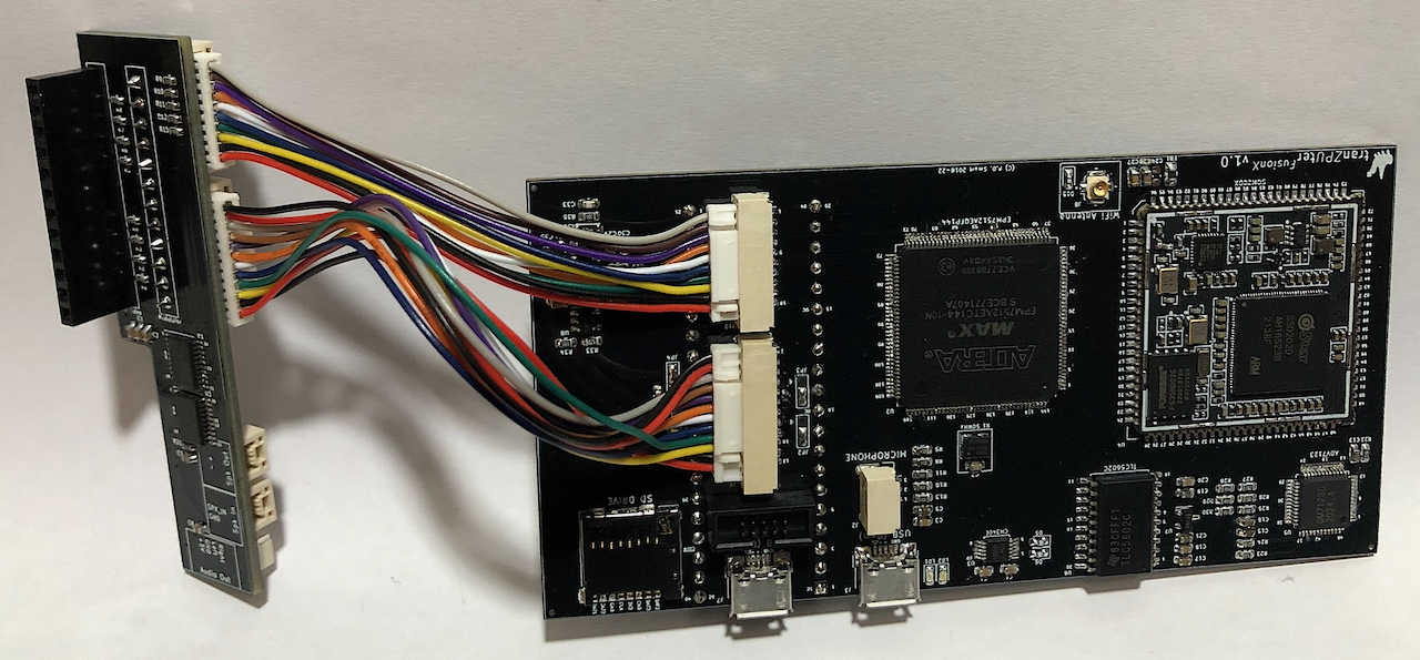
Using the same base design as the tranZPUterFusion it incorporates a CPLD to interface the Z80 host to the SOM and provide cycle accurate Z80 timing. The SOM interfaces to the CPLD via a 72MHz SPI channel and an 8bit bus to query signal status and initiate Z80 transactions.
In Z80 configuration, a Linux Kernel driver instantiates a Z80 emulation which realises a Z80 CPU in software which in turn can command and control the host system. The kernel driver along with a controlling application
can provide a wealth of features to the host through this mechanism. The SOM is also connected to an SD Drive and USB 2.0 port so there is no limit to features which can be provided.
Like the tranZPUterFusion, the tranZPUterFusionX can provide enhanced video and sound to the host. The SOM incorporates dual DAC audio and a 2D GPU with configurable resolutions switched onto the hosts video and audio outputs under software control.
The FusionX board is ideal for any developer wanting to physically program and interact with retro hardware using a Linux platform with Wifi and USB/Serial port connectivity.
To most retro users, in the early stages of FusionX development, the board wont have much use. As the project matures, a board can be obtained and installed into the Z80 socket of their Sharp or simlar Z80 based system (providing there is sufficient room to accommodate this board) and utilise the upgraded featues, such as:
- Original host specifications
- the machine behaves just as though it had a physical Z80 within. There might be slight differences in the Z80 functionality as it is implemented in software but the Z80 hardware timing is accurate. - Accelerator
- the Z80 can run at much higher speeds due to the abundance of memory and 1.2GHz dual-core processor, which would typically see performance upto that of a 500MHz Z80. - Emulation
- emulation of all the Sharp MZ series machines, experiencing it through the host system keyboard, monitor and I/O. - Graphics
- all original Sharp MZ graphics modes, regardless of host, including additional resolutions upto HD are available through GPU configuration and these can be selected and programmed on the host in languages such as Basic. - Sound
- the host will have access to the stereo DAC converters, which can playback 48KHz CD quality sound or emulate the SN76489 or basic bit/timer sound of the Sharp series. Sound recording is also possible via the Mic input. - Processors
- there are many software CPU implementations which can be ported to run on this platform, for example the ARM platform CPU emulations of the BBC PiCoPro can readily be ported. This in turn allows the potential for other machines, using the SOM advanced graphics and sound as necessary, allow emulations of machines such as the BBC to run on this Sharp host. - Linux
- using the host keyboard, speaker, monitor etc, a full blooded version of Linux, including Wifi, can be utilised at the host console.
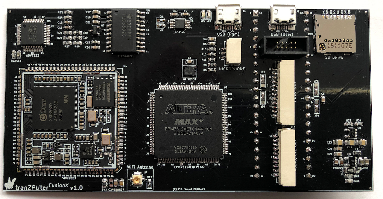
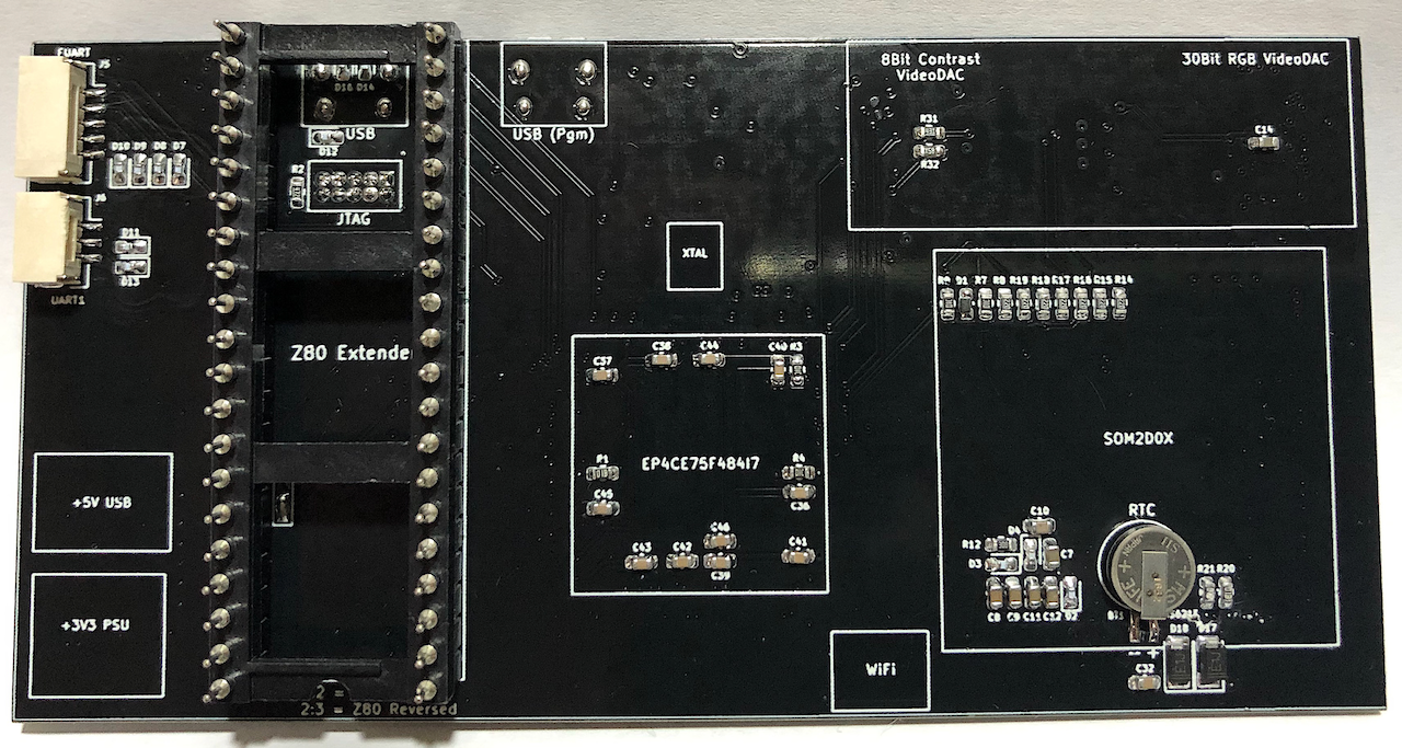
Hardware
Version 1.0 is the first official release of the tranZPUterFusionX design.
The FusionX board builds on a tried and tested Z80 host interface using the Altera 7000A MAX CPLD device. The CPLD not only interfaces the 5V Z80 host signals to the 3.3V signals on more recent devices, it also embeds the logic to perform accurate Z80 timing using a 50MHz clock to
sample the Z80 host clock and activate signals according to the published Z80 state diagrams.
In addition the FusionX includes a SigmaStar System-On-a-Module, this is a small 29mmx29mm stamp device which incorporates a dual-core Cortex-A7 CPU, 128MByte DRAM, 256MBytes FlashNAND and a Wifi transceiver. The SigmaStar SOM is capable of outputting 2D Graphics in an RGB 888 format
with selectable resolution upto HD format. It is also capable of stereo audio DAC output at 48KHz. Click to view the full SigmaStar product brief.
Using the experience gathered on the tranZPUter SW-700, a 30bit Video DAC is chosen to render the SigmaStar SOM video rather than a 2R-R ladder and additionally an 8bit DAC is included for rendering monochrome monitor contrast levels to cater for colour shading on monochrome CRT
monitors as found in the MZ-80A/MZ-2000.
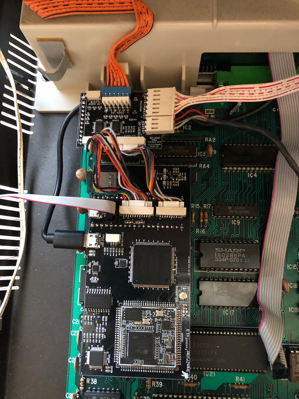
The hardware design centers on a main circuit board which holds all the primary circuitry and a number of daughter boards, each daughter board dedicated to one host (ie. MZ-700, MZ-80A, MZ-2000). The daughter board intercepts the host video/audio subsystem and supports switching
of the host video/audio and the mainboard video/audio to the monitor/speaker of the host. The mainboard can be used without daughter boards, the latter are only used when the SOM Video/Audio is required.
This section outlines the mainboard schematics and circuit board design of the tranZPUterFusionX.
Schematics
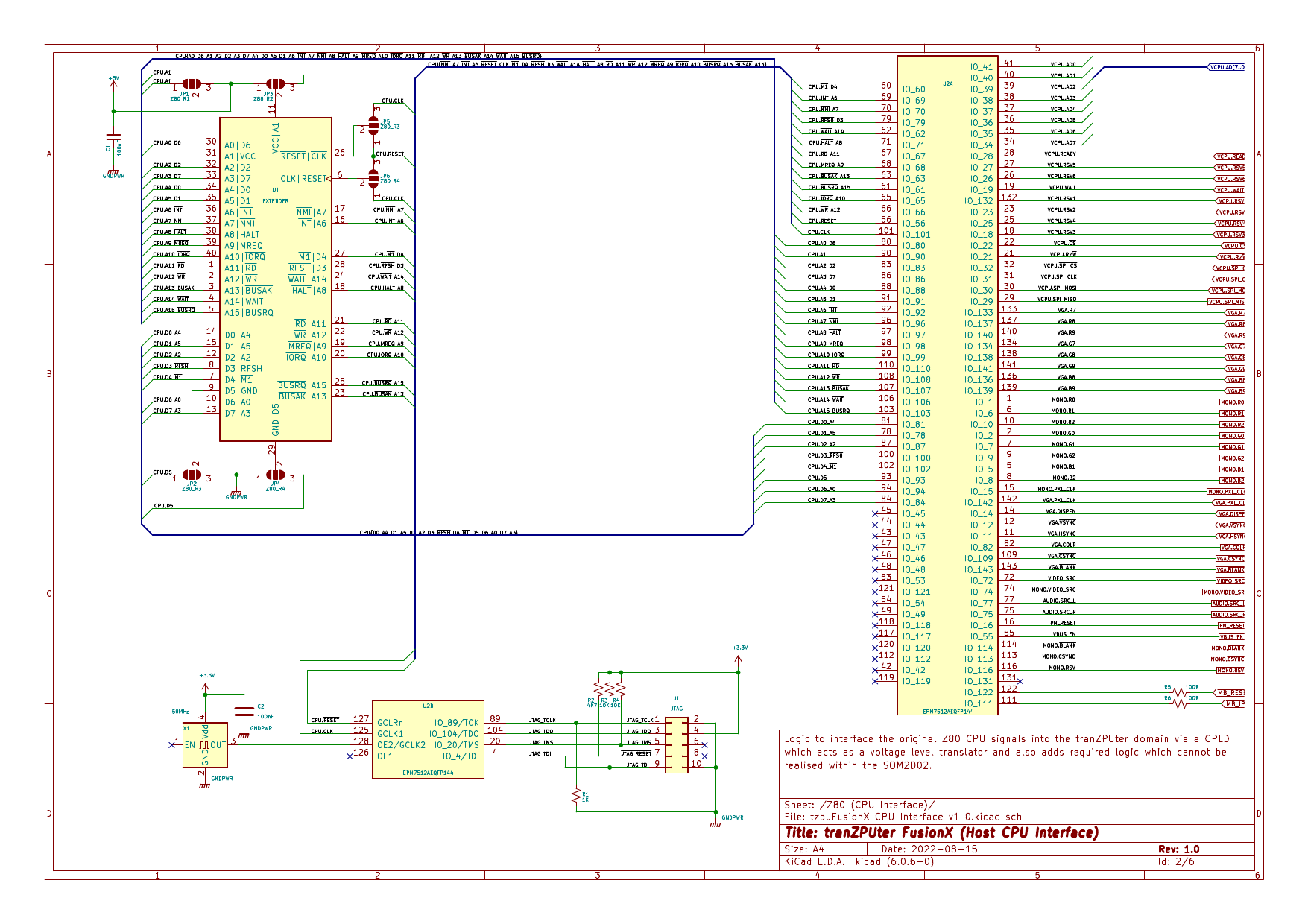
Schematic 1 - Z80 Host socket to CPLD
The schematic interfaces the Z80 to the CPLD. The CPLD is 5V tolerant and operates internally at 3.3V. The outputs are selected as Low Voltage TTL meaning a '1' is represented by 3.3V as opposed to 5V in the host system. The specifications of 5V TTL see the switching threshold at approx 2.4V,
thus the CPLD is able to drive 5V circuitry and with sufficient drive current, 25mA per pin.
The CPLD internal state machines are clocked by an external 50MHz oscillator, this allows for adequate sampling and state change for a typical 1MHz - 6MHz Z80 host.
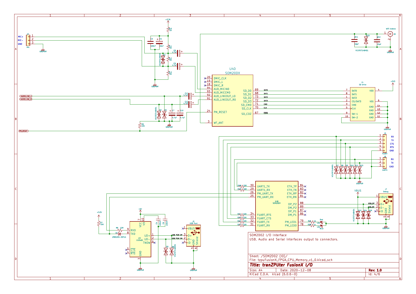
The SOM is rich in peripherals and this circuit interfaces some of them for use in the FusionX, these include:
- Stereo Audio Microphone input
- a digital microphone input is also available but the pins are used in the CPLD interface. - Stereo Audio DAC output
- dual digital to analogue converters for sound output which can be clocked at 48KHz. - WiFi Antenna
- a SSW101B 20/40MHz IEEE 802.11 b/g/n/e/l/n/w WiFi transceiver operating in the 2.4GHz band with a 500M range. The SOM also includes a 100MHz ETH PHY but this is not used in this design as hard wired ethernet is not practical for a board which is sited inside a retro machine. - USB Serial
- when running Linux, the console is presented on a UART serial device. This serial device is converted into USB for ease of use to view and connect with the Linux console. - USB
- a Linux connected USB port allowing for device expansion, such as additional storage, mice etc. - Fast UART
- high speed full duplex with hardware handshake UART. - UART
- standard 2 pin UART operating upto 500KHz. - SD Card
- the SOM has inbuilt FlashNAND so can accomodate a simple Linux filesystem, addition of an SD card allows for greater storage of Host applications and Linux utilities. An SD card also makes for ease of upgrades as the SOM will auto upgrade when a suitably prepared SD card is present on boot.
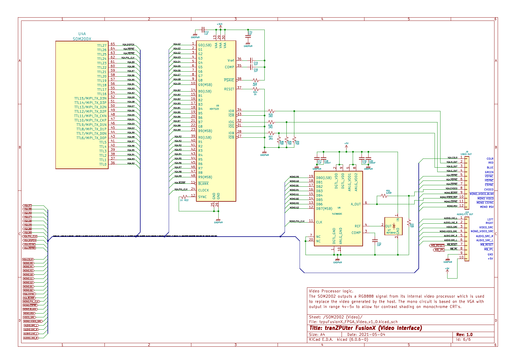
The SOM outputs TTL RGB with 8bits per colour. This is interfaced to a 30bit VideoDAC with the lowest 2 bits, per colour, controlled by the CPLD.
In addition, in order to drive the internal monochrome monitors of the Sharp MZ-80A/MZ-80B/MZ-2000 an 8bit VideoDAC is added which outputs a video signal in the range 4V-5V using a 332 RGB colour input, the colour input being the MSB of the SOM 888 TTL output. I term this the Contrast
DAC, as it is sending the video signal with colour information as a voltage controlled contrast signal which presents itself on the monitor as differing contrast levels, thus simulating colour as grey levels.
In order to get true black, the CPLD creates a blanking signal, MONO.BLANK, which is paired with a MUX 0V clamp on the daughter board which drives the monochrome monitor, this sees the RGB332 as 0V when 00000000 is present, then varying between 4.01V-5V when non-zero.
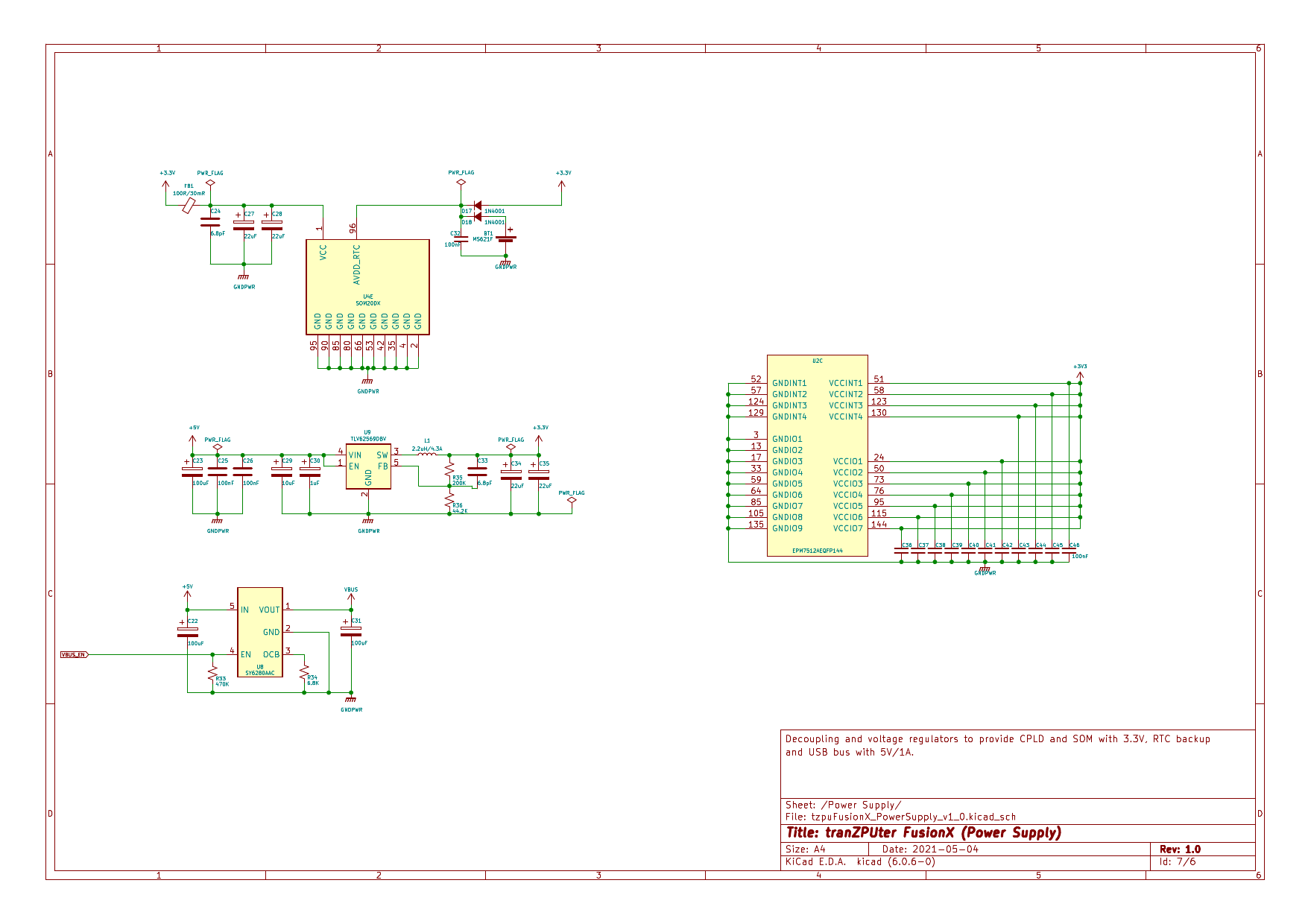
The power supply, for the SOM and CPLD, converts the 5V present on the Z80 socket into 3.3V using a high efficiency buck converter. This is necessary to minimise heat and provide maximum current to the SOM/CPLD.
Additionally, a software controlled USB power switch is installed to enable (and reset if required) +5V power to the USB expansion port.
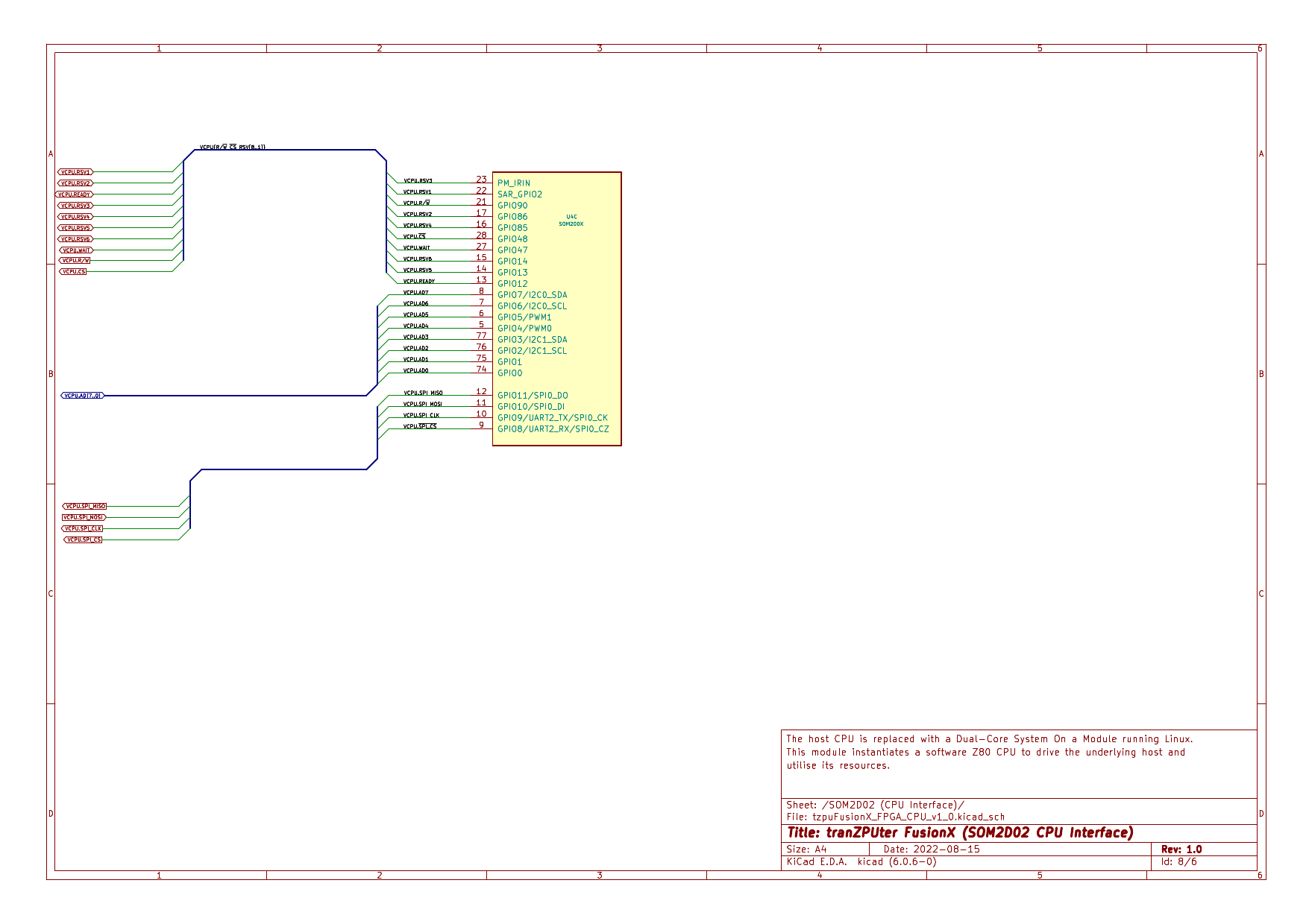
The final schematic is the interface between the SOM and the CPLD. Originally this was going to be a bi-directional 16bit bus with Read/Write and Strobe signals but after testing, the setup time for a 16bit signal with tri-state switching was much slower than an SPI connection
due to the GPIO register layout and operation within the SOM and the speed of the I/O operations within the SOM.
The solution used is to have a bidirectional 72MHz SPI bus between the SOM and CPLD for transmitting Z80 transaction requests and an 8bit read only parallel bus for more rapid reading of Z80 Data and seperate Z80 state information.
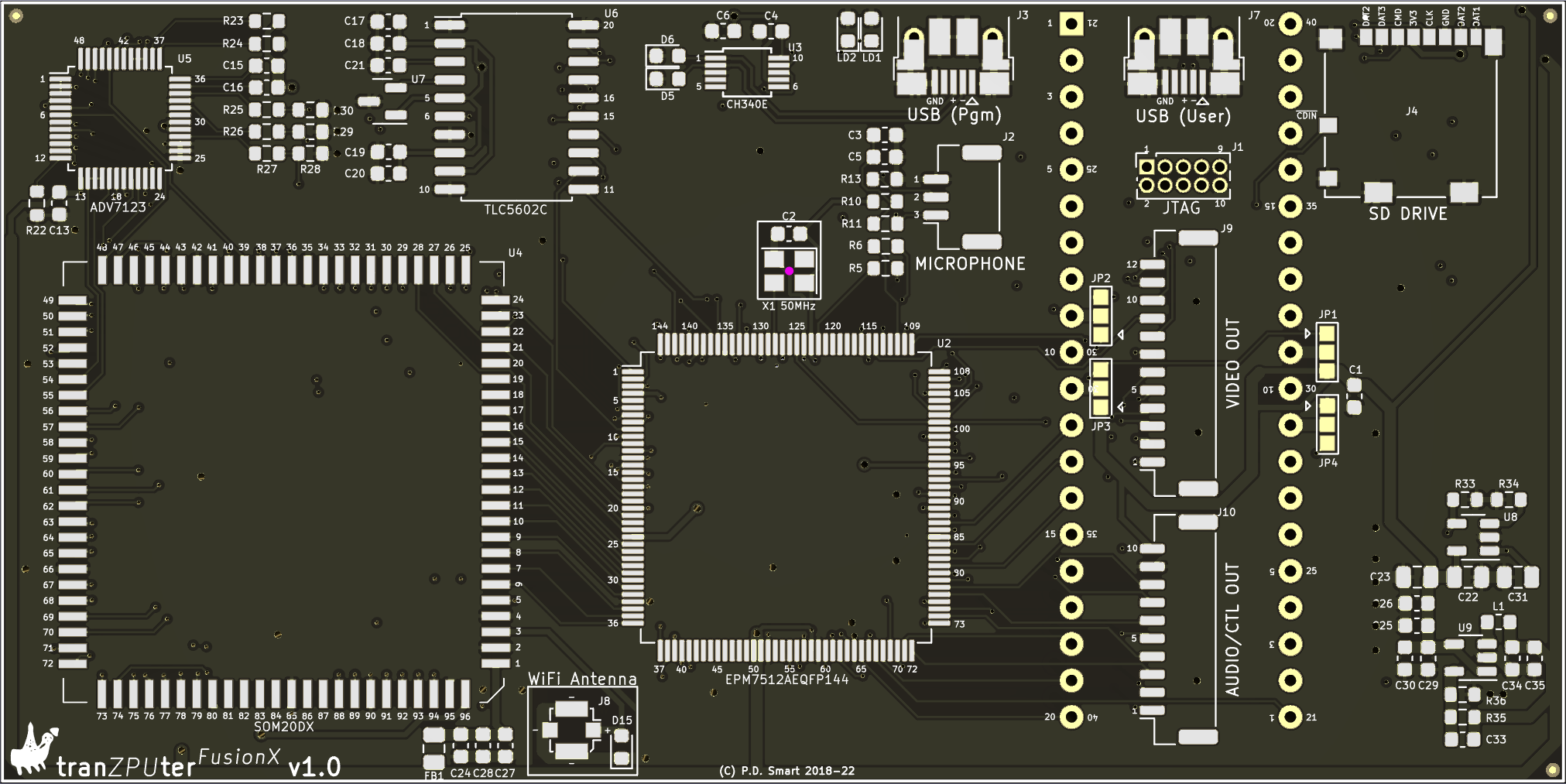
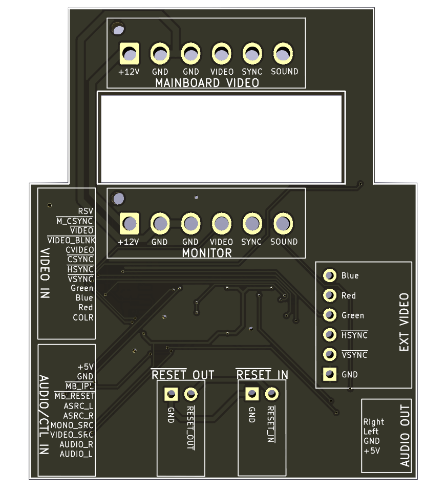
PCB
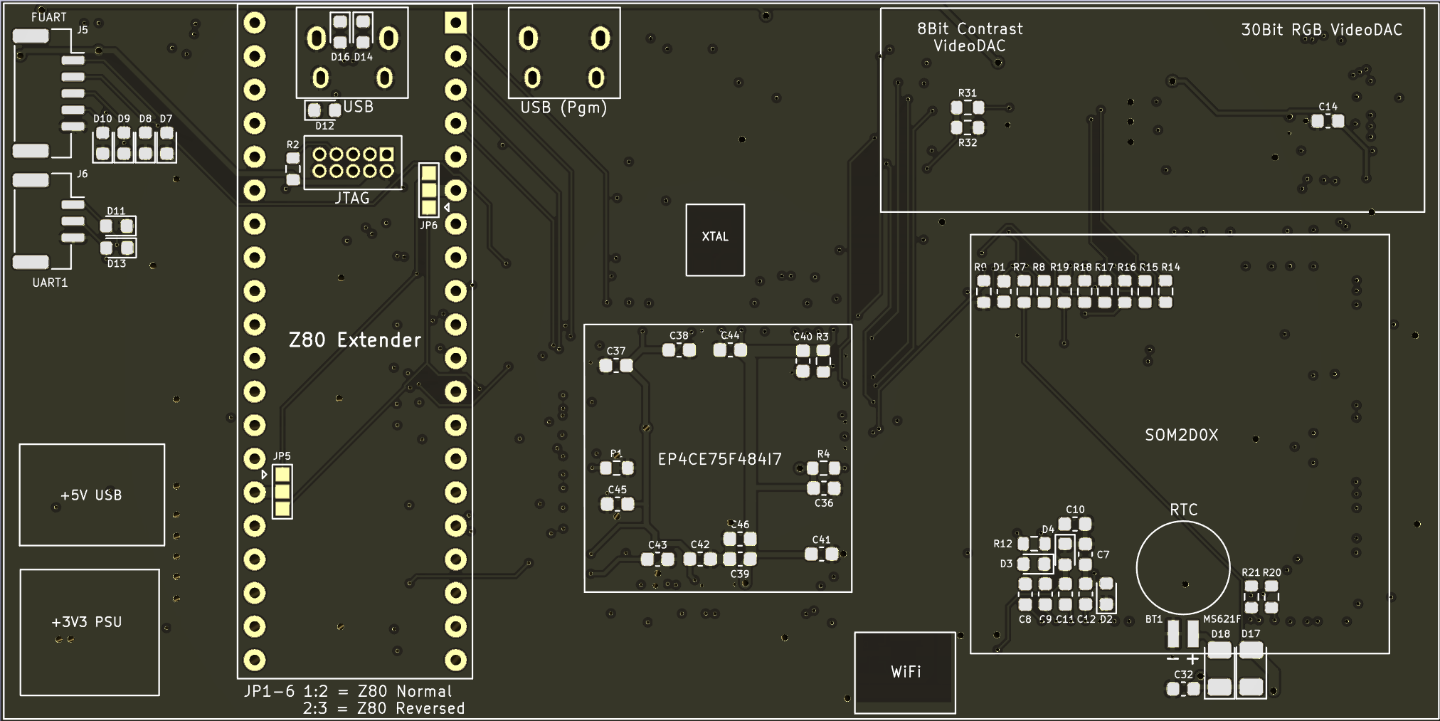
The PCB was designed with minimum size as a primary requirement for the various machines in which it would be installed. It also had to be compatible with the tranZPUterFusion for interchangeability.
A major concern was heat dissipation as the PCB, when installed within an MZ-700 is very close to existing motherboard components which give off a lot of heat with no air circulation in a sealed compact housing. This meant active components couldnt be sited on the PCB underside
as heat generation would lead to instability and failure, which in turn led to an increase in the final PCB size.
The smallest components which could be manually assembled where used, ie. 0402/0603 passive devices and 0.5mm IC pitch spacing to reduce overall size and a 4 layer stackup selected to fit all required components.
PCB Top Overview
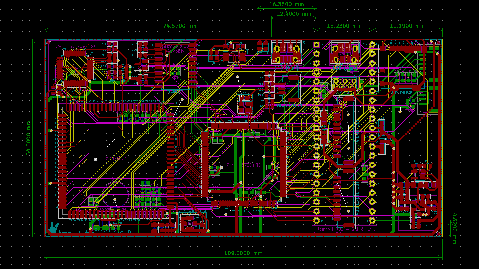
Click here to view an interactive PCB component placement diagram and Bill of Materials.
Software
Under construction.
Linux
Under construction.
Z80 Emulator
Under construction.
Daughter Boards
The tranZPUter series was initially developed in the Sharp MZ-80A and was primarily a Z80 replacement. As the concept evolved and the tranZPUter SW-700 was developed for the MZ-700 it became more of an integral component of the machine, offering original and upgraded Video and Audio capabilites by intercepting and routing existing signals.
After significant developments on the tranZPUter SW-700 it became desirable to port it back to the MZ-80A and MZ-2000 but these machines had different CPU orientation and signal requirements, ie. driving an internal and external monitor. This requirement led to the concept of daughter boards, where a specific board would be designed and developed for
the target host and would plug into the tranZPUter SW-700 card. Ideally I wanted to port the SW-700 to an MZ-800/MZ-1500 and X1 but the size of the card and orientation of the Z80 was a limitation.
During the design of the tranZPUterFusionX one of the main requirements was to make the board small, the Z80 orientation changeable and also compatible with the tranZPUterFusion so that it could fit many machines and be interchangeable. As the SW-700 also interfaced to the Video and Audio of the machines
and each was quite different, it became apparent that the tranZPUterFusionX needed to include a concept to allow different video/audio interfaces according to the targetted host. This concept was realised via daughter boards. Two connectors would link the tranZPUterFusionX to a daughter board which would be
specifically designed for the intended host.
The daughter boards would be responsible for switching and mixing video/audio signals and to drive internal monitors and provide the correct input and output connectors for ease of installation.
Currently three daughter boards have been developed, for the MZ-700, MZ-80A and MZ-2000 and more will follow as the design progresses.
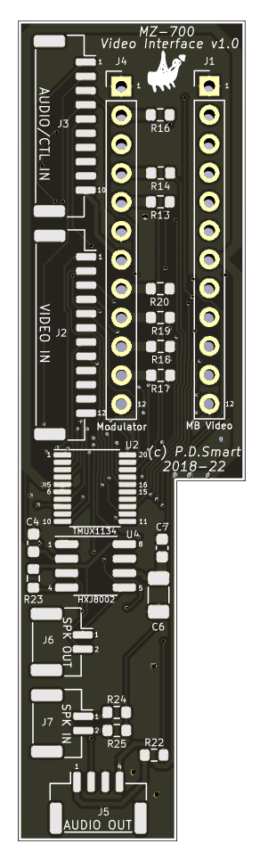
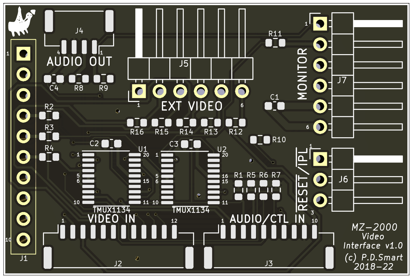
MZ-700 Daughter Board
The purpose of the MZ-700 daughter board is to interface the video/audio circuits of the FusionX board with those of the MZ-700. It is designed to be inserted into the mainboard modulator output and the modulator connector in turn connected to the daughter board. This allows the MZ-700 to be used with a standard monitor and the video output
is switched between the MZ-700 and FusionX under control of the FusionX.
The original sound circuity of the MZ-700 drives a speaker directly and in order to inject FusionX audio into the MZ-700 speaker, the mainboard speaker output is routed to the daughter board, level converted and switched under control of the FusionX. The FusionX offers stereo sound so this is selectively switched/mixed with the
original MZ-700 sound and fed to a Class D amplifier which then drives the internal speaker. Line level stereo output is achieved via an additional 4pin connector and used as required.
This setup allows for Linux or emulated machines, whilst running as an application on the FusionX, to output their sound to the internal speaker.
MZ-700 Video Interface Schematic
The MZ-700 daughter board consists of three 4way SPDT analogue switches to route video and audio signals under FusionX control and a Class D power amplifier.
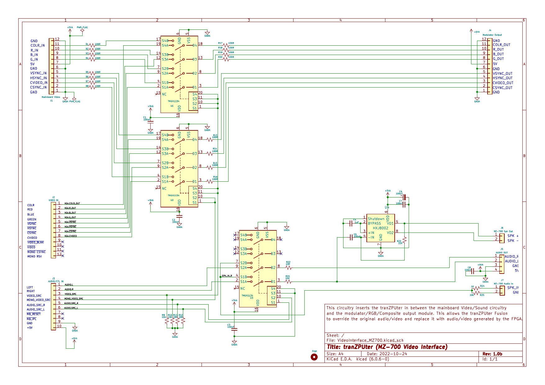
The MZ-700 daughter board PCB is small and compact due to the space restrictions. It has to fit onto the existing modulator connector and within the available free space.

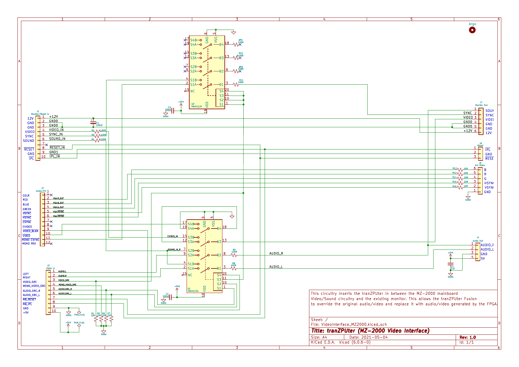
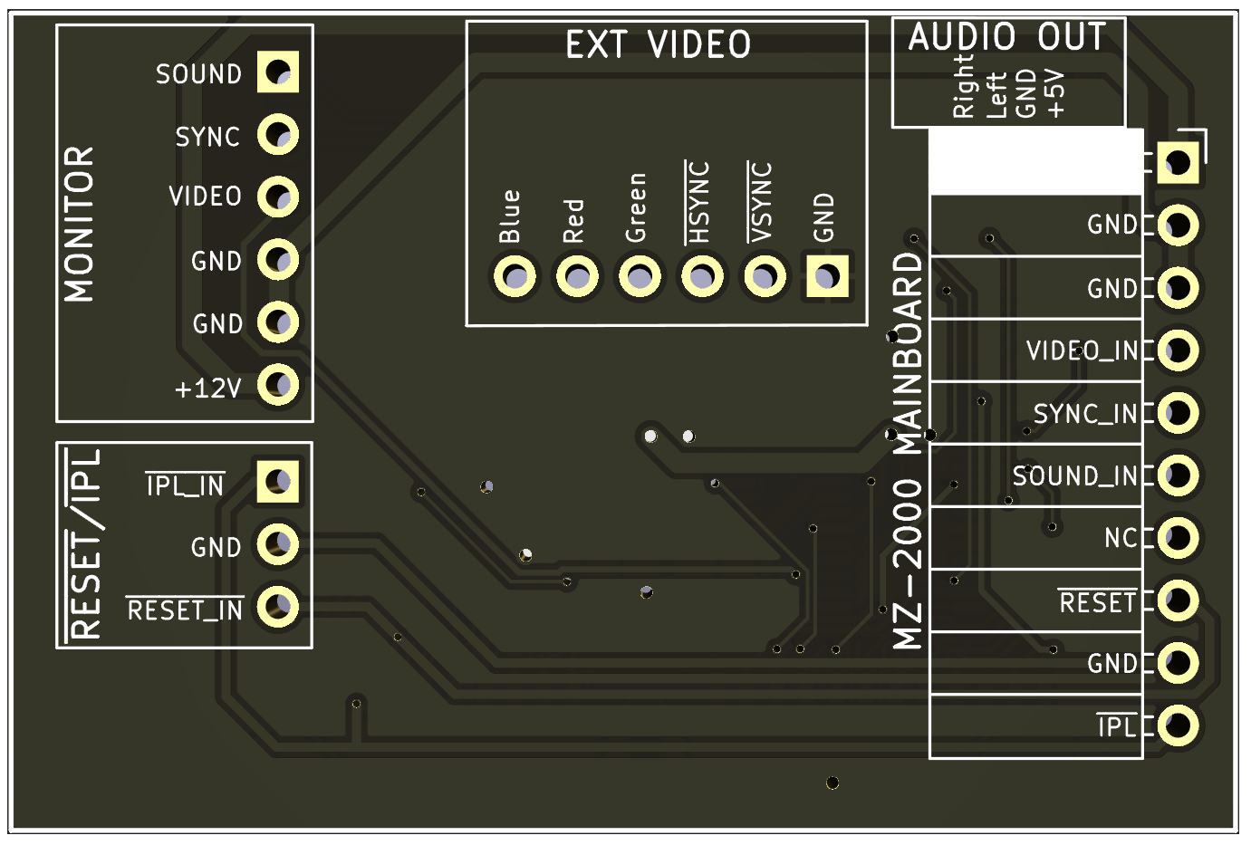
MZ-2000 Daughter Board
The purpose of the MZ-2000 daughter board is to interface the video/audio/reset circuits of the FusionX board with those of the MZ-2000. The MZ-2000 has an internal monochrome CRT, external RGB video and internal Audio with an amplifier on the monochrome CRT control board.
The daughter board is designed to be inserted simultaneously into the mainboard monitor and IPL connectors. It presents all the required connectors to connect the IPL/RESET switches, internal monitor and external monitor on the same board.
The IPL and RESET inputs are intercepted on the daughter board and sent to the FusionX as the MZ-2000 operates in different modes dependent on which RESET key is pressed during a Z80 Reset.
The video signals from the mainboard are switched with the FusionX video monochrome signals and sent to the internal CRT monitor. This allows for original video output on the CRT monitor or advanced FusionX text and graphics, resolution subject to the timing constraints of the monitor.
The FusionX RGB output is routed to the MZ-2000 external RGB video socket allowing for upto full HD external colour video display.
The sound circuity of the MZ-2000 is sent to an audio amplifier on the CRT monitor. This signal is intercepted and switched with the FusionX audio which then drives the CRT monitor amplifier. Line level stereo output is achieved via an additional 4pin connector and used as required.
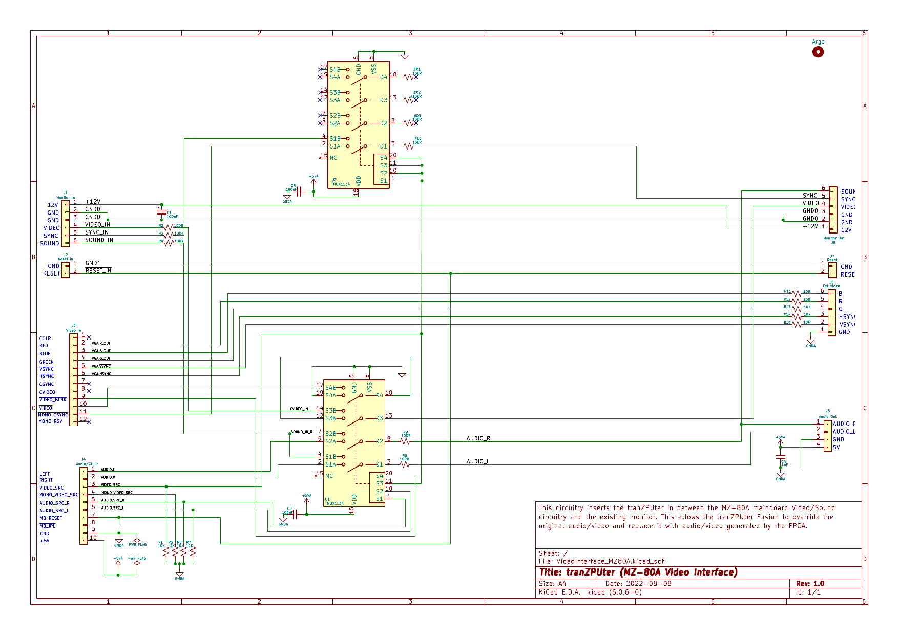
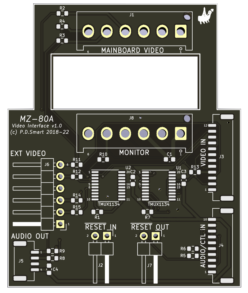
MZ-2000 Video Interface Schematic
The MZ-2000 daughter board consists of two 4way SPDT analogue switches to route video and audio signals under FusionX control. One SPDT switch is used for creating pure black in the modified video signal generated on the FusionX board.
The MZ-2000 daughter board PCB is small and compact due to the space restrictions and the number of connectors it must carry. It plugs into the mainboard monitor/IPL male connectors and then presents new CRT monitor, external Video and IPL/RESET switch connectors for all the exising internal cabling.
MZ-80A Daughter Board
The purpose of the MZ-80A daughter board is to interface the video/audio/reset circuits of the FusionX board with those of the MZ-80A. The MZ-80A has an internal monochrome CRT, cutouts for and external RGB video socket and internal Audio with an amplifier on the monochrome CRT control board.
The daughter board is designed to plug into the vertical mainboard CRT video connector with a gap so that the data cassette connector can be simultaneously connected. The gap is necessary as the CRT video connector sits close to the rear sidewall so the daughter board must extend forwards towards the keyboard.
It presents all the required connectors to connect the RESET switch (both in and out), internal monitor and external monitor on the same board.
The RESET input is intercepted on the daughter board and sent to the FusionX. Technically it isnt needed as the FusionX samples the Z80 Reset which is based on this input, but it can be useful, for example, detecting requests to reboot the SOM (double press) rather than the MZ-80A circuitry.
The video signals from the mainboard are switched with the FusionX video monochrome signals and sent to the internal CRT monitor. This allows for original video output on the CRT monitor or advanced FusionX text and graphics, resolution subject to the timing constraints of the monitor.
The FusionX RGB output is routed to the MZ-80A external RGB video socket (if installed) allowing for upto full HD external colour video display.
The sound circuity of the MZ-80A is sent to an audio amplifier on the CRT monitor. This signal is intercepted and switched with the FusionX audio which then drives the CRT monitor amplifier. Line level stereo output is achieved via an additional 4pin connector and used as required.
MZ-80A Video Interface Schematic
The MZ-80A daughter board consists of two 4way SPDT analogue switches to route video and audio signals under FusionX control. One SPDT switch is used for creating pure black in the modified video signal generated on the FusionX board.
The MZ-80A daughter board PCB is small and compact with a large punchout to enable connection with the mainboard CRT connector and thru connection of the data cassette signal connector. It plugs into the mainboard CRT monitor connector and then presents new CRT monitor, external Video and RESET In/Out switch connectors to be used with all the exising internal cabling.
Reference Sites
The table below contains all the sites referenced in the design and programming of the tranZPUterFusionX
| Site | Language | Description |
|---|---|---|
| Z80 Emulation | English | A highly accurate Z80 Emulation written in C, the heart of the FusionX. |
| WhyCan Forum | Chinese | Invaluable Forum with threads on SigmaStar products. |
| SSD20X System Development Manual | Chinese | System development manual for the SSD20X CPU. |
| SigmaStarDocs | Chinese | SDK and API development manual. |
| SOM2D0X Beginners Guide | Chinese | Beginners Guide to the SOM2D0X. |
| CivetWeb Users Manual | English | User Manual for the CivetWeb Embedded Web Server. |
Manuals and Datasheets
The table below contains all the datasheets and manuals referenced in the design and programming of the tranZPUterFusionX
| Datasheet | Language | Description |
|---|---|---|
| ADV7123 | English | Original 5V 30bit VideoDAC (discontinued) |
| GM7123 | Chinese | Chinese 3.3V version of the ADV7123 30bit VideoDAC converter. |
| CH340E | Chinese | USB to Serial UART converter. |
| EPM7512AEQFP144 | English | Altera 512 MacroCell 5V tolerant CPLD. |
| HXJ8002 | English | Class D power amplifier. |
| SOM2D01 | English | SigmaStar SOM Datasheet (original model). |
| REF3040 | English | Precise 4V reference voltage generator. |
| SY6280 | English | Power distribution switch, used for enabling and supplying USB Bus power. |
| TLC5602C | English | 8bit VideoDAC converter. |
| TLV62569 | English | High efficiency Buck Converter. |
| TMUX1134 | English | Precision SPDT Analogue switch (Mux). |
| VCUT0714BHD1 | English | ESD Protection Diode. |
| USB Programmer | English | SigmaStar USB Programmer for SSD202 Processor. |
| SSD201 HW Checklist v10 | English | SigmaStar SSD201 Hardware Checklist. |
| SSD202D Reference v04 | English | SigmaStar SSD202 CPU Reference Manual. |
| SOM2D02_Pinout | English | SigmaStar SOM2D02 Pinout. |
| Z80 UserManual | English | Z80 User Manual. |
| SSD202D Product Brief | English | SigmaStar SSD202 CPU Product Brief. |
| SOM2D01 Datasheet | English | SigmaStar SOM2D01 Datasheet. |
Demonstration Videos
MZ-80A Demo (includes virtual RFS Board)— engineers@work (@engineerswork1) February 13, 2023MZ-2000 Demo
— engineers@work (@engineerswork1) November 27, 2022MZ-700 Demo
— engineers@work (@engineerswork1) October 30, 2022
Credits
The Z80 Emulation used in the FusionX is (c) 1999-2022 Manuel Sainz de Baranda y Goñi, which is licensed under the LGPL v3 license, source can be found in github.
The SSD202/SOM2D0X build system is based on Linux with extensions by SigmaStar and Industio, licensing can be found in their updated source files.
Licenses
This design, hardware and software (attributable components excluding seperately licensed software) is licensed under the GNU Public Licence v3 and free to use, adapt and modify by individuals, groups and educational institutes.
No commercial use to be made of this design or any hardware/firmware component without express permission from the author.
The Gnu Public License v3
The source and binary files in this project marked as GPL v3 are free software: you can redistribute it and-or modify it under the terms of the GNU General Public License as published by the Free Software Foundation, either version 3 of the License, or (at your option) any later version.
The source files are distributed in the hope that it will be useful, but WITHOUT ANY WARRANTY; without even the implied warranty of MERCHANTABILITY or FITNESS FOR A PARTICULAR PURPOSE. See the GNU General Public License for more details.
You should have received a copy of the GNU General Public License along with this program. If not, see http://www.gnu.org/licenses/.