 MZ-80A Rom Disk — User Manual
RomDisk User Manual
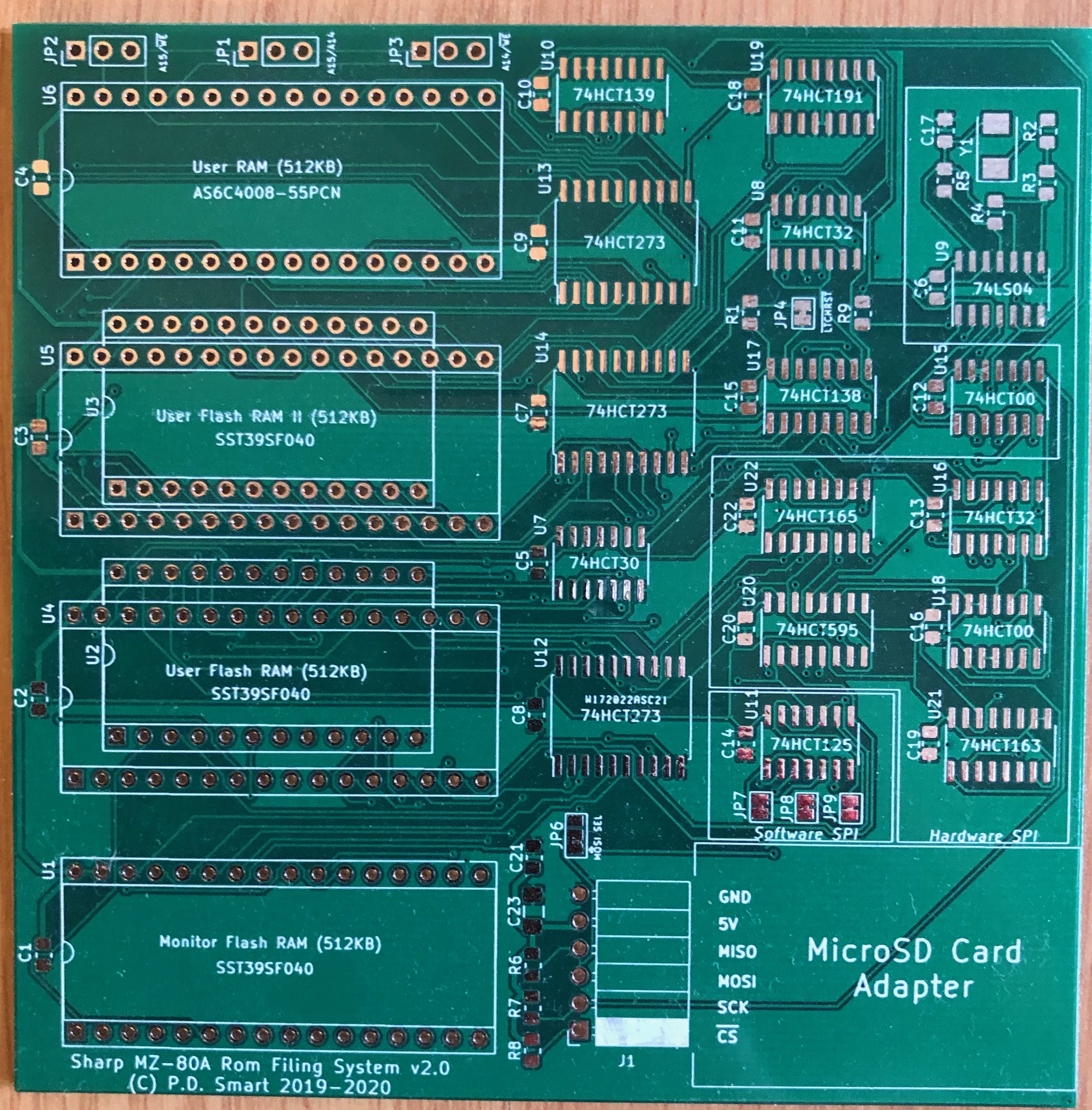
The Sharp MZ-80A RomDisk is a PCB daughter card that plugs directly into the Monitor ROM and User ROM sockets of the Sharp MZ-80A, or the Sharp MZ-1200 if that machine has a User ROM socket fitted. It replaces those two read-only chips with up to four 512KB SST39SF040 Flash RAM devices and one optional 512KB AS6C4008 Static RAM, giving the machine a banked ROM drive of up to 2MB, a hardware SPI interface, and a micro SD card socket for mass storage. The firmware that runs on it — the Rom Filing System (RFS) — provides an enhanced monitor, an SD card filing system holding ten drives of 16MB each, CP/M 2.2 boot, and over thirty new monitor commands, all while keeping the familiar SA-1510
* prompt and every original command intact.
This manual covers the physical hardware: what the RomDisk PCB is, how to install it, how to program its Flash chips, how to prepare an SD card, and how to use the RFS firmware day-to-day. For firmware architecture and build system details see the RFS Technical Guide. For source code internals see the RFS Developer's Guide.
What You Need
Before starting, gather the following items:
| Item | Notes |
|---|---|
| RomDisk PCB | v2.1 recommended (assembled or kit form). v1.1 and v2.0 are also supported with the appropriate firmware build. |
| Sharp MZ-80A or MZ-1200 | The RomDisk physically fits only the MZ-80A or the MZ-1200 (the MZ-1200 requires a User ROM socket to be fitted). The MZ-700 has a similar software architecture but lacks the physical ROM sockets and internal space for the PCB. |
| TL866 II+ or compatible EPROM programmer | Required to write the Flash ROM chips outside the board. The open-source minipro utility is used in the examples below. |
| Micro SD card (≥ 1 GB, FAT-formatted) | The pre-built SD card image is approximately 512MB. Any standard micro SD card of 1GB or larger will work. |
| Pre-built ROM and SD card images | Available in the releases/ directory of the GitHub repository. |
| Anti-static precautions | Anti-static wrist strap or mat. Handle Flash chips and the PCB only after grounding yourself. |
| Chip puller or small flat-blade screwdriver | For removing the existing ROM chips from the motherboard sockets. |
Physical Installation
The RomDisk PCB installs into the Sharp MZ-80A in place of the two factory ROM chips. The procedure below applies to the standard MZ-80A desktop model. Take your time — the process is straightforward but requires care around the chip sockets.
Opening the Machine
- Power off the MZ-80A and disconnect the mains cable.
- Turn the machine upside down. Remove the two screws on the underside of the case.
- Carefully lift the top cover and set it aside. The main PCB is now exposed.
- Locate IC2 (the Monitor ROM, a 24-pin DIP near the centre-left of the board, mapped to 0x0000–0x0FFF) and IC3 (the User ROM, a 24-pin DIP mapped to 0xE800–0xEFFF).
Using a chip puller or a flat-blade screwdriver, carefully lever IC2 and IC3 out of their sockets. Work from both ends in small increments — lever one end up a little, then the other, alternating until the chip slides free. Forcing from one end only will bend the pins. Set both chips aside in a safe, anti-static location; they will not be needed once the RomDisk is installed, but are worth keeping as a fallback.
Seating the RomDisk PCB
- The RomDisk PCB carries two sets of DIP lifter pin arrays on its underside — one 24-pin array for the Monitor ROM socket (IC2) and one 24-pin array for the User ROM socket (IC3). These plug directly into the empty sockets left by the removed ROMs.
- Check the pin 1 orientation before inserting. Pin 1 on each lifter array must align with the pin 1 marker (notch or dot) on the corresponding motherboard socket. Inserting the PCB the wrong way around will prevent the machine from booting and may damage components.
- Press the PCB firmly and evenly into both sockets simultaneously until the pin arrays are fully seated. The PCB will sit raised above the motherboard surface — this is normal.
- Inspect both connectors from the side to confirm all pins have engaged and none are bent or bridging adjacent pins.
- The RomDisk PCB will protrude above the motherboard. Check that no wires, connectors, or components on the underside of the top cover will press against the PCB when the case is reassembled.
The RomDisk v2.0 and v2.1 boards include a micro SD card socket. Because the MZ-80A case is nearly fully enclosed, the socket needs to be accessible from outside or through a gap in the case. Common approaches used by builders include:
Closing the Machine
- Routing the socket cable to the existing tape deck opening on the right side of the machine, where there is already a gap large enough for access.
- Cutting a small slot in the left or rear panel of the case (typically 15 × 2 mm) and hot-gluing the socket flush with the outside surface.
Before closing, do a final visual check: the RomDisk PCB is fully seated in both sockets, pin 1 is aligned on both connectors, and nothing will foul the underside of the top cover. Replace the top cover and refit the two underside screws. Do not overtighten — the plastic standoffs are delicate on older machines.
Programming the Flash ROMs
The Flash ROM chips on the RomDisk PCB must be programmed before the board is installed. The Monitor ROM Flash (U1/SST39SF040 in the Monitor socket) cannot be written in-circuit because the Sharp MZ-80A hardware blocks bus write cycles to the Monitor ROM address space. All chips must be programmed in an external EPROM programmer.
The pre-built ROM images are available in the
releases/ directory of the RFS GitHub repository. Download the following files:
| File | Chip | Socket |
|---|---|---|
MROM_ROMDISK_256.bin |
SST39SF040 | U1 — Monitor ROM Flash (mandatory) |
USER_ROM_256.bin |
SST39SF040 | U4 — User ROM Flash 1 (mandatory) |
USER_ROM_II_256.bin |
SST39SF040 | U5 — User ROM Flash 2 (optional, v2.0+) |
USER_ROM_III_256.bin |
SST39SF040 | U6 — User ROM Flash 3 (optional, v2.0+) |
Use a TL866 II+ or compatible programmer with the
minipro command-line utility. Remove each Flash chip from the RomDisk PCB, insert it into the programmer ZIF socket, and run the appropriate command:
# Program the Monitor ROM Flash (U1):
minipro -p SST39SF040 -w MROM_ROMDISK_256.bin

# Program User ROM Flash 1 (U4):
minipro -p SST39SF040 -w USER_ROM_256.bin

# Program User ROM Flash 2 (U5) — optional:
minipro -p SST39SF040 -w USER_ROM_II_256.bin

# Program User ROM Flash 3 (U6) — optional:
minipro -p SST39SF040 -w USER_ROM_III_256.bin
After programming each chip,
Hardware Version Notes
minipro will automatically verify the written data against the source file. A Verification OK message confirms the chip was written correctly. Re-seat each programmed chip in its socket on the RomDisk PCB.
The Monitor Flash holds eight 4KB banks. The User ROM Flash chips each hold twelve 2KB banks. Together they provide the complete RFS firmware, the ROM drive programs (BASIC, CP/M loader, assembler, etc.), and the banked workspace used during SD card and CP/M operations.
Three versions of the RomDisk PCB exist. The ROM images are compatible across all versions, but the hardware features differ:
| Version | Key Features |
|---|---|
| v1.1 | One 512KB Flash in the Monitor socket, one in the User socket. A simple latch handles bank selection. No SD card. Suitable for ROM-drive use only. |
| v2.0 | Adds a coded latch (74HCT191 counter requiring 16 consecutive reads to addresses 0xEFF8–0xEFFF to unlock control registers), second and third User ROM Flash slots (U5, U6), optional 512KB SRAM (AS6C4008), and an SD card socket with both software bitbang SPI and a dedicated hardware SPI circuit running at 8MHz. |
| v2.1 | Bug fix release. Corrects an interference between the DRAM refresh address decode and the coded latch reset signal by adding an AND gate (built from diodes) and rewiring 0xEFF9 as the latch clear line. All v2.0 features are retained. This is the recommended version for new builds. |
Writing the SD Card Image
The pre-built SD card image bundles ten RFS drives (each 16MB, numbered 0–9) and seven CP/M 2.2 disk images into a single raw binary file. It is written directly to the SD card starting at sector 0 — no partition table is created and no formatting step is required before writing.
Download
SHARP_MZ80A_RFS_CPM_IMAGE_1.img from the releases/ directory of the GitHub repository. Insert the micro SD card into your host computer and identify its device node (e.g. /dev/sdb on Linux). Double-check the device node carefully — writing to the wrong device will overwrite data irreversibly.
# Linux / macOS — replace /dev/sdX with your SD card device node:
dd if=SHARP_MZ80A_RFS_CPM_IMAGE_1.img of=/dev/sdX bs=4M status=progress
sync
The
SD Card Layout
status=progress flag prints a running byte count so you can confirm the write is proceeding. The sync command flushes all pending writes before the card is removed. On macOS, use bs=4m (lowercase) and omit status=progress if your version of dd does not support it.
Once the write completes, eject the card safely from your host computer and insert it into the RomDisk SD card socket.
The image organises storage as follows:
| Region | Offset | Contents |
|---|---|---|
| RFS Drive 0 | 0 MB | Common and MZ-80A machine code programs |
| RFS Drive 1 | 16 MB | MZ-80K machine code programs |
| RFS Drive 2 | 32 MB | MZ-700 machine code programs |
| RFS Drive 3 | 48 MB | MZ-800 / MZ-1500 machine code programs |
| RFS Drive 4 | 64 MB | MZ-80B / MZ-2000 machine code programs |
| RFS Drive 5 | 80 MB | BASIC programs, type 2 (MZ-80A) |
| RFS Drive 6 | 96 MB | BASIC programs, type 2 (MZ-80K) |
| RFS Drive 7 | 112 MB | BASIC programs, type 5 (MZ-700 / MZ-800) |
| RFS Drive 8 | 128 MB | Miscellaneous programs |
| RFS Drive 9 | 144 MB | Miscellaneous programs |
| CP/M disk images | 256 MB | Drives A:–G: (Turbo Pascal, Hi-Soft C, WordStar, Grant Searle collection, etc.) |
First Boot
With the Flash chips programmed and the RomDisk PCB seated in both ROM sockets, power on the MZ-80A. The Monitor ROM detects the RFS firmware at address 0xE800 and executes it. RFS initialises and appends "
+ RFS vx.xx" to the SA-1510 sign-on banner:
SHARP MZ-80A
Monitor SA-1510  + RFS

*
The
* is the monitor prompt. Every original SA-1510 command is available unchanged. Type H and press Enter to display the paginated RFS command help screen. Press Space to advance through pages.
The + RFS line appears whenever RFS itself initialises — it is not dependent on the SD card. After displaying the banner, RFS attempts to initialise the SD card. If the card is absent or fails to initialise, an error code is printed below the banner indicating the failure. The * prompt still appears and all ROM-based commands (IR, LR, etc.) remain available even without a working SD card.
RFS Monitor Commands
The complete set of RFS monitor commands is listed below. All original SA-1510 commands remain available and are not shown here. Addresses and counts are always entered as 4-digit hexadecimal values unless otherwise stated.
| Command | Parameters | Description |
|---|---|---|
| 0 .. 9 | — | Switch the active RFS SD card drive to the given number (0–9). Type the digit and press Enter. |
| 40 | — | Switch to 40-column display mode. Requires a Kuma 40/80 column upgrade or Video Module. |
| 80 | — | Switch to 80-column display mode. Requires a Kuma 40/80 column upgrade or Video Module. |
| B | — | Enable or disable the keyboard entry beep (toggles each time the command is issued). |
| BASIC | — | Locate the BASIC SA-5510 interpreter on the active SD card drive or in ROM, load and execute it. |
| C | [value] |
Clear (initialise) memory from 0x1200 to 0xD000 with 0x00, or with the supplied 8-bit hex value. |
| CP | src dst size |
Copy a block of memory. All three arguments are 4-digit hex: source address, destination address, byte count. |
| CPM | — | Locate CP/M 2.2 on the active SD card drive or in ROM, load and boot it. |
| D | addr [addr2] |
Hex and ASCII dump of memory from addr to addr2 (or 20 lines if no end address given). Press any key to continue, D to page down, U to page up, X to exit. Repeat D without an address to continue from the last position. |
| EC | name or no. |
Erase a file from the active SD card drive, identified by name or by its two-digit hex file number as shown in the IC directory. |
| F | [drive] |
Boot from floppy disk. If no drive number is supplied you are prompted to enter one. |
| f | — | Execute the original floppy AFI boot ROM code at address 0xF000 directly. |
| H | — | Display the paginated command help screen. Press Space to advance through pages. |
| IC | — | Paged directory listing of files on the active SD card drive. Shows file number and filename. Press Space to page, X to exit. |
| IR | — | Paged directory listing of programs stored in the Flash ROM drives. These are read-only and always available. |
| J | address |
Jump to (execute from) the given hex address. |
| L / LT | [filename] |
Load a file from tape (CMT) and execute it. If a filename is given, the tape is searched for that name; otherwise the next file is loaded. |
| LTNX | [filename] |
Load a file from tape (CMT) without executing. |
| LR | name or no. |
Load a program from the Flash ROM drive by name or file number and execute it. |
| LRNX | name or no. |
Load a program from the Flash ROM drive by name or file number without executing. |
| LC | name or no. |
Load a program from the active SD card drive by name or file number and execute it. |
| LCNX | name or no. |
Load a program from the active SD card drive by name or file number without executing. |
| M | address |
Interactive memory editor. Displays the current byte value at the given address; type a new hex value and press Enter to change it, or press Enter alone to leave it unchanged and advance to the next address. Press X to exit. |
| P | — | Run a test on the connected printer. |
| R | — | Run a comprehensive DRAM memory test over the range 0x1200–0xCFFF. |
| S / ST | start end exec |
Save a memory range to tape (CMT). All three arguments are 4-digit hex run together without spaces (e.g. S120020001200). You are then prompted for a filename. |
| SC | start end exec |
Save a memory range to the active SD card drive. Arguments are as for S. You are prompted for a filename. |
| SD2T | name or no. |
Copy a file from the active SD card drive to tape (CMT). Press Record on the tape deck when prompted. |
| T | — | Test the 8253 timer chip. |
| T2SD | — | Load a program from tape (CMT) and write it to the active SD card drive. Press Play on the tape deck when prompted. |
| V | — | Verify a file just saved to tape against the data currently in memory. |
| X | — | Exchange to the hi-load ROM variant, changing the DRAM mapping so it spans 0x0000–0xCFFF. |
Using SD Card Drives
RFS provides ten logical SD card drives numbered 0 through 9. Each drive occupies a 16MB region of the SD card and holds a flat directory of up to 256 files, each stored in Sharp MZF format. Files can be up to 64KB in size.
Type the drive number (0–9) at the monitor prompt and press Enter to make that drive active. The IC and IR commands always operate on the currently active drive.
Listing Files
Type IC to display the directory of the active SD card drive. Each entry shows a two-digit hex file number followed by the filename. In 80-column mode, four columns are displayed simultaneously.
* IC

00 INVADERS     01 DEFENDER     02 GALAXIANS    03 SPACE ATTACK
04 PACMAN       05 SNAKE        06 FROGGER      07 BREAKOUT
...
Press SPACE to continue, X to exit
Type IR to list programs stored in the Flash ROM drives. These are read-only and are available regardless of whether an SD card is inserted.
Loading Programs
Programs can be loaded by name or by the two-digit hex file number shown in the IC directory. Loading by number is slightly faster as no name search is required:
* LC INVADERS       ; Load and execute INVADERS from the active SD drive
* LCNX INVADERS     ; Load without executing
* LC 04             ; Load and execute file number 04
* LR SA-5510RFS     ; Load and execute SA-5510RFS from the ROM drive
Saving Programs
Use SC to save a region of memory to the active SD card drive. The syntax matches the tape S command — start address, end address, and execution address as 4-digit hex values concatenated without spaces, after which you are prompted for a filename:
* SC120020001200
FILE NAME? MYPROG
SAVED
Erasing Files
Use EC followed by a filename or file number to erase a file from the active SD card drive. The operation cannot be undone, so confirm the file number with IC before erasing.
* EC MYPROG     ; Erase by name
* EC 04         ; Erase by file number
Display Modes
If a Kuma 40/80 column upgrade or the 40/80 colour Video Module is fitted to the MZ-80A, RFS can switch between 40-column and 80-column display modes at the monitor prompt:
* 40    ; Switch to 40-column display
* 80    ; Switch to 80-column display
In 80-column mode the IC and IR directory commands display four columns of filenames simultaneously, making it much faster to scan a full drive directory. The BASIC SA-5510RFS and Microsoft BASIC variants each have separate ROM builds for 40-column and 80-column use — load the appropriate variant for your display configuration.
Without the 40/80 upgrade fitted, the
40 and 80 commands are still accepted but have no visible effect. All other RFS commands operate normally in standard 40-column mode.
Tape Operations
RFS retains all original SA-1510 tape (CMT) commands and adds two new commands for transferring files between tape and the SD card.
Loading and Saving to Tape
The standard tape commands work exactly as in the original SA-1510 monitor:
Tape to SD Card Transfer
- L or LT — load the next file from tape and execute it. Optionally supply a filename to search for a specific program.
- LTNX — as above but load without executing.
- S or ST — save a memory range to tape. Supply start, end, and execution addresses as 4-digit hex concatenated (e.g.
S120020001200), then enter a filename when prompted. - V — verify the last tape save against memory.
T2SD reads the next program from tape and writes it directly to the active SD card drive. This is the most convenient way to archive an existing tape library to the SD card:
* T2SD
PRESS PLAY
...
Press Play on the tape deck when prompted. RFS will load the program into memory and then write it to the SD card under its original tape filename. The program is not executed.
SD Card to Tape Transfer
SD2T reads a file from the active SD card drive and writes it to tape, reproducing the original tape framing exactly. This is useful for distributing software or creating backup tapes from the SD card collection:
* SD2T INVADERS
PRESS REC
...
Press Record on the tape deck when prompted. The file is written to tape at the standard SA-1510 baud rate.
Using BASIC SA-5510
Type BASIC at the monitor prompt to load and launch the Sharp SA-5510 BASIC interpreter. RFS searches the active SD card drive first, then the ROM drive, for the SA-5510RFS build. This extended version of the original SA-5510 interpreter adds
LOAD, SAVE, and DIR commands that work with the RFS SD card filing system, while preserving full compatibility with all original SA-5510 BASIC programs and cassette commands.
* BASIC

SHARP MZ-80A BASIC SA-5510RFS

READY
The RFS-extended BASIC commands are:
| Command | Example | Description |
|---|---|---|
| LOAD | LOAD "TEST" |
Load and run the BASIC program named TEST from the active SD drive. |
| LOAD | LOAD "3:TEST" |
Load TEST from SD drive 3 (drive 3 becomes active). |
| LOAD | LOAD "C:TEST" |
Load TEST from tape (CMT). |
| LOAD | LOAD |
Load the next sequential file from the active drive. |
| SAVE | SAVE "TEST" |
Save the current BASIC program to the active SD drive. Overwrites an existing file of the same name. |
| SAVE | SAVE "3:TEST" |
Save to SD drive 3 (drive 3 becomes active). |
| SAVE | SAVE "C:TEST" |
Save to tape (CMT). |
| DIR | DIR |
List the SD card directory for the active drive. |
| DIR | DIR "3:" |
List SD drive 3 and make it active. |
All original SA-5510 cassette BASIC commands (
CLOAD, CSAVE, etc.) continue to work unchanged when no drive qualifier is given.
Running CP/M 2.2
Type CPM at the monitor prompt to boot CP/M 2.2. RFS locates the CP/M boot sector on the active SD card drive, loads the CCP and CBIOS, and transfers control. The prompt changes to
A>.
* CPM

CP/M 2.2 - SHARP MZ-80A

A>
The CBIOS implementation lives entirely in Flash ROM, leaving the full 47KB TPA free for application programs. Up to seven CP/M drives are provided:
| CP/M Drive | Contents |
|---|---|
| A: | SD card — CP/M system programs, Turbo Pascal, Hi-Soft C, etc. |
| B: | SD card — Pascal utilities and Pascal User Group disks |
| C: | SD card — PLI, PLM, WordStar |
| D:–G: | SD card — Grant Searle CP/M collection |
The built-in ANSI terminal emulator maps standard ANSI escape sequences to the MZ-80A screen, so most CP/M applications that use screen control work correctly without modification. The MZ-80A keyboard is fully mapped, including auto-repeat.
To return to the RFS monitor from CP/M, perform a warm boot with Ctrl+C from the CCP prompt, which reloads the CCP. A full return to the SA-1510 monitor requires a hardware reset (the Reset button, or power cycle).
Troubleshooting
No "+ RFS" text after the sign-on banner
The
+ RFS line is output by the RFS firmware itself immediately on initialisation — it appears whether or not an SD card is present. If it is missing entirely, the RFS ROM is not being executed:
- Flash ROMs not programmed or programmed incorrectly — the machine may be running the original Monitor ROM or an uninitialised chip. Confirm that
MROM_ROMDISK_256.binwas written to the Monitor Flash chip (U1) and thatUSER_ROM_256.binwas written to U4. Useminipro's verify step to confirm each chip. - PCB not fully seated — remove the top cover and press both DIP lifter arrays firmly into their sockets. Inspect from the side to confirm all pins have engaged and none are bent or bridging adjacent pins.
- Coded latch triggered by refresh cycles (v2.0 only) — on v2.0 boards the DRAM refresh logic can inadvertently increment the 74HCT191 counter before RFS runs, causing the bank select registers to activate prematurely. The v2.1 board adds an AND gate (D1/D2) to prevent this. If using a v2.0 board, consider upgrading to v2.1.
SD card error code after the "+ RFS" line
If
+ RFS appears but is followed by an error code, RFS initialised successfully but the SD card could not be detected or initialised. The error number indicates the point of failure in the SD card initialisation sequence. Check the following:
- SD card not inserted — check the card is fully seated in the socket.
- SD card socket cable — if the cable was routed through a slot in the case, check it is not kinked or partially disconnected.
- SD card image not written — an unformatted or empty card will fail initialisation. Re-write using the
ddcommand as described above. Ensure the full image was transferred (syncafter the write). - Incompatible SD card — older or very high-capacity (≥ 32GB, SDXC class) cards may not initialise correctly. A standard 2GB–8GB SD or SDHC card is most reliable.
Machine does not boot at all — blank screen or garbage
- PCB inserted the wrong way around — check the pin 1 alignment on both DIP lifter arrays. A reversed connector will prevent the machine from booting. Power off immediately if this is suspected, and re-seat with correct orientation.
- Bent or missed pins — remove the PCB and inspect all pins on both lifter arrays under good lighting. Straighten any bent pins before re-seating.
- Wrong ROM image for hardware — verify that the Monitor Flash was programmed with
MROM_ROMDISK_256.bin(not a picoZ80 or SFD-700 image).
IC shows an empty directory or "SD ERROR"
- SD card written incorrectly — the image must be written as a raw binary to sector 0 with no partition table. Formatting the SD card as FAT first and then copying the image file onto it will not work. Re-write with
ddas described in the Writing the SD Card Image section. - SD card not seated — the micro SD card socket uses a push-push mechanism on v2.x boards. Push the card in firmly until it clicks. To eject, push in again until it clicks and release.
- Incompatible SD card — older or very high-capacity (≥ 32GB, SDXC class) cards may not initialise correctly. A standard 2GB–8GB SD or SDHC card is most reliable.
CP/M does not boot or shows disk errors
- Wrong active drive — select drive 0 before typing CPM. The pre-built image places the CP/M boot sector on drive 0. Type
0and press Enter at the monitor prompt, then typeCPM. - SD card image incomplete — the CP/M disk images begin at the 256MB boundary. A partial
ddwrite (interrupted or with an undersized SD card) will leave the CP/M area uninitialised. Re-write with a card of at least 512MB.
Tape load or save fails or produces errors
- Tape timing on the MZ-80A is sensitive to CMT head alignment and tape quality. If loads fail consistently, use the TC command to adjust the tape read delay compensation:
TC01increases the delay by one step,TC-01decreases it. Start with a single step in each direction and test after each adjustment. - Ensure the tape volume is set appropriately on the CMT deck — too high causes clipping, too low causes missed pulses.
Reference Sites
| Resource | Link |
|---|---|
| RomDisk project page | /sharpmz-upgrades-romdisk/ |
| RFS User Manual | /sharpmz-upgrades-rfs-usermanual/ |
| RFS Technical Guide | /sharpmz-upgrades-rfs-technicalguide/ |
| RFS Developer’s Guide | /sharpmz-upgrades-rfs-developersguide/ |
| RFS Gallery | /sharpmz-upgrades-rfs-gallery/ |
| picoZ80 (RP2350 Z80 replacement) | /picoz80/ |
| tranZPUter FusionX | /transzputer-fusionx/ |
| minipro (open-source TL866 utility) | https://gitlab.com/DavidGriffith/minipro |