 SFD-700 mkII User Manual
SFD-700 mkII User Manual
The SFD-700 mkII is a floppy disk interface card for the Sharp MZ series of home and business computers. It allows you to connect standard 3.5″ or 5.25″ floppy disk drives to machines that were never designed with built-in floppy support — or that required a proprietary and now hard-to-find expansion card. Unlike the original 1985 Kersten & Partners SFD-700 which only worked in the MZ-700 (and only inside the MZ-1U06 expansion unit), the mkII is a completely new design that supports seven different Sharp MZ host machines from a single board by means of a three-bit MODE jumper.
This manual covers everything needed to build, install, and use the SFD-700 mkII in your Sharp MZ computer. For in-depth hardware and logic details see the Technical Guide. For information on modifying the CPLD logic or ROM firmware see the Developer's Guide.
What You Need
Hardware
- An SFD-700 mkII v1.2 PCB — six spare boards are available from the author (postage cost only); contact via the website. Gerber files are in the
releases/directory of the repository for self-manufacture. - All components listed in the Bill of Materials (the KiCAD interactive BOM is included in
kicad/v1.0/bom/ibom.html). - An Altera USB-Blaster (or clone) JTAG programmer for programming the CPLD after assembly.
- One or two 3.5″ PC-compatible floppy disk drives (DD or HD). 5.25″ drives are also supported.
- A 34-pin IDC floppy ribbon cable. If using two drives, the cable must have three connectors (PC-style with twist between drive B and A connectors).
- A floppy power cable splitter (4-pin Molex or Berg/mini connector depending on your drive type).
- An expansion connector for your specific host machine — see Host Connectors below.
- Quartus II 13.0.1 SP1 Web Edition — required to compile the CPLD VHDL source. This specific version is needed because later releases dropped MAX7000S device support. Available from the Intel FPGA Software Archive.
- Logical Devices CUPL v4.0 (optional, for v1.0/v1.1 GAL files only) — can be run under DOSBox.
- Soldering iron with fine tip, solder, and flux.
- PLCC-84 socket (required — the EPM7128SLC84 is a surface-mount PLCC device and should be fitted in a socket for reprogramming).
- Static-safe mat and wrist strap — CMOS devices are static-sensitive.
Board Overview
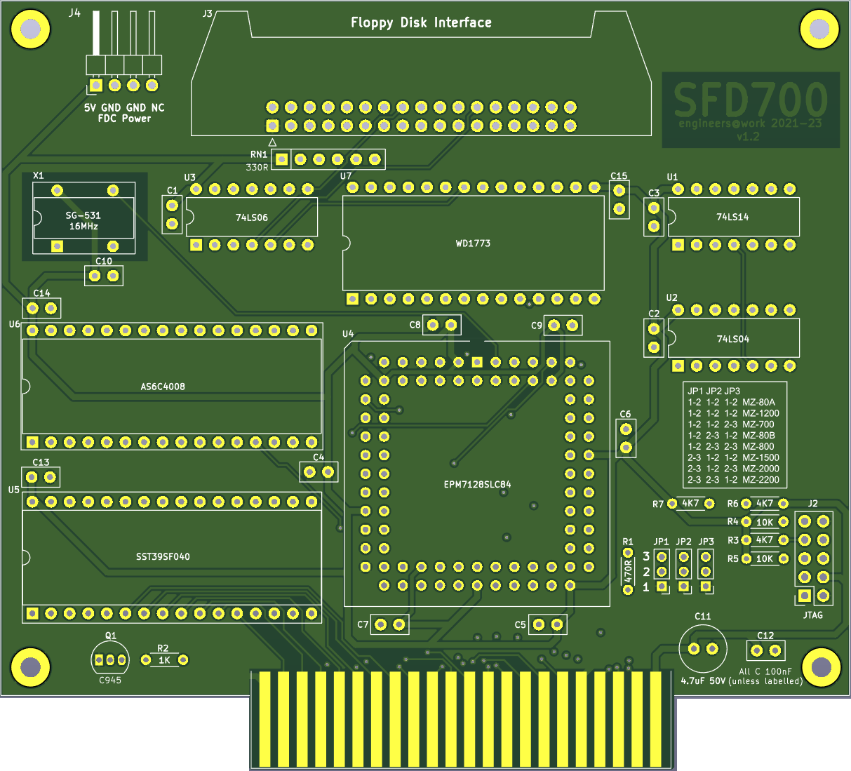
The SFD-700 mkII v1.2 PCB carries the following key components. Understanding their locations before assembly will make the build process straightforward.
| Reference | Component | Description |
|---|---|---|
| U1 | EPM7128SLC84-15 | Altera MAX7000S CPLD in 84-pin PLCC package — implements all bus logic |
| U2 | WD1773 | Western Digital Floppy Disk Controller IC |
| U3 | SST39SF040 (or compatible) | 512 KB Flash ROM — stores boot firmware (AFI ROM, ROM Filing System pages) |
| U4 | 62256 (32KB SRAM) | Static RAM for ROM Filing System workspace |
| X1 | 16 MHz crystal oscillator | Primary clock source — divided to 8 MHz for the WD1773 |
| J1 | MODE jumper (3-pin × 1) | Selects the host machine (see MODE Jumper) |
| J2 | JTAG header (10-pin) | Used for CPLD programming via USB-Blaster |
| J3 | Floppy connector (34-pin IDC) | Connects to floppy drives via standard ribbon cable |
| J4 | Host bus connector | Connects to the Sharp MZ expansion bus |
v1.2 PCB

Setting the MODE Jumper
The three-bit MODE jumper (J1) tells the CPLD which Sharp MZ host machine the card is installed in. The value is latched by the CPLD on every system reset — it is read once at power-on and stored internally. You must set the jumper before powering on the host computer. Changing the jumper while powered will have no effect until the next reset.
The jumper is a 3-position binary header. Shorting a jumper position contributes 1 to the MODE value; leaving it open contributes 0. The full truth table is:
| MODE | Binary (bit2:bit1:bit0) | Host Machine |
|---|---|---|
| 0 | 0 : 0 : 0 | Sharp MZ-80A / MZ-1200 |
| 1 | 0 : 0 : 1 | Sharp MZ-700 |
| 2 | 0 : 1 : 0 | Sharp MZ-80B |
| 3 | 0 : 1 : 1 | Sharp MZ-800 |
| 4 | 1 : 0 : 0 | Sharp MZ-1500 |
| 5 | 1 : 0 : 1 | Sharp MZ-2000 |
| 6 | 1 : 1 : 0 | Sharp MZ-2200 |
MZ-80A / MZ-1200 (MODE 0)
The MZ-80A runs its Z80 CPU at 2 MHz, which is too slow to reliably poll the WD1773's DRQ (Data Request) flag and fetch each byte before the next one arrives. The CPLD handles this automatically in MODE 0 by routing the DRQ signal directly to Flash ROM address bit A10. Duplicate copies of the read routine are stored in each 1 KB segment of the boot ROM — the DRQ state selects the correct path directly in hardware, bypassing the software polling loop entirely. You do not need to configure anything for this; it is automatic. MZ-700 / MZ-1500 (MODEs 1 and 4)
These machines have a memory management controller that can bank their internal DRAM and CGROM in and out of the upper address space (D000h–FFFFh). The CPLD monitors the memory management I/O ports (0xE0–0xE6) and automatically enables or disables the SFD-700's onboard Flash ROM and RAM in response to keep everything consistent with the host's paging state. MZ-80B, MZ-800, MZ-2000, MZ-2200 (MODEs 2, 3, 5, 6)
These machines include floppy disk bootstrap firmware in their built-in IPL ROMs, so the SFD-700's onboard Flash ROM is not mapped into the address space. The CPLD still handles I/O decoding, FDC control, and the data bus inversion required by the WD1773. The machine's own IPL code talks directly to the WD1773 through the CPLD's I/O port decode logic.
Host Connectors
Each Sharp MZ machine provides its expansion bus through a different connector. Below is a summary of the connection method for each supported host.
| Host | Expansion Method | Notes |
|---|---|---|
| MZ-80A / MZ-1200 | Direct edge connector on rear expansion port | 50-pin or 60-pin bus connector depending on revision |
| MZ-700 | MZ-1U06 expansion unit or custom adapter | See note below regarding MZ-1U06 vs. custom adapter |
| MZ-80B | Rear expansion slot | Standard MZ-80B bus header |
| MZ-800 | Rear expansion slot | MZ-800 bus connector |
| MZ-1500 | EXT700 adapter or direct rear expansion | The EXT700 adapter (separate project) interfaces the MZ-700-style expansion bus |
| MZ-2000 | MZ-2000 expansion unit | Slot in the expansion chassis |
| MZ-2200 | MZ-2200 expansion slot | Rear expansion connector |
MZ-700 note: The original K&P SFD-700 was designed exclusively for use inside the MZ-1U06 expansion unit, which provided external paging logic. The SFD-700 mkII contains its own paging logic in the CPLD and works both inside the MZ-1U06 and in any custom expansion adapter — this is one of the key improvements over the K&P original.
Installing in the Host Computer
Safety first: Always power off the host computer and unplug it from the mains before installing or removing any expansion card. The Sharp MZ machines run at 5V; inserting or removing cards while powered can damage both the card and the host.
General installation procedure:
- Set the MODE jumper (J1) on the SFD-700 mkII for your host machine before installing the card.
- Power off and unplug the host computer.
- Insert the SFD-700 mkII into the appropriate expansion slot or adapter for your machine. Ensure all edge connector pins are making solid contact.
- Connect the 34-pin floppy ribbon cable from J3 on the SFD-700 mkII to your floppy drive(s). See Connecting Floppy Drives below.
- Connect floppy drive power from the host's internal power supply or an external supply.
- Power on the host computer.
Connecting Floppy Drives
The SFD-700 mkII supports up to four drives (A through D). In practice, one or two drives is the most common configuration. Standard 3.5″ PC-compatible double-density (DD) or high-density (HD) drives work, as does 5.25″ equipment.
Drive Select and Motor Control
Drive selection is controlled by writing to I/O port 0xDC. The lower three bits encode the active drive:
| Bits [2:0] value | Drive Selected |
|---|---|
| 0 | None (deselect all) |
| 4 | Drive A |
| 5 | Drive B |
| 6 | Drive C |
| 7 | Drive D |
Bit 7 of the same byte controls the spindle motor — write 1 to start the motor, 0 to stop it. The motor must be running (and the drive head settled) before issuing read or write commands to the WD1773.
Cable note: Standard PC floppy cables have a twist between the B and A connectors. If using a twist cable, the drive physically connected to the end connector (after the twist) responds as Drive A; the middle connector is Drive B. Both drives should have their DS (Drive Select) jumper set to DS1 (Drive 1) when using a twist cable. If using a straight (no-twist) cable, set the drive select jumpers individually (DS0 for Drive A, DS1 for Drive B).
Termination: Only the last drive on the cable should have its termination resistor pack fitted. On most modern 3.5″ drives the terminator is built in and cannot be removed — this is fine for single-drive configurations. For two-drive configurations with older 5.25″ drives, remove the terminator from Drive A (the middle connector) and leave it fitted only on Drive B (end of cable).
Power-On and Initial Testing
After installation and drive connection, power on the host computer. The expected behaviour depends on the host machine:
MZ-80A / MZ-1200: The machine will boot normally from its built-in Monitor ROM. To boot from a floppy disk, type F at the Monitor prompt. The SFD-700 mkII's AFI ROM will take control, spin up Drive A, and attempt to load the boot sector.
MZ-700: Similarly, boot normally and type F at the Monitor prompt to initiate a floppy boot. If the ROM Filing System (RFS) has been programmed into the SFD-700 mkII's Flash ROM, the sign-on banner will include "
+ RFS" and the full RFS command set will be available at the * prompt — see the ROM Filing System section below.
MZ-80B, MZ-800, MZ-2000, MZ-2200: These machines will auto-boot from floppy if a bootable disk is inserted in Drive A and the machine's IPL detects the drive. On the MZ-80B and MZ-800, the built-in Monitor firmware directly initialises the WD1773 via the SFD-700's I/O ports.
MZ-1500: Requires the EXT700 adapter or equivalent. Follow the MZ-700 boot procedure once the adapter is connected.
If the machine does not respond to floppy commands, check the MODE jumper setting, verify the ribbon cable orientation (pin 1 of the cable, usually indicated by a red stripe, must align with pin 1 of J3 on the SFD-700 mkII), and ensure the drive has power.
ROM Filing System (RFS)
The ROM Filing System (RFS) is a suite of software stored in the SFD-700 mkII's Flash ROM that extends the host machine's Monitor with a comprehensive set of enhanced commands. RFS is ported from the tranZPUter project and adapted for the SFD-700 mkII hardware. On boot, the familiar SA-1510 Monitor sign-on banner is appended with "
Flash ROM Page Layout
+ RFS" when the filing system has initialised successfully, and the standard * prompt appears. All original SA-1510 commands remain available alongside the RFS extensions listed below.
The 512 KB Flash ROM is divided into 4 KB pages. The CPLD provides two independently paged 4 KB windows:
Available Commands
- FXXX window (F000h–FFFFh): Page 0 holds the MZ-80A AFI boot ROM. Page 1 holds the MZ-700 AFI boot ROM. Higher pages hold RFS modules. The active page is selected by writing to I/O port 0x61.
- EXXX window (E300h–EFFFh): Pages here hold additional RFS code and data. The active page is selected by writing to I/O port 0x60. Only 3.75 KB of each 4 KB page is usable (E000h–E2FFh is reserved for MZ-700/MZ-1500 memory-mapped I/O).
The full set of RFS monitor commands available on the SFD-700 mkII are listed below.
| Command | Parameters | Description |
|---|---|---|
| ASM | <address> | Invoke the built-in Z80 assembler starting at <address>. Enter mnemonics line by line; assembled bytes are written directly to RAM and the address advances automatically. |
| B | n/a | Enable/Disable key entry beep. |
| BASIC | n/a | Locate BASIC SA-5510 in ROM, load and execute it. |
| C | [<8 bit value>] | Initialise memory from 0x1200 to top of RAM with 0x00 or the supplied byte value. |
| CP | <src addr> <dst addr> <size> | Copy a block of memory. All three arguments are 4-digit hex: source address, destination address, byte count. Eg. CP120020003FFF copies 0x3FFF bytes from 0x1200 to 0x2000. |
| CPM | n/a | Locate CP/M 2.2 in ROM, load and boot it. |
| D | <address>[<address2>] | Dump memory from <address> to <address2> (or 20 lines) in hex and ASCII. Output pauses at each screenful; press a key to continue, ‘U’ to page up, ‘X’ to exit. Repeating ‘D’ without an address continues from the last displayed location. |
| DASM | <address>[<address2>] | Invoke the built-in Z80 disassembler from <address> to <address2>. Displays address, hex bytes and mnemonic for each instruction. |
| F | n/a | Boot from the SFD-700 floppy disk. Verifies the AFI boot ROM is present at 0xF000 and transfers control to it. |
| H | n/a | Display the paginated help screen of all available commands. |
| IR | n/a | Paged directory listing of programs stored in the Flash ROM drives. Each entry shows a hex file number and filename. |
| J | <address> | Jump to (start execution at) the given address. |
| L | LT | [<filename>] | Load a file from tape (CMT) and execute it. |
| LTNX | [<filename>] | Load a file from tape (CMT) without executing. |
| LR | <name> or <file no.> | Load a program from ROM by name or file number and execute it. |
| LRNX | <name> or <file no.> | Load a program from ROM by name or file number without executing. |
| M | <address> | Interactive memory editor starting at <address>. Shows the current byte value; type a new hex value and press Enter to write it, or press Enter alone to leave it unchanged. |
| P | n/a | Run a test on the connected printer. |
| R | n/a | Run a comprehensive DRAM memory test across 0x1200–0xCFFF. Reports any failed addresses. |
| S | ST | <start addr> <end addr> <exec addr> | Save a block of memory to tape (CMT). You will be prompted for a filename. Eg. S120020001203 saves from 0x1200 to 0x2000 with execution address 0x1203. |
| T | n/a | Test the 8253 timer. |
| V | n/a | Verify a file just saved to tape against the original data in memory. |
Troubleshooting
Host computer does not respond to floppy commands
- Check MODE jumper — verify J1 is set correctly for your host machine. An incorrect MODE will cause the CPLD to decode the wrong I/O address range or fail to map the boot ROM.
- Check card seating — remove and reinsert the SFD-700 mkII, ensuring all edge connector pins make firm contact.
- Check CPLD programming — if the CPLD has not been programmed (e.g. fresh from the manufacturer), the card will not function. Program the CPLD using the Quartus Programmer or a USB-Blaster via the JTAG header J2. See the Technical Guide — Programming the CPLD.
- Verify the Flash ROM is programmed — the Flash ROM must contain the AFI boot code for your machine. Program using a standard EPROM/Flash programmer with the appropriate binary from the
ROM/directory of the repository.
Drive does not spin up or seek
- Check power — ensure the floppy drive is receiving 5V and 12V (for 5.25″ drives). 3.5″ drives typically require only 5V.
- Check ribbon cable orientation — the red stripe on the ribbon cable (pin 1) must align with pin 1 of J3 on the SFD-700 mkII and with pin 1 of the drive's connector.
- Check the drive select write — the firmware must write the correct value to port 0xDC with the motor bit (bit 7) set to 1, followed by a wait for the motor to spin up before issuing any WD1773 commands.
- Check termination — incorrect termination can cause signal reflection that prevents the drive from responding. Only the last drive on the cable should be terminated.
Read errors / CRC errors on floppy
- Check disk density setting — write the correct value to port 0xDE. Bit 0 low = double density (MFM), bit 0 high = single density (FM). Most modern 3.5″ drives and CP/M disks use double density.
- Check disk format — the WD1773 is a standard MFM/FM controller. Disks formatted on incompatible geometry (wrong track count, sector size, or interleave) will produce errors. Use the RFS format tool to prepare disks specifically for the SFD-700 mkII.
- Try a different disk — floppy media degrades over time. Persistent read errors on multiple disks may indicate a dirty or misaligned drive head; clean with a head-cleaning disk.
- MZ-80A data rate issue — if running in MODE 0 (MZ-80A) and seeing intermittent errors, confirm the CPLD is programmed with the latest bitstream. The DRQ-to-ROM-A10 routing that handles the 2 MHz CPU speed limitation must be working correctly.
MZ-700: ROM not visible after certain software operations
- This is expected behaviour. When MZ-700 software writes to I/O port 0xE1 (map DRAM to D000h–FFFFh) or 0xE5 (inhibit all upper memory), the CPLD correctly disables the SFD-700 mkII's ROM and RAM. Writing 0xE3, 0xE4, or 0xE6 re-enables them. This is how the MZ-700 memory management system works and the CPLD tracks it transparently.
- If the ROM disappears permanently and cannot be recovered, check that the CPLD is receiving the Z80_RESETn signal correctly — a reset clears both paging state bits and restores the default ROM mapping.
Reference Sites
| Resource | Link |
|---|---|
| SFD-700 mkII project page | /sfd700/ |
| SFD-700 mkII Technical Guide | /sfd700-technicalguide/ |
| SFD-700 mkII Developer’s Guide | /sfd700-developersguide/ |
| SFD-800 (companion MZ-800 card) | /sfd800/ |
| K&P SFD-800 Manual (German) | /Downloads/Manuals/KandP/sfd_mfd800.pdf |
| WD1773 Datasheet | Western Digital / BPCD archives |
| Altera MAX7000S Datasheet | Intel FPGA product page |
| Quartus II 13.0.1 SP1 Web Edition | Intel FPGA Software Archive |