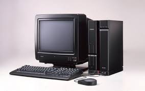
 Sharp X68000 Renovation Expert (Grey)
Summary
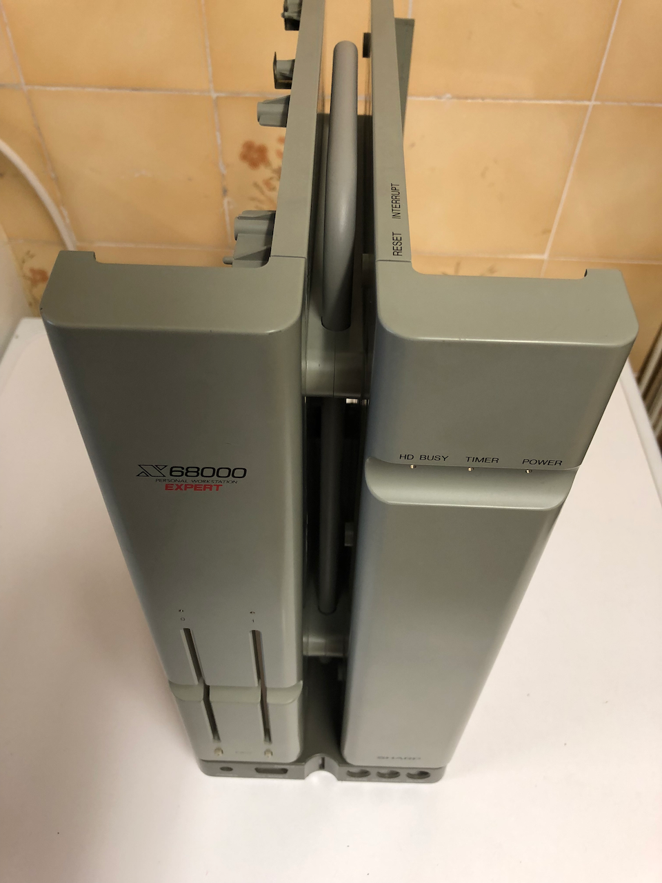
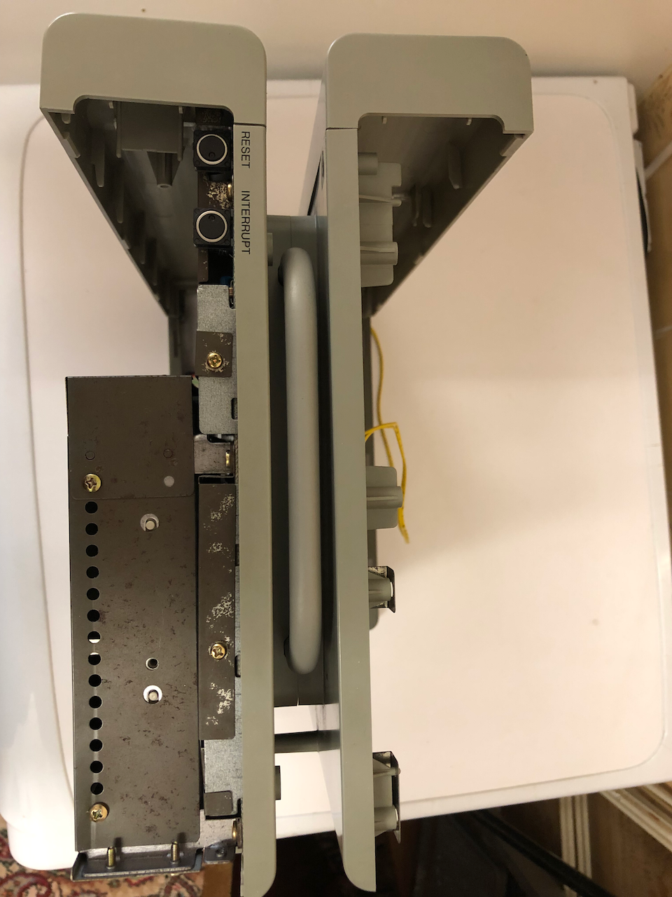
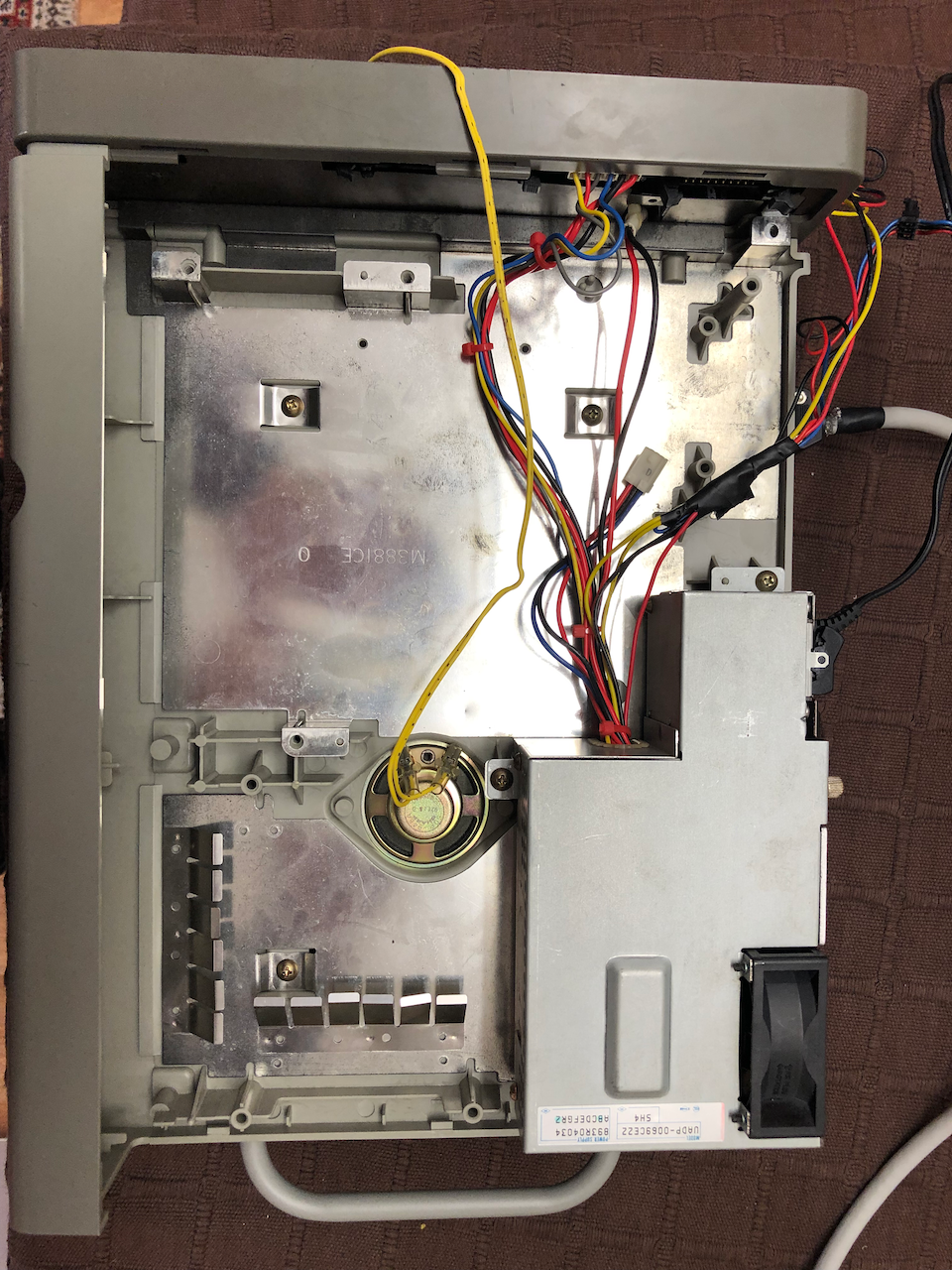
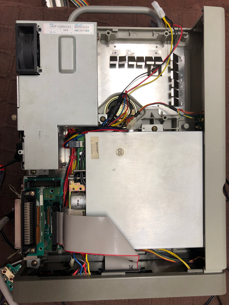
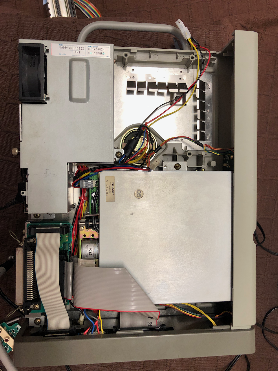
Strip Down
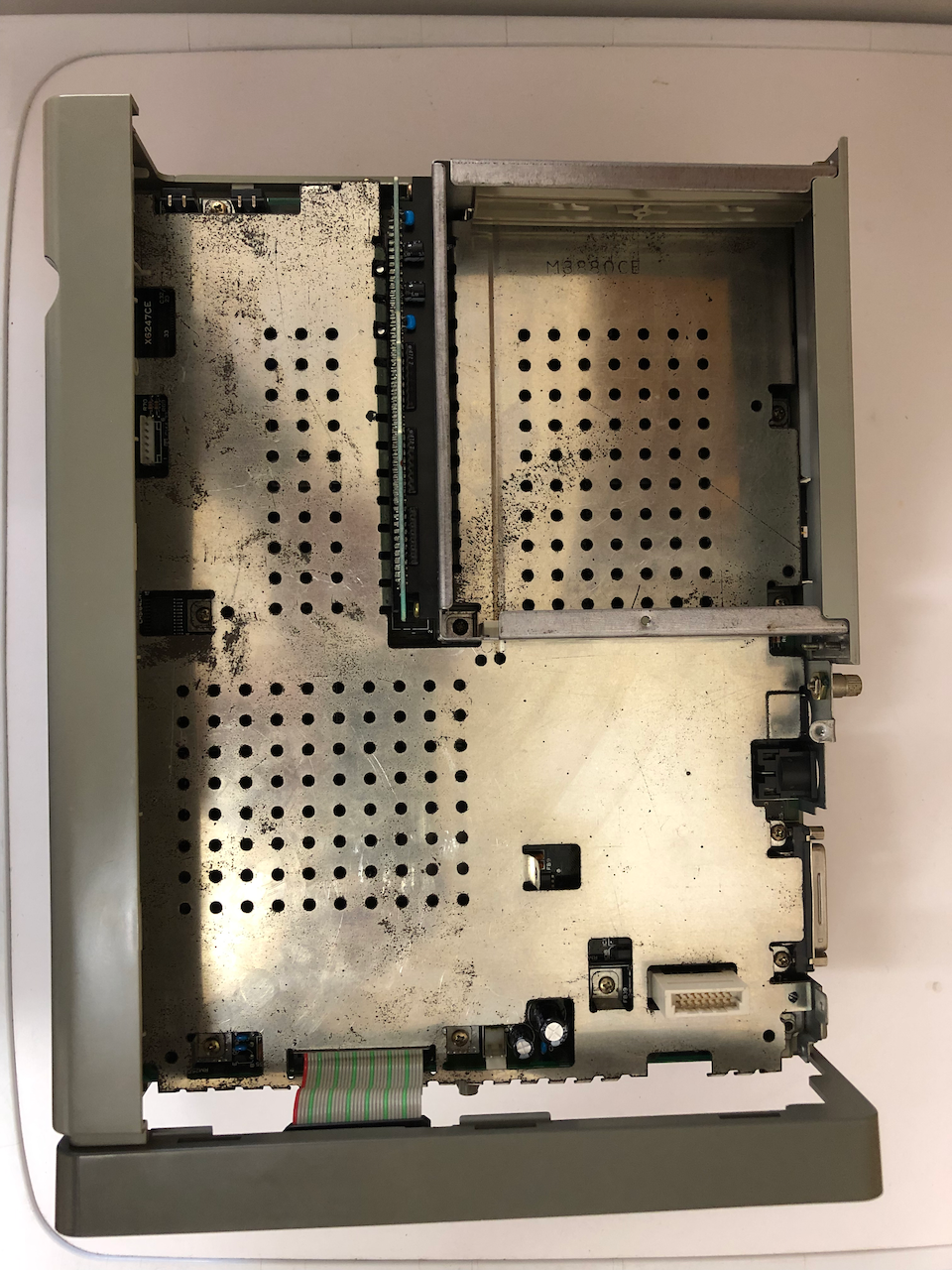
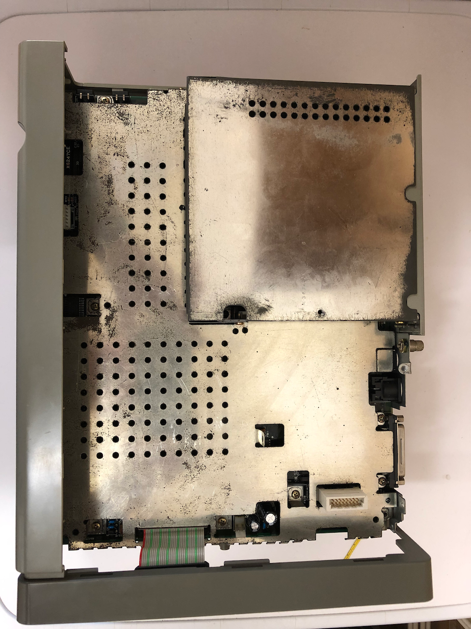
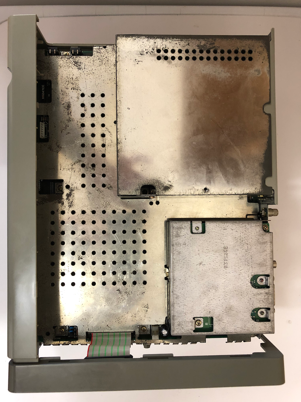
Side panels removed, there was a lot of rusting on the chrome shielding, I had come to expect this after working on previous MZ machines.
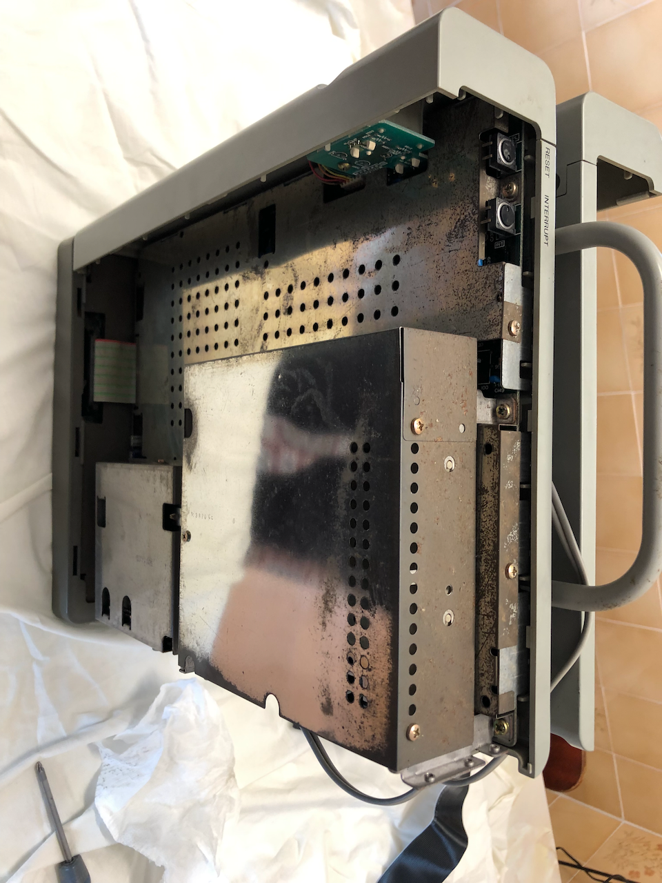
Compare and contrast with the X68000 HD, the HD was in much better condition.
The plastics were soaked in warm soap suds as the usual black oily film was present, a gift from the passage of time (and pollution)!.
Carbon and rust are real enemies of electronics yet people allow them to build up, probably unaware. Washing the circuit boards in clean Isopropyl alcohol there is a considerable deposit of dirt and carbon removed as is evident in the wash. If I see any IC's with oxidization I apply contact cleaner, doing this for all connectors as well, both socket and plug, all variable resistors etc. It is important to re-grease any moving part which previously used grease (often white powdery deposit) after cleaning.
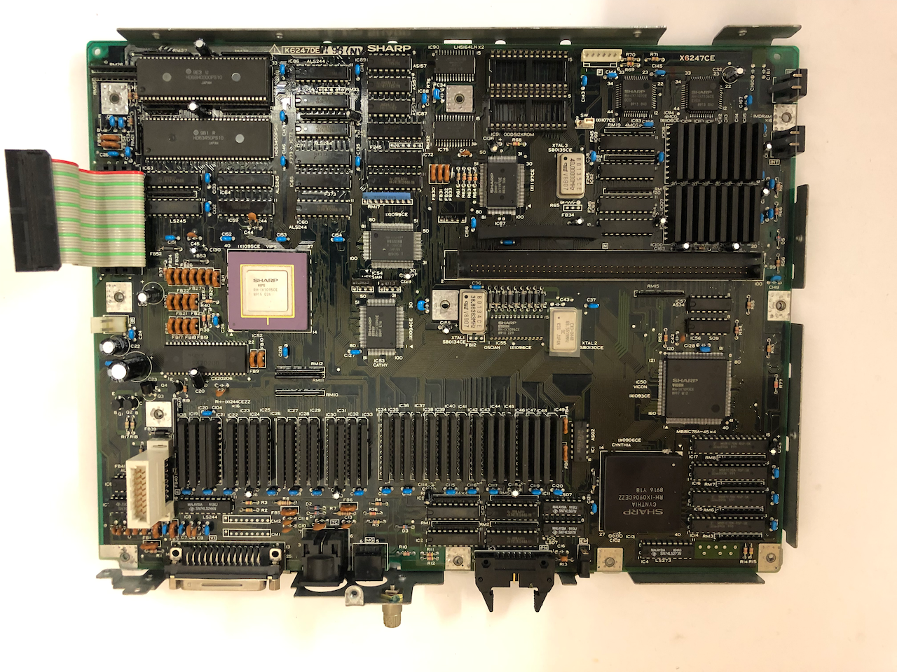
There are 3 main boards to consider for renovation, the motherboard, I/O board and the video output board. All are full of capacitors and the electrolytics have done well considering the MTBF for some are advertised as 2000 hours at 60-80'c and if there is any slight leak in the casing then they will dry out and lose performance (some go open circuit) much more quickly. The capacitors of real concern though are the tantalum bead capacitors, when they fail they go short circuit and cannot tolerate any reverse polarity and often have to be overrated for the expected voltages. Sharp no doubt have done a good job and the school of thought is to leave them, to replace them with modern equivalent or replace them with modern electrolytics. Leaving them untouched may work for many more years but should one fail with close proximity to memory and custom IC's then the instanteous short circuit of a tantalum failing prior to the PSU shutting down may be enough to damage the IC's. If you read up on any of the radio/tv engineers tantalum experience, or engineers repairing sensitive equipment such as oscilloscopes, they fail quite often and the school of thought is to replace them with electrolytics. I decided based on what I had read that the best course would be to replace all capacitors with modern electrolytics which will hopefully prolong the life of these great machines.
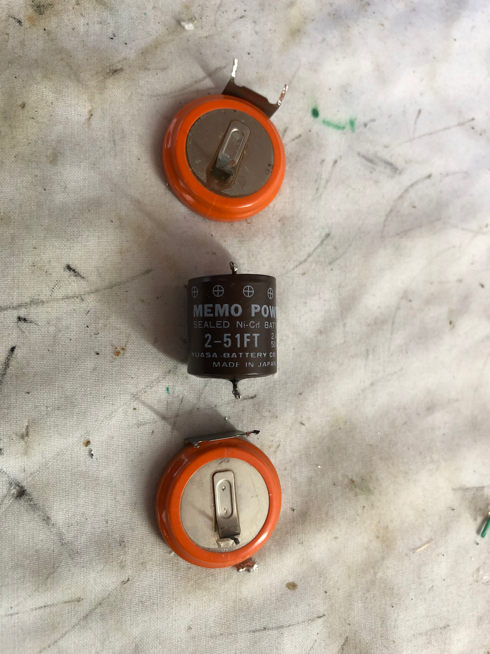
Another area of concern and one which has seen many machines end up on the scrap heap is the NiCd battery. Some batteries coming to end of life will leak and this acid seeps along the PCB disolving and corroding lands, pads and components. This machine was lucky to be using a more 'safe' battery and no damage had occurred. I replaced the CR2450 battery with the same model.
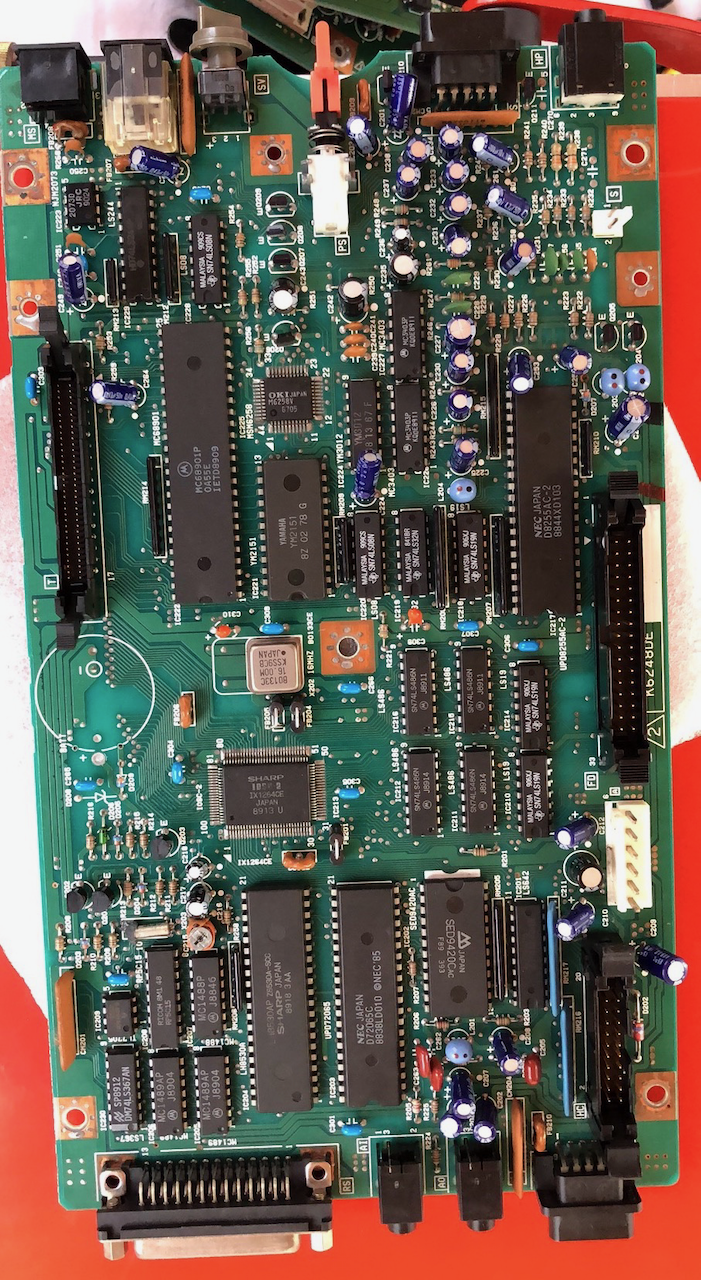
I/O board with the original capacitors.
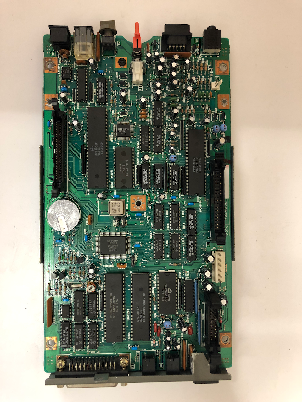
I/O board after capacitor and NiCd battery replacement.
The original batteries, the orange coated CR2450’s belong to the X68000, the brown NiCd belongs to an MZ-2500 which suffers similar fates when they leak.
Motherboard after capacitor replacement.

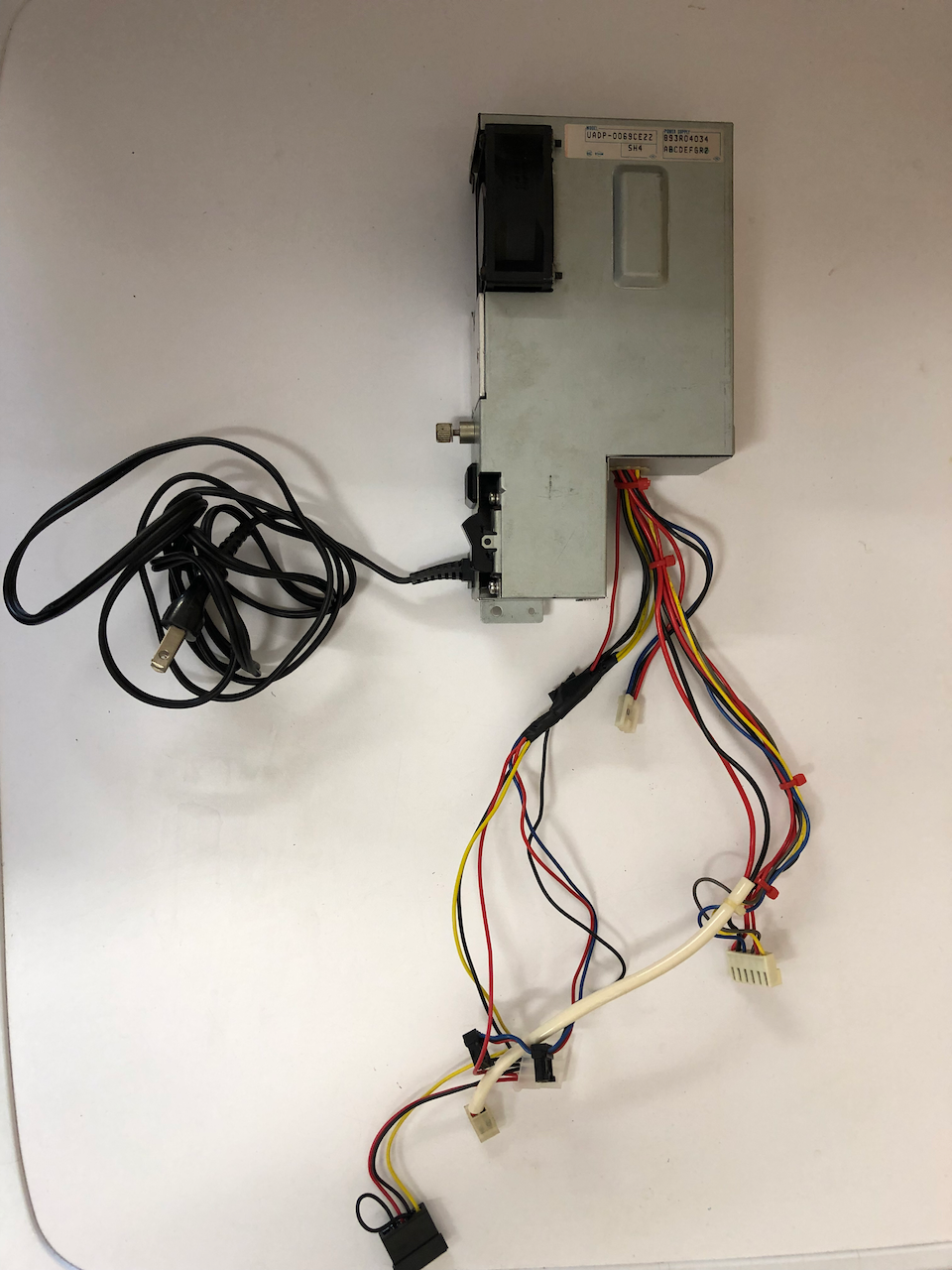
Power Supply
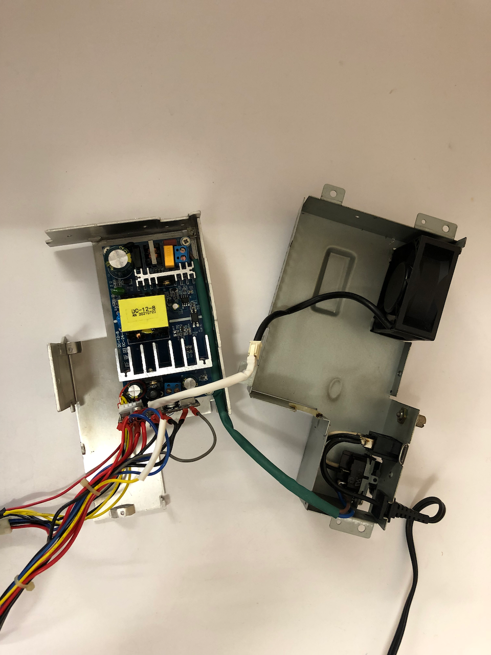
After studying requirements and alternatives I decided to go with a full internal replacement of the original PSU mainboard. This would leave the machine externally no different to original but have the added advantage that it could be powered not only from the original 100V AC but all other common mains supplies.
As multi-rail PSU's matching the X68000 requirements (Stand by 5V, 5V, +12V, -12V with soft power on) were not common for the given dimension restraints - PC ATX power supplies were technically suitable apart from the inverted soft power on enable signal, they were too large in dimensions - I opted for a high current, 8A +12V switch mode PSU with a good reputation and a pico-atx converter which converted +12V to all required PC voltages of which the X68000 shared in common.
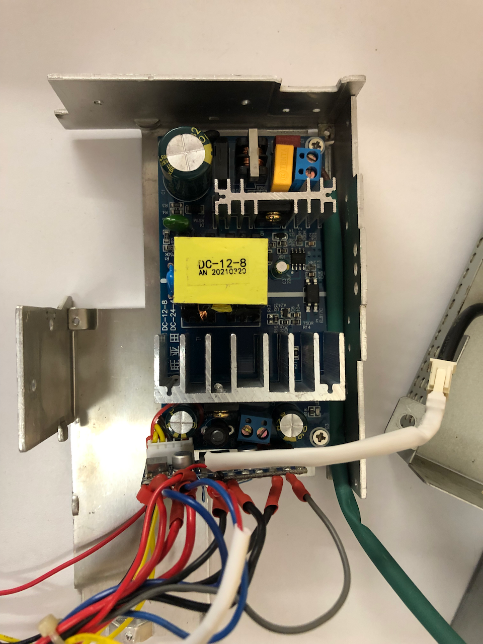
The chosen unit came from AliExpress, a +12V 8A switch mode PSU with an 85V-260V AC input range. The dimensions of 106.1mm x 57.1mm meant it would fit comfortably
within the original PSU casing.
The Pico-ATX convert chosen was a 160W unit, driven by a +12V/8A input left plenty of headroom for any and all of the X68000’s machine requirements.
Next, looking at the casing I worked out the best position for the PSU board to be placed. The original holes couldnt be used so I had to drill countersunk holes as this board needs firm grounding it cannot be left to float.
The next step was to work out the location for the pico-atx converter. As it happened, removing the ATX plug and with thick, stiff wire (as used by 10A diodes), the pico-atx would neatly fit into the screw connector of the +12V secondary side of the PSU.
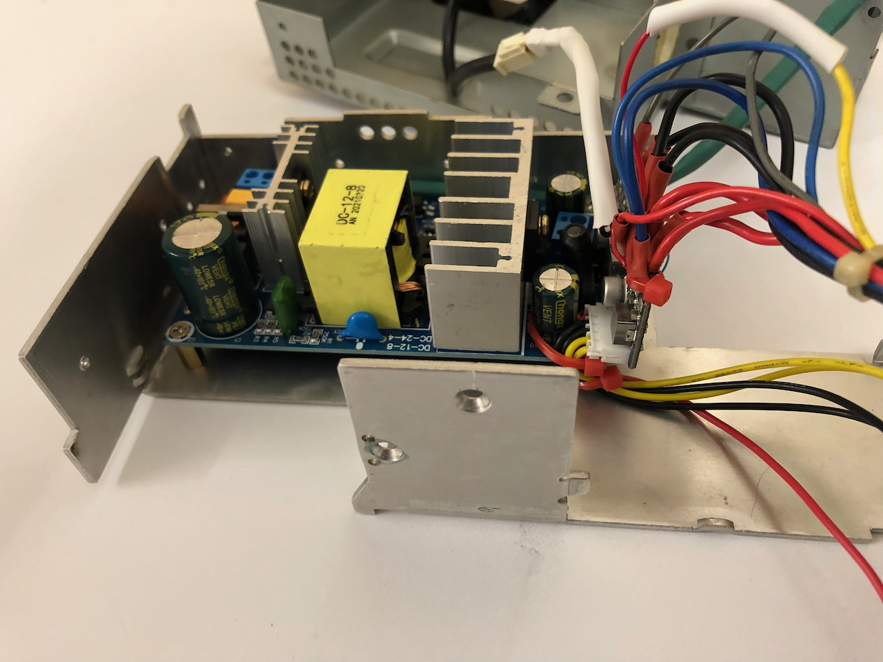
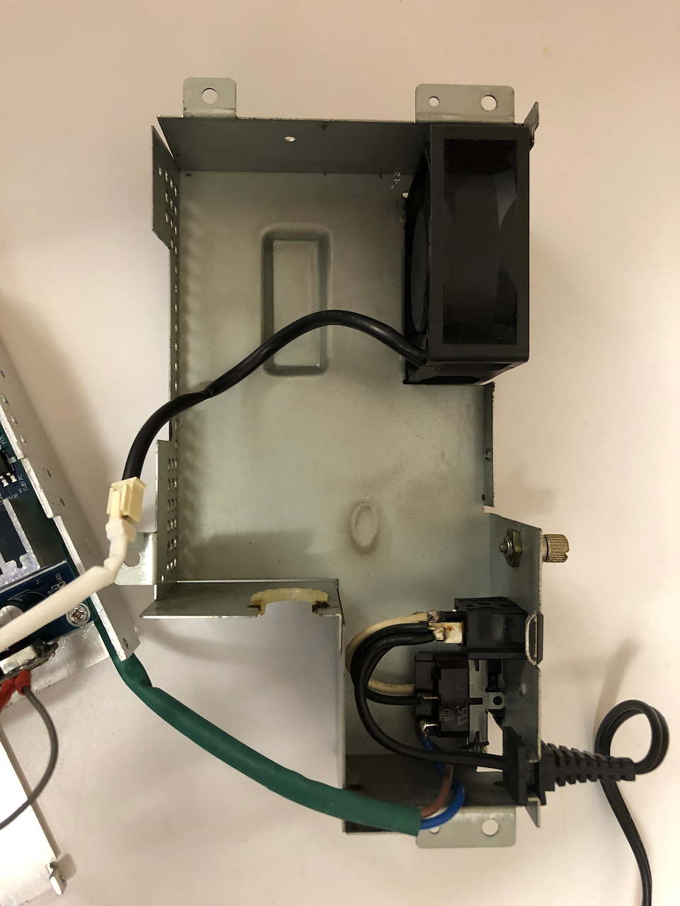
Wiring of the mains socket to the primary side of the PSU was achieved through double insulated 2 seperate core wires from the input connection to the PSU terminals.
The original fan connector was reused as was the original wiring loom, the thick stiff pins, with a bit of tensional support affixed nicely onto the pico-atx fan-out pins.
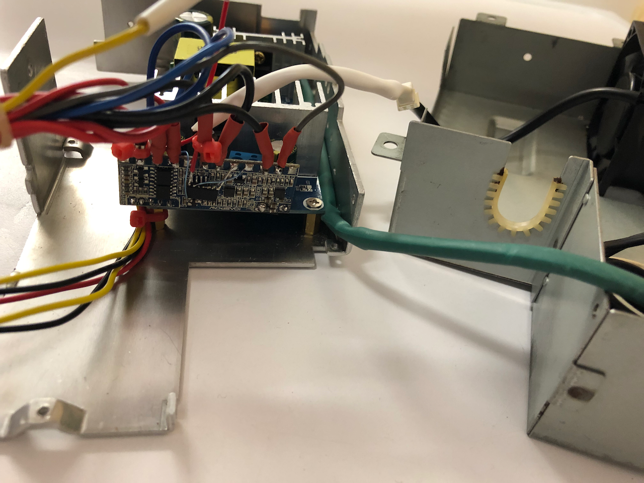
As the pico-atx uses reverse polarity for soft power-on compared with the Sharp X68000, an inverter needed to be added. Using an SMD part this was conveniently placed on the pico-atx circuit board. The circuit can be found here on the NFG Forums which also details another way of repairing the PSU.
Re-assembly
The X68000 casing is quite complex and piecing it together can be tricky. So I’ll write the steps below as a guide to assembly if you find yourself in the position where you’ve taken the X68000 apart and arrived at a point where your not sure of what goes where!
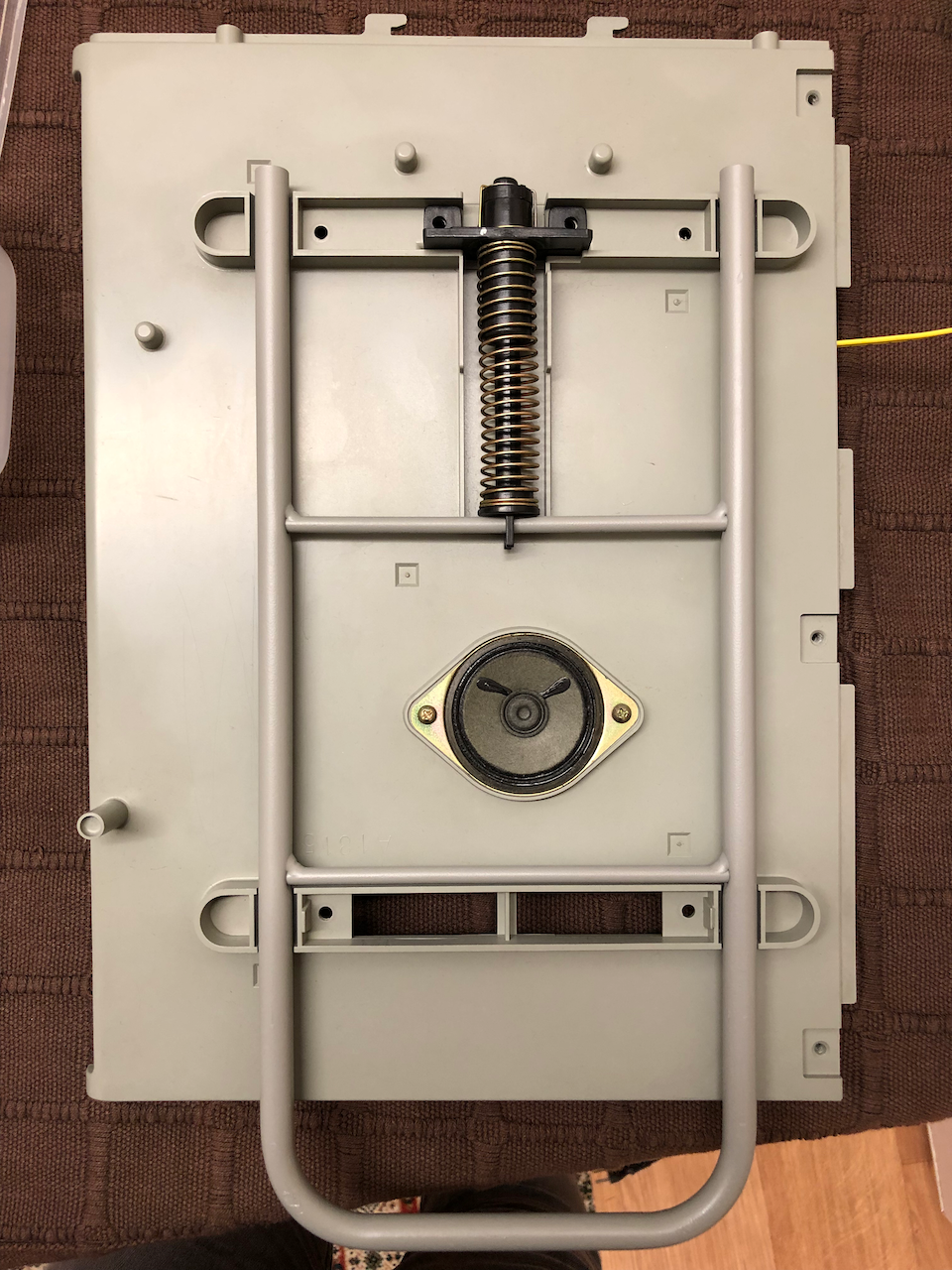
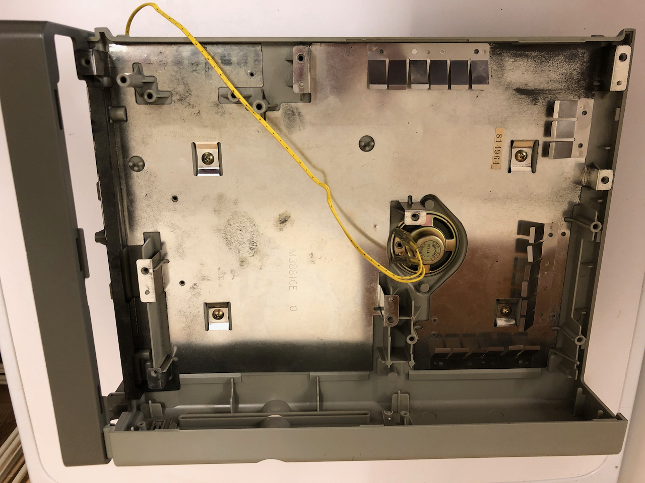
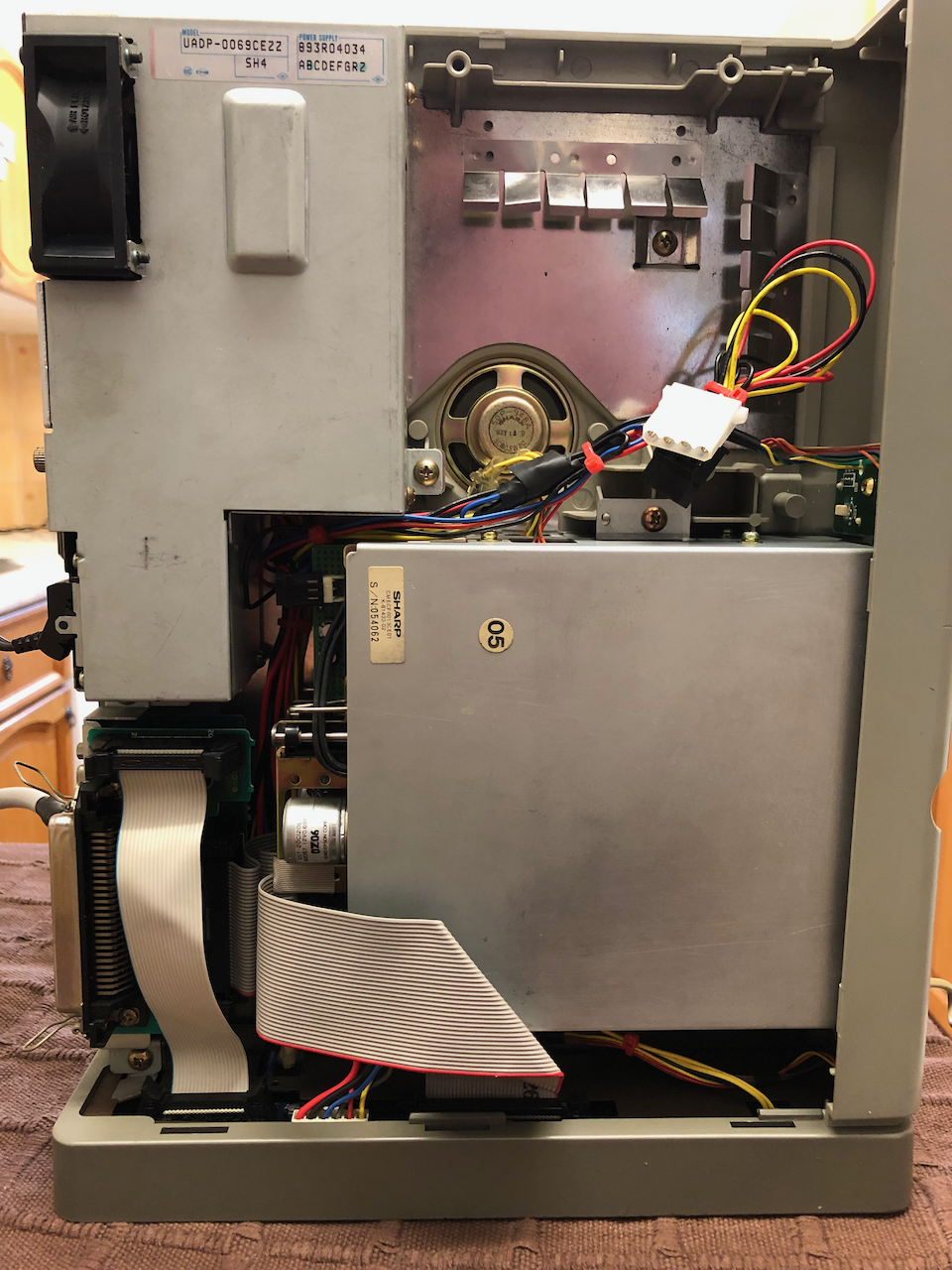
First step, secure the loud speaker and the carry frame and spring damper (the photo doesnt show the rubber endstop but this can be placed in later).
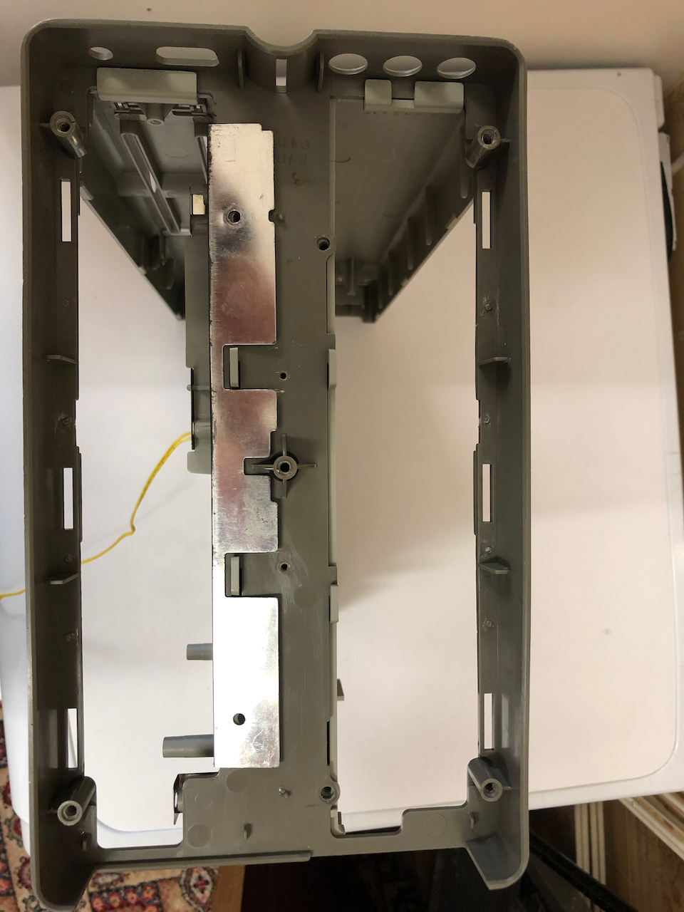
Attach the steel support bar to the opposite tower side.
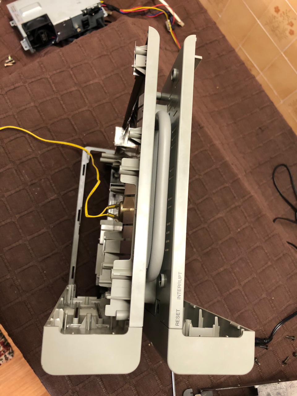
Attach the two front facia panels and the base panel to the sides above. Do not place all screws in at the moment, only the screws which secure the carry bar damper to the side panel and the two small feeler type metal compression pieces as can be seen in the photo below.
This should be the result, the two inner side pieces clipped to the base and the fascia panels screwed into the sides.
Top view when the fascia panels are attached to the inner two side pieces.
Place the speaker side RF shielding and secure with 4 large self tapping screws, this also secures the 2 side pieces together.
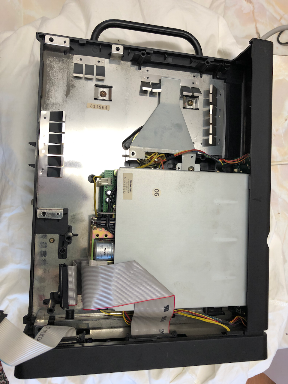
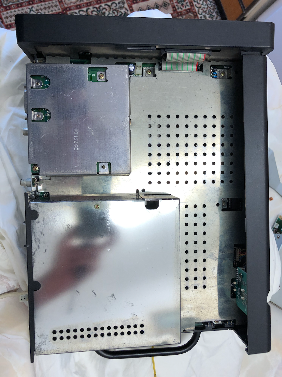
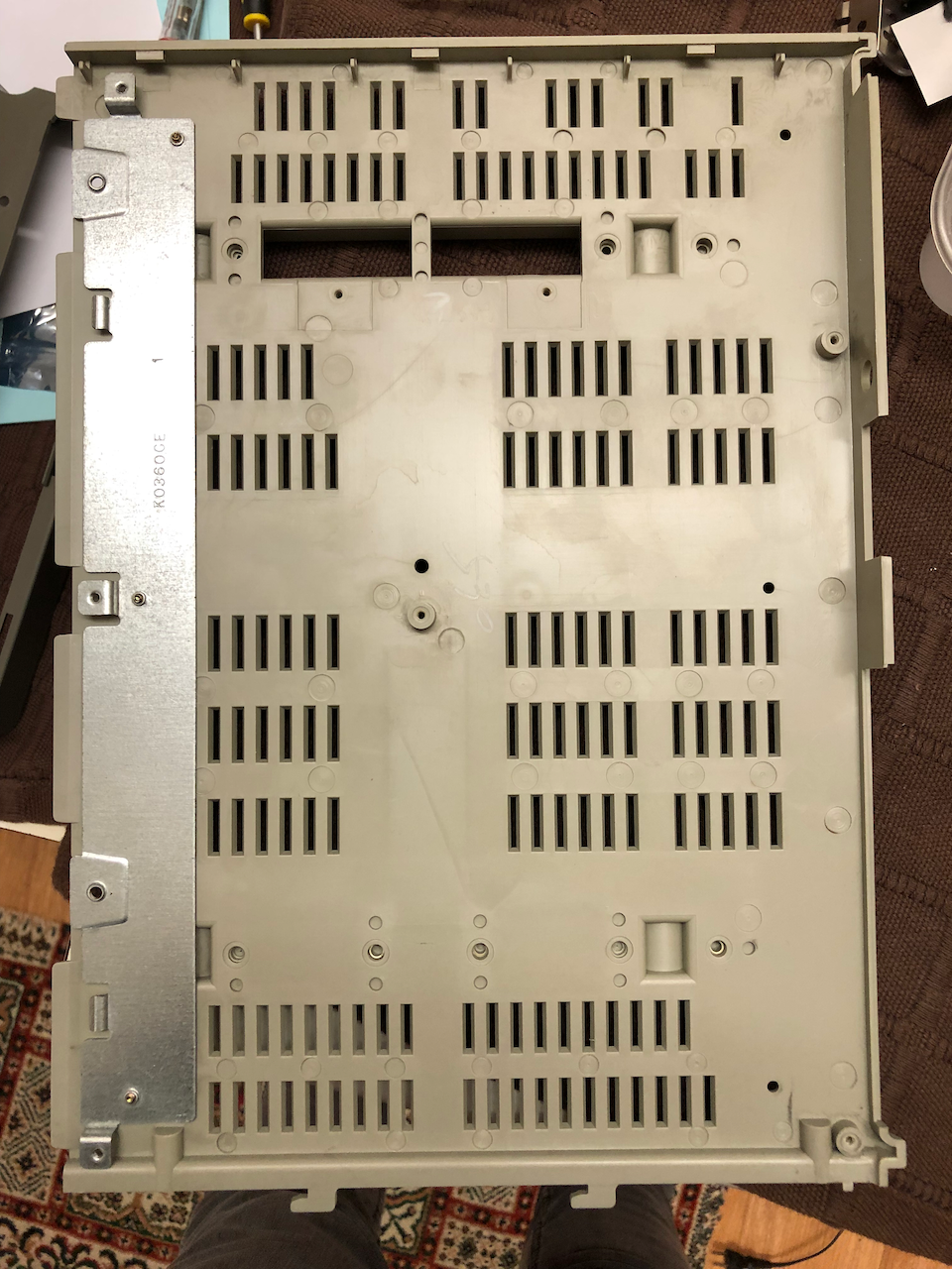
Underside view when the speaker side RF shielding is in place.
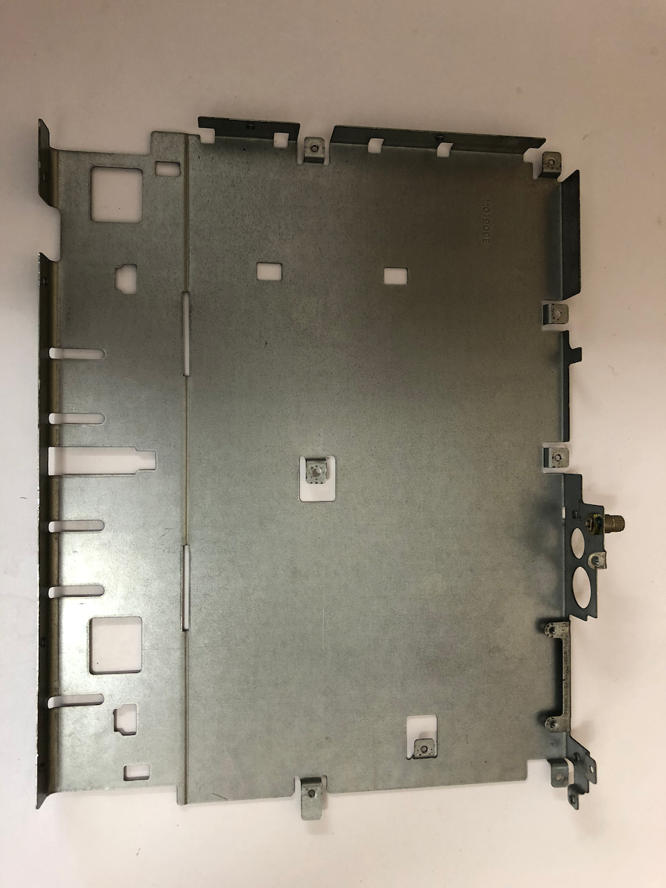
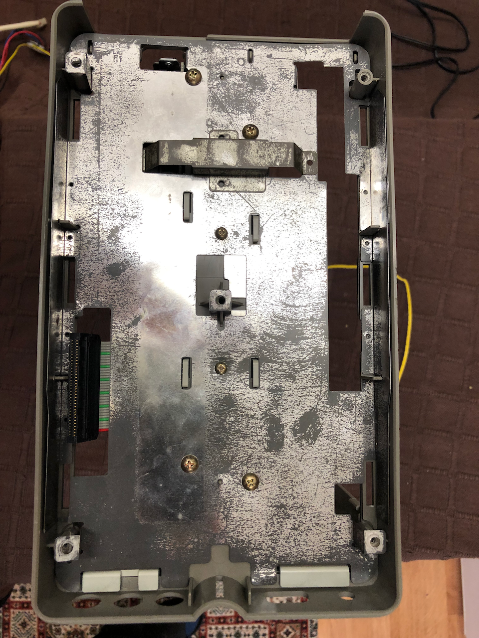
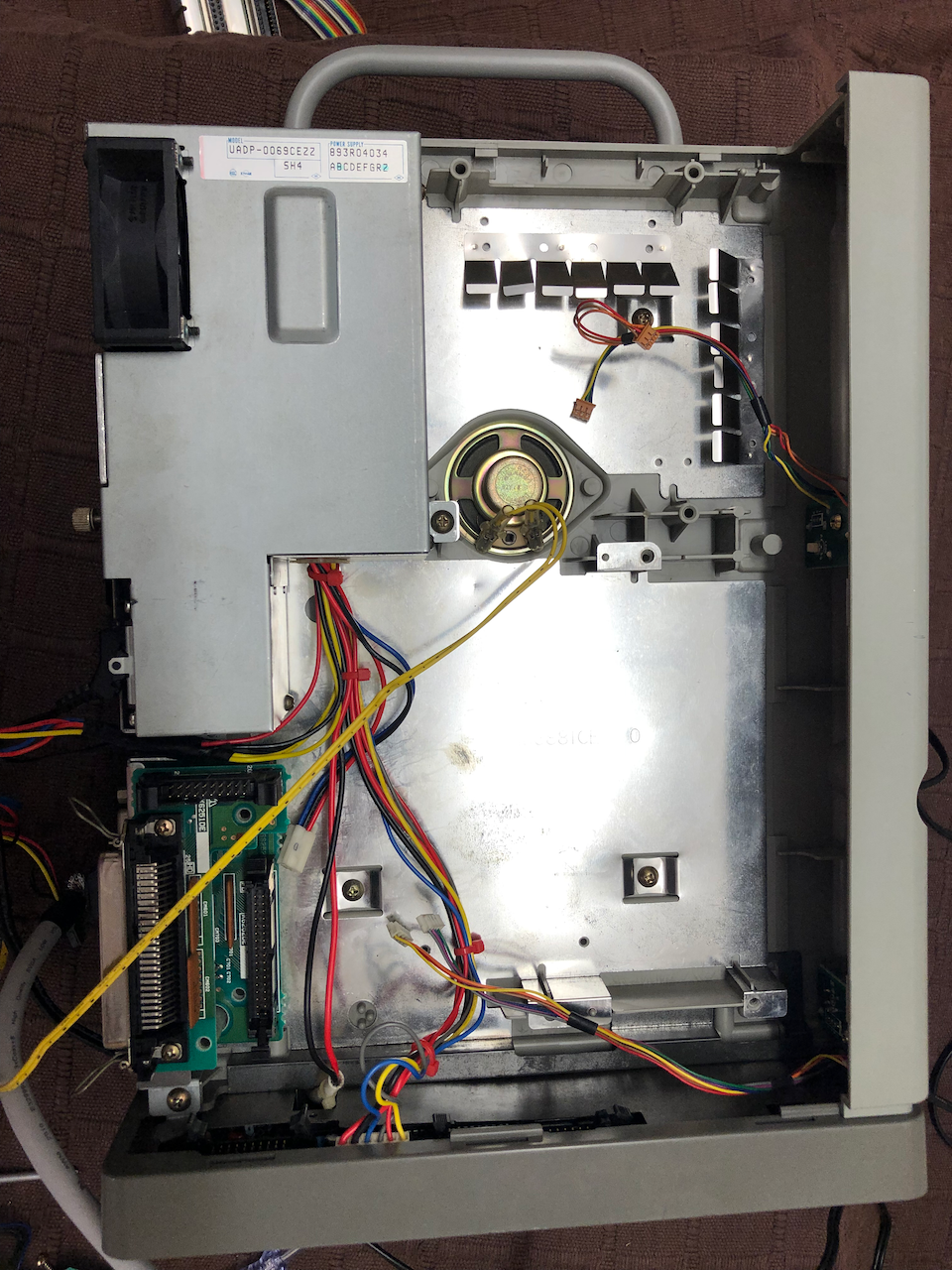
Take the solid metal subframe.
Take the motherboard.
Install the motherboard into the solid metal subframe and then place the top side RF shielding over it. Secure the shielding on the edges, screw holes can be seen (ie. threaded holes) for this purpose.
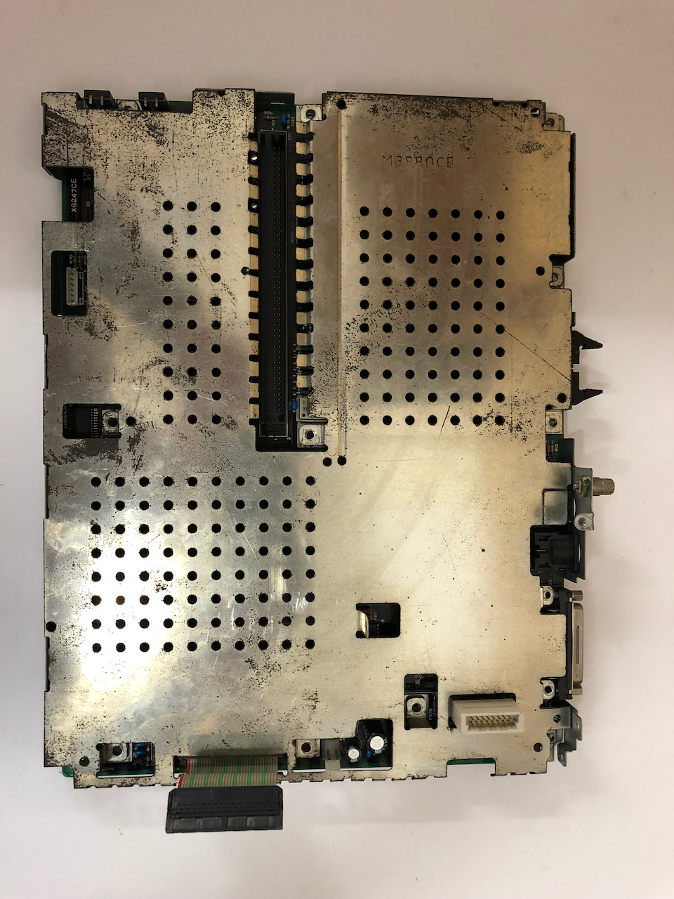
Underside of the metal subframe with the motherboard installed.
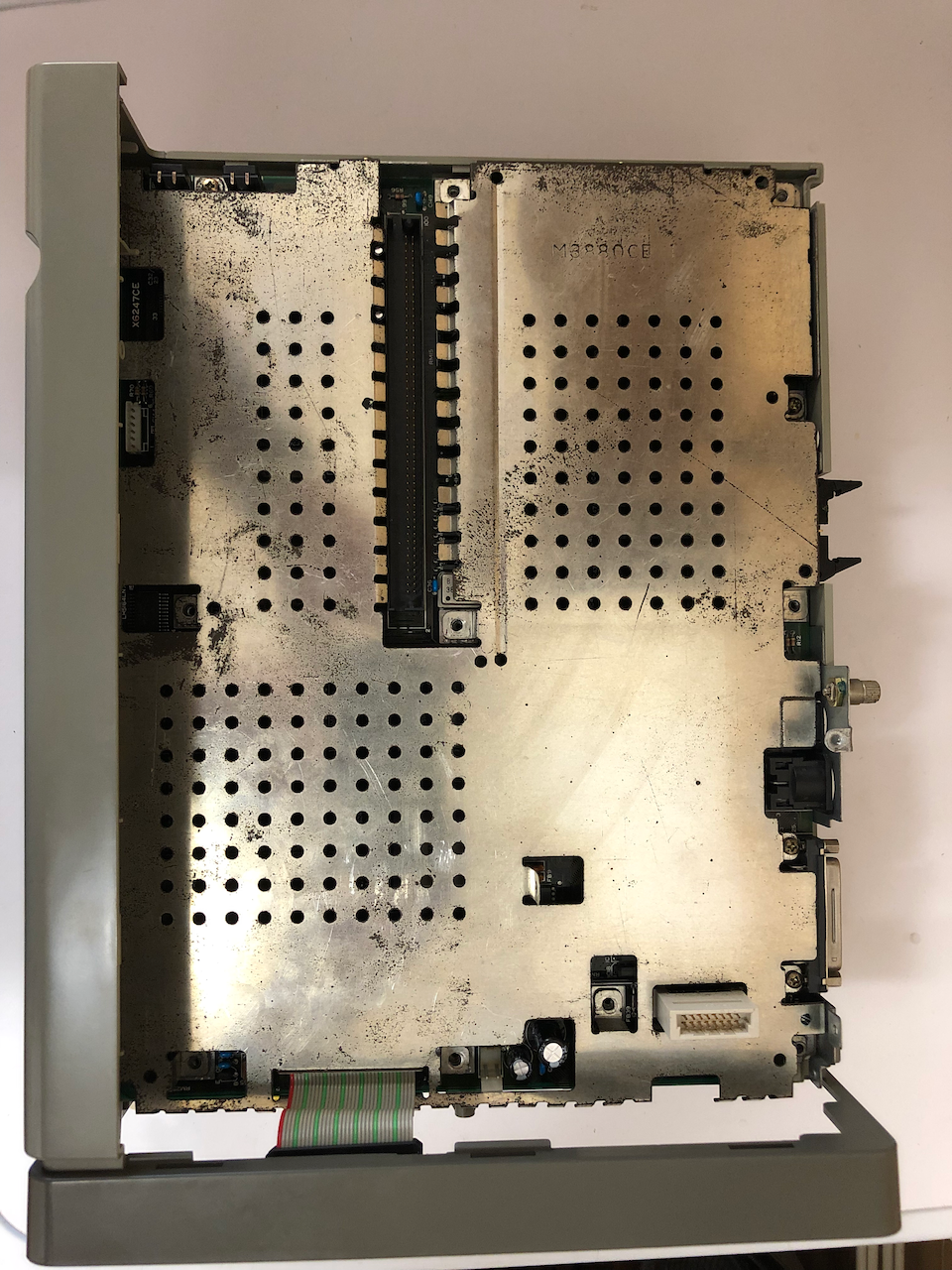
Install the metal subframe, motherboard and RF shielding as one unit into the casing, opposite side from the speaker. Secure with screws on the fascia panel side only.
Place the expansion cage onto the board expansion socket and secure with screws in each corner. The screw in the center should be a self tapping screw.
Install the RF shiedling over the expansion cage, secure with 4 screws at the cage top both top and bottom sides.
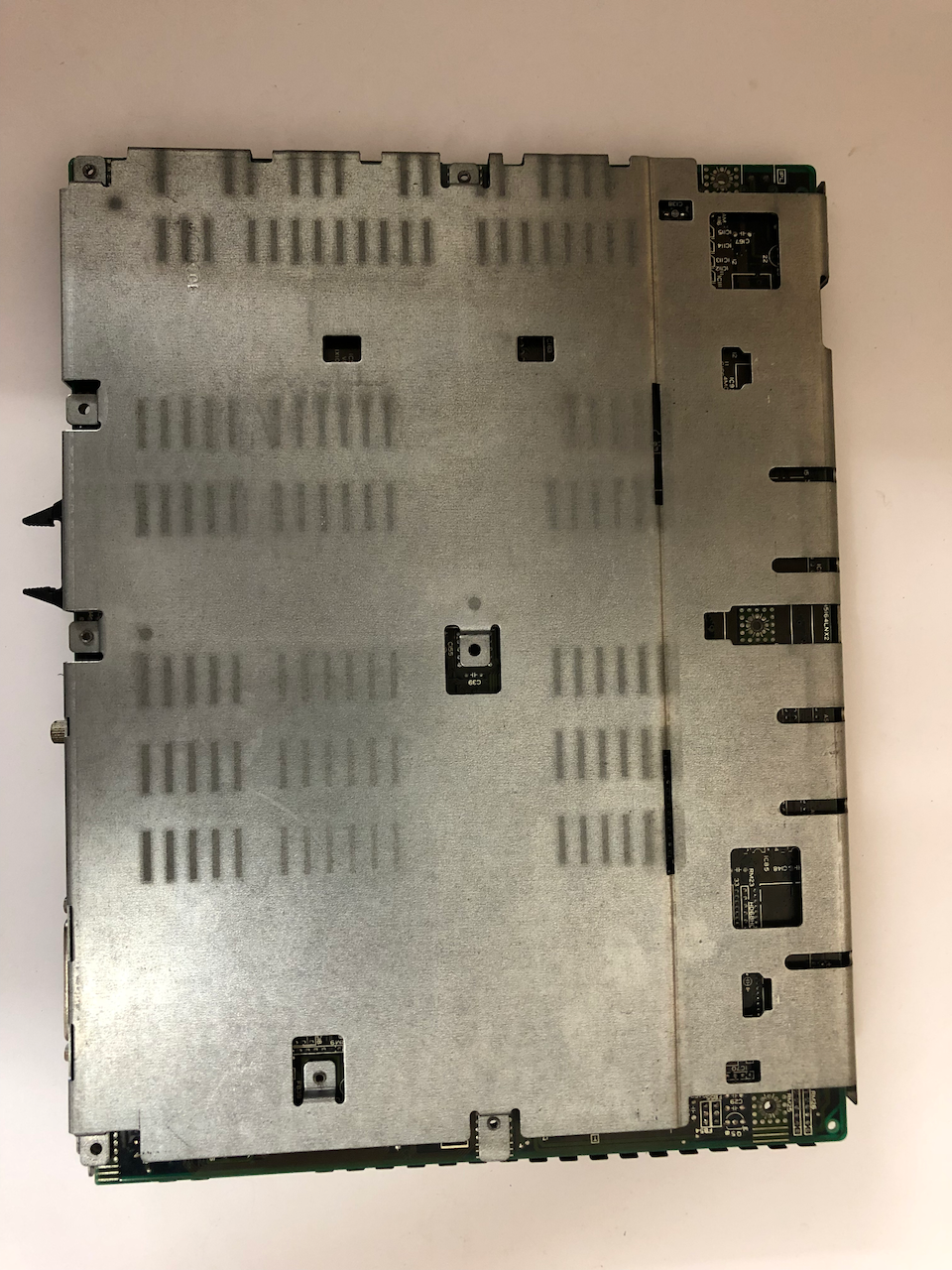
Top side view when the expansion cage and RF shielding is installed.
Assemble the Video modulator board into its RF shielding frame. Next to the motherboard connector (white connector rising from the motherboard), install the large 20+mm standoff into the screw hole. Plug the video modulator module into the connector and secure
to the motherboard and casing.
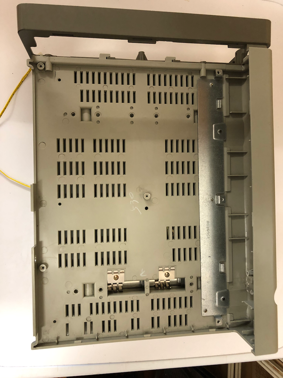
Turning to the I/O board, on the underside of the casing install the RF shielding and secue with 6 screws, The original installation had melted plastic holding the edges to the casing which arent really necessary, would have been a manufacturing aid.
Take the I/O expansion board and install it into the bottom metal subframe/external casing base. It requires two screws on the RS-232 D-SUB connector to hold the I/O board onto the subframe and also a screw by the power on button.

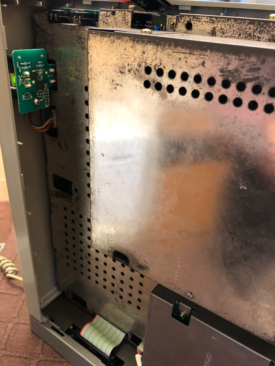
Power LED daughter board installed on the fascia.
Install the I/O expansion/subframe into the casing base and secure with 5 black self threading screws.
Connect the power lighting board to the fascia and connect to the motherboard by the 7 pin connector. Connect the mainboard I/O expansion bus to the I/O board.
Ready the Power Supply.
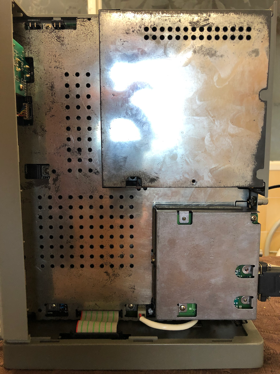
Install the power supply and fasten it down with the top 2 and opposite speaker self tapping screws.
Installed PSU as seen externally.
Fasten the external floppy/SASI/SCSI expansion board onto the casing, one screw is shared with the PSU. Route the two wire 5V cable (longest with a white sleeving) through the channel in the motherboard which feeds under the I/O board to the opposite side
where the motherboard resides. Plug it into the motherboard. Connect the 6 way power connector from the PSU to the I/O board. Install the Floppy activity board and eject button board onto the fasica panel. They only fit in one place and require 1 self tapping
screw each to secure.
Install the floppy disk cage containg the two floppy drives. Connect up the activity led connectors (near the speaker) and the eject button connectors which are on the floppy cage near the I/O board. Connect up the 34pin floppy disk cable to the floppy
expansion board, both floppies and the 34pin floppy connector on the I/O board. Connect up the two 3pin black power supply connectors to the floppy drives.
Connect the SASI/SCSI cable from the I/O board to the floppy/SCSI/SASI expansion board. Tie up the cables with cable ties.
Tidied up cables ready for casing closure. Add the left and right outer casings and secure with screws to complete assembly. Note the standard 4 pin power connector used on IDE/Floppy drives, this has been added in case of future expansion with a SCSI2SD or
non-Sharp SASI drive.
I didnt take any photos of the keyboard renovation and re-assembly, this basically involved careful removal of all the key tops, wiping the circuit board in Isopropyl alcohol and using switch cleaner in each of the cherry style key switches then reassembling the keytops and unit.
It would be good practise, once the PSU has been installed and connected, to power up to ensure that everything is ok, you should see the VGA display start up and the message to insert a floppy disk appear.
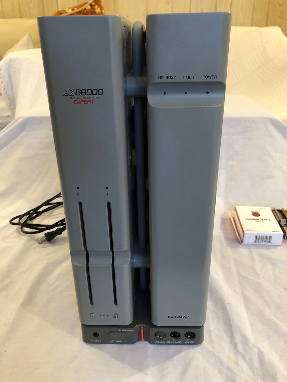
The finished machine
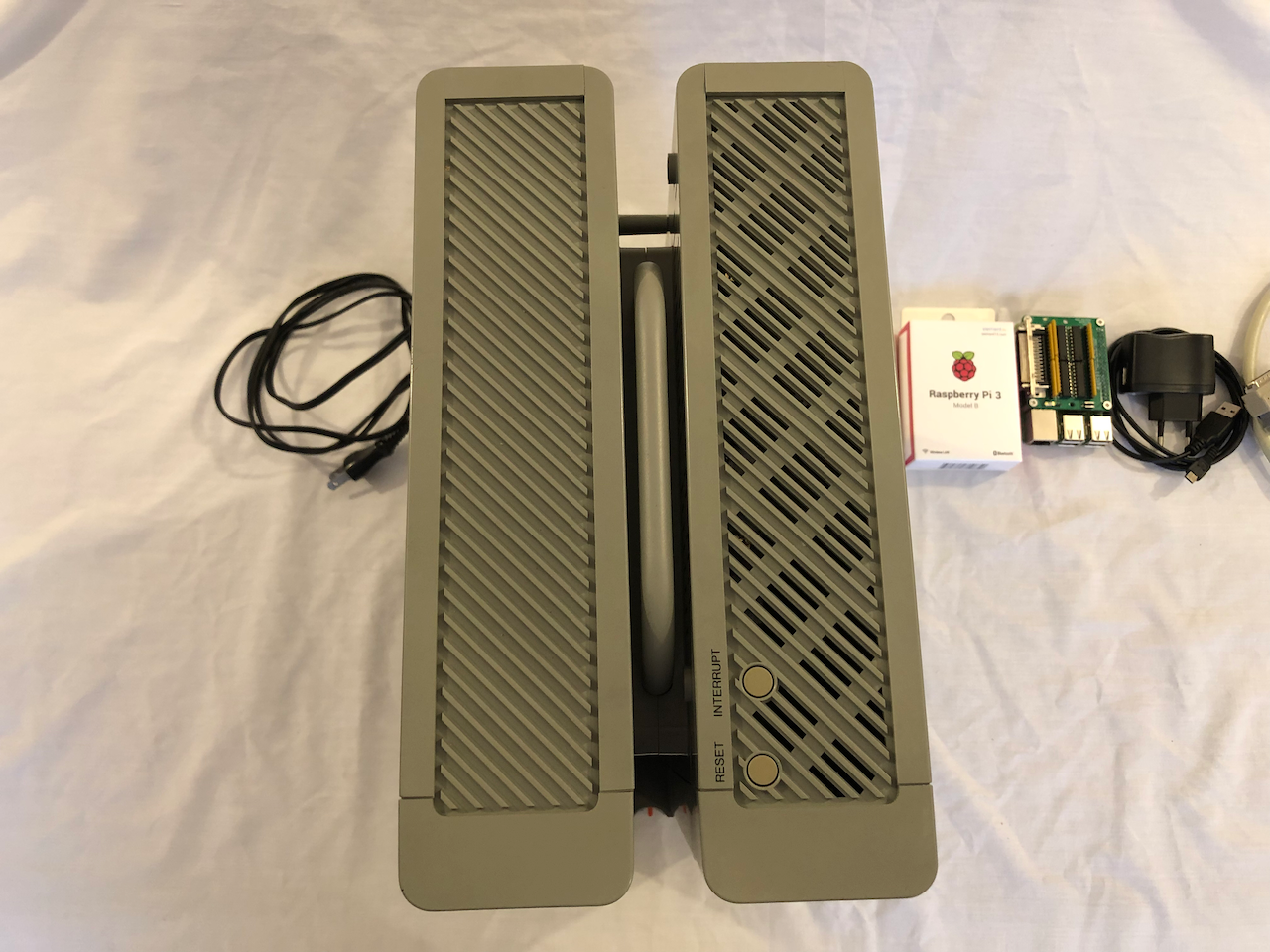
Front Panel
Top View.
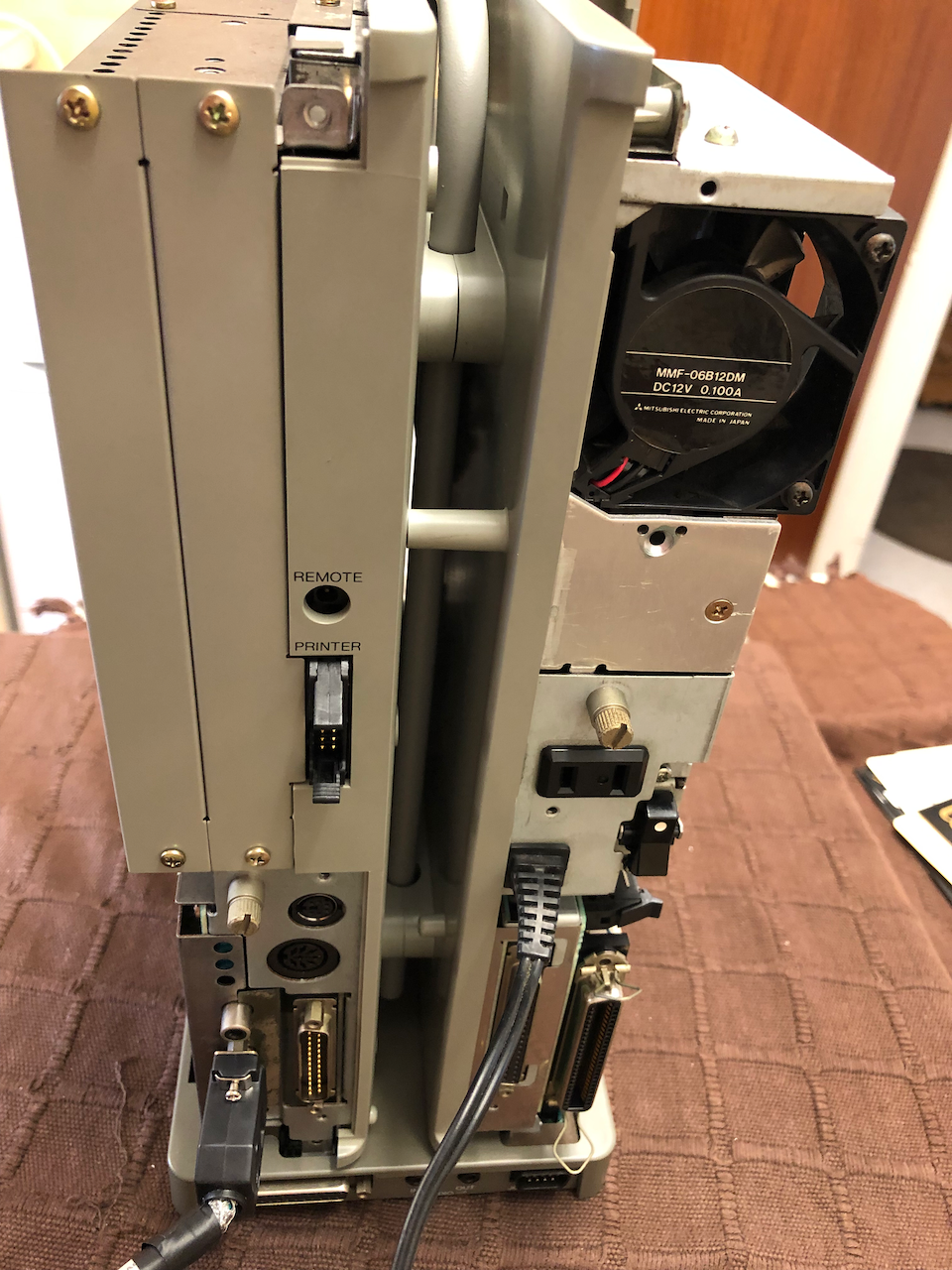
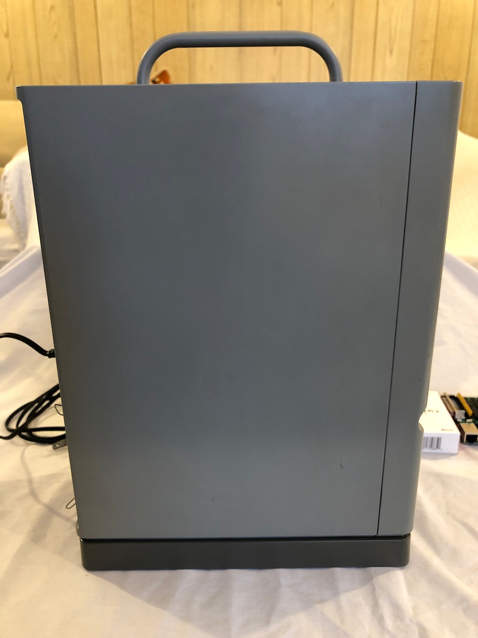
Left tower view.
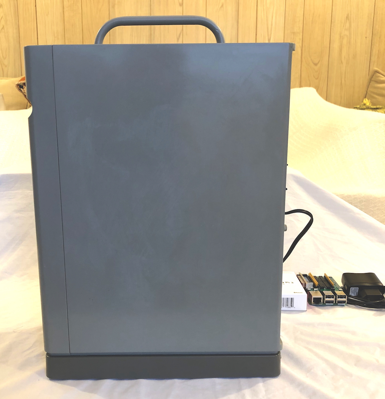
Right tower view.
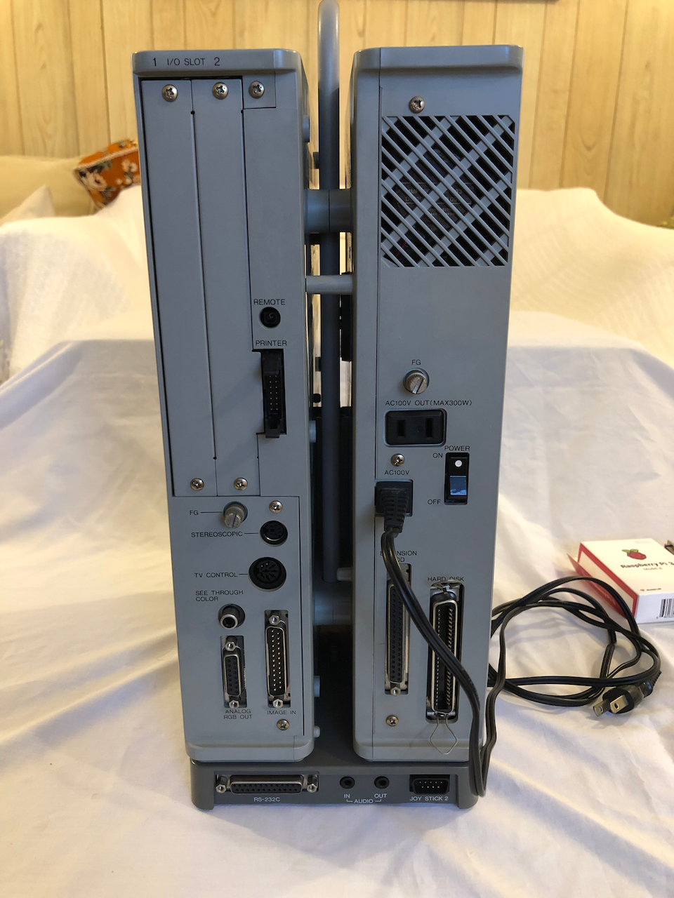
Rear view.
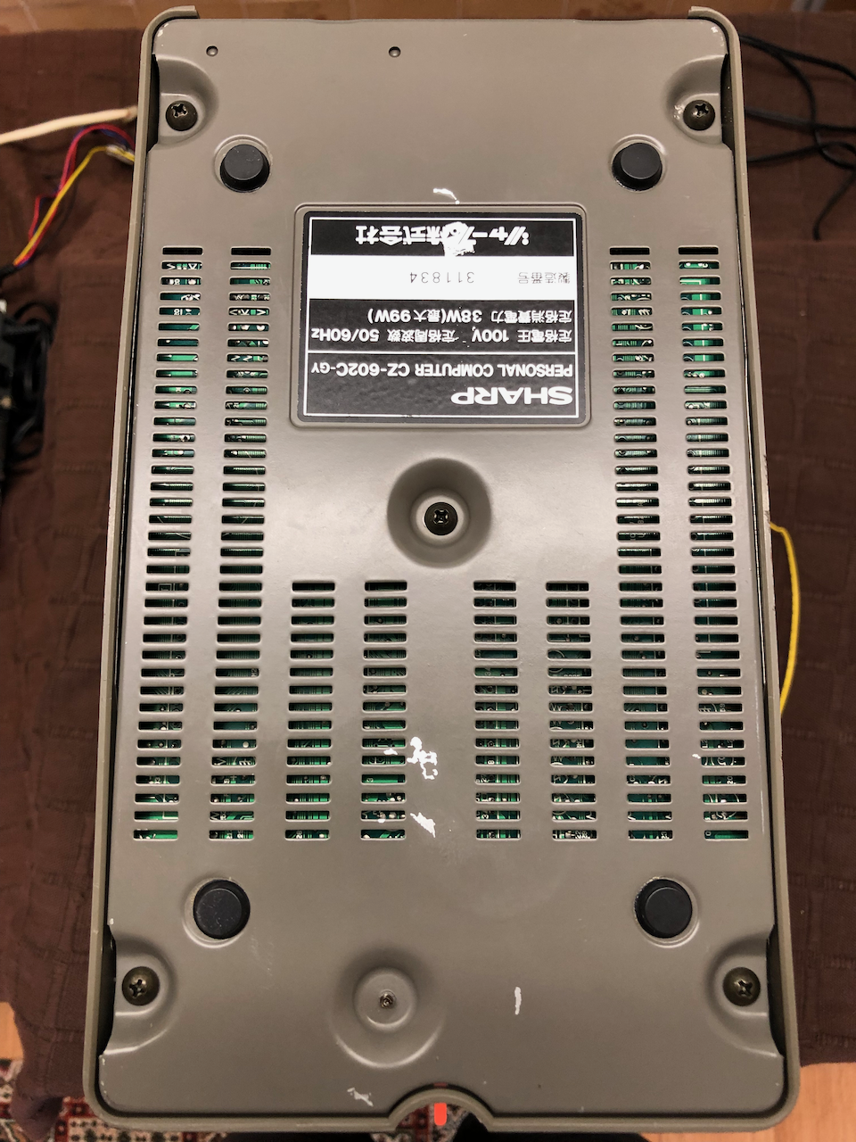
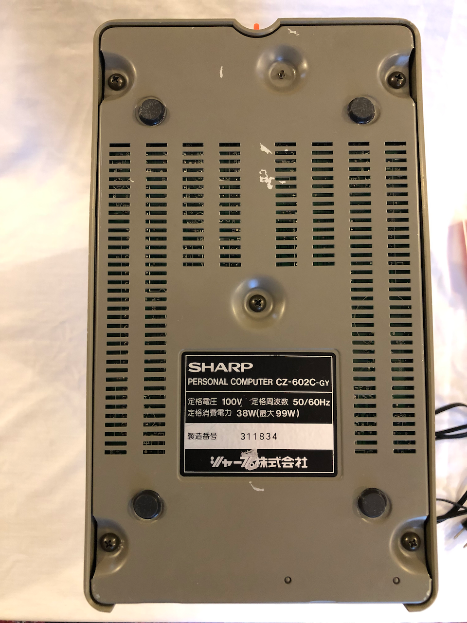
Underside view.
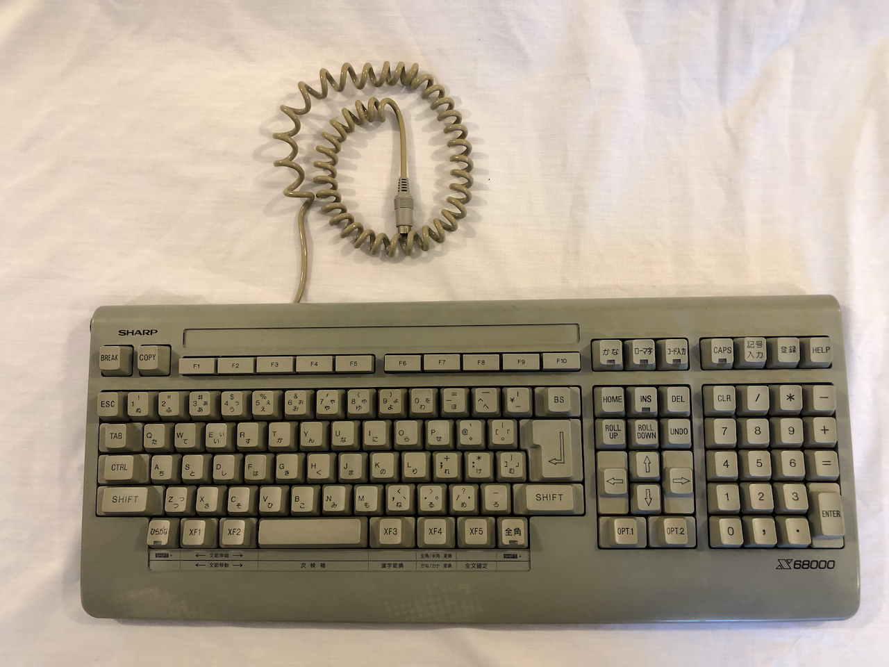
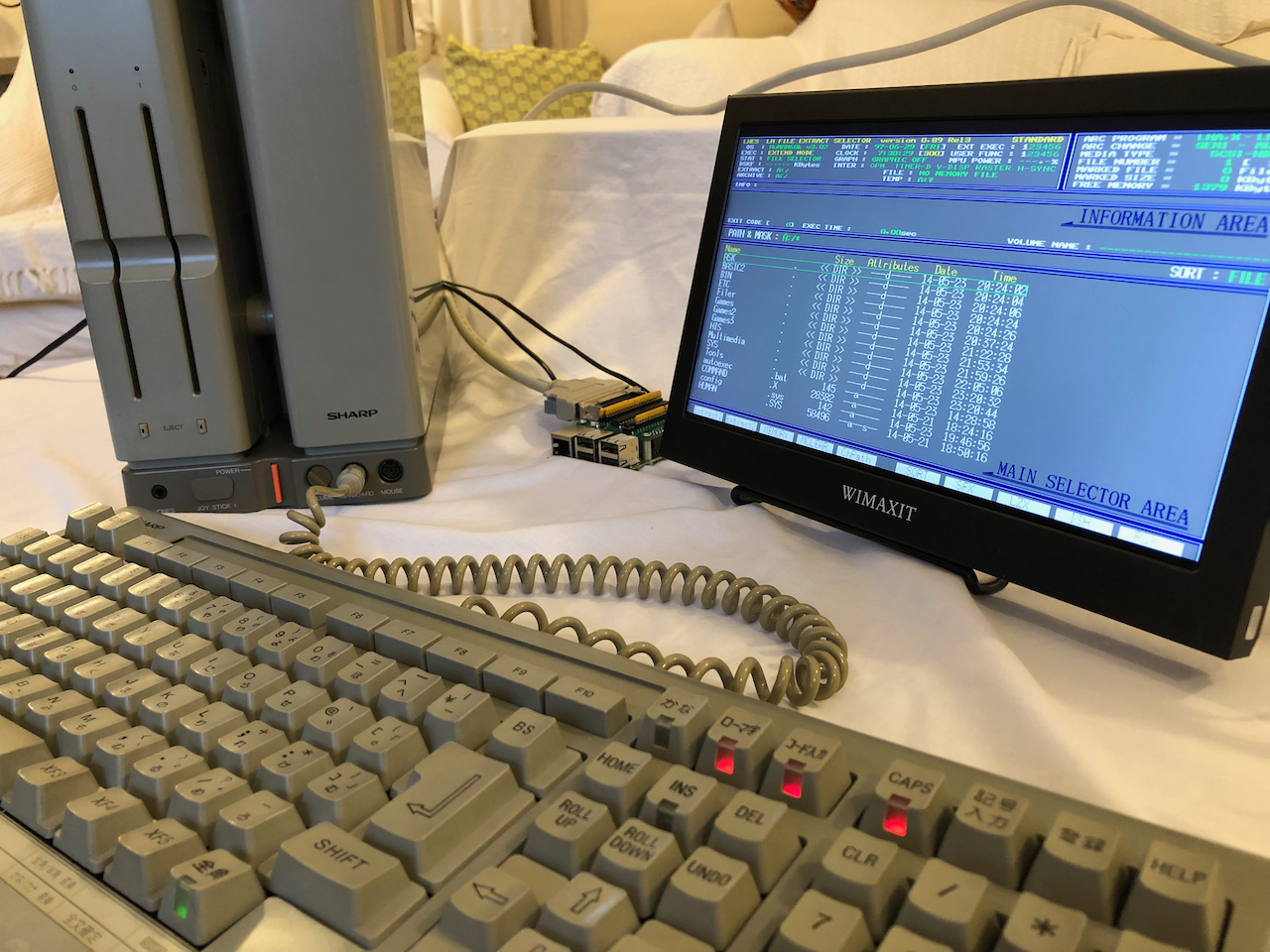
Keyboard top side.
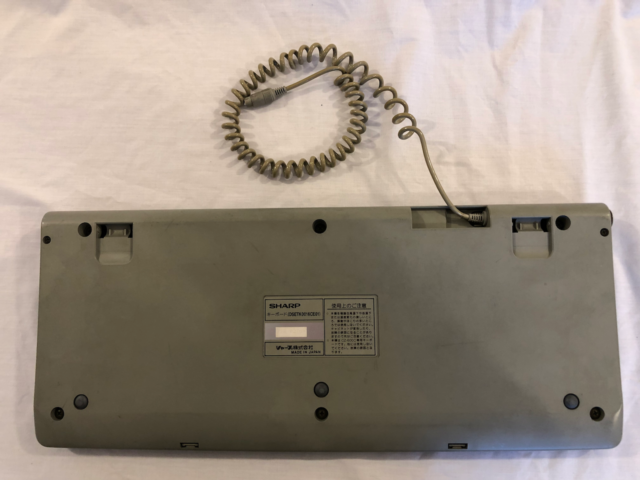
Keyboard underside.
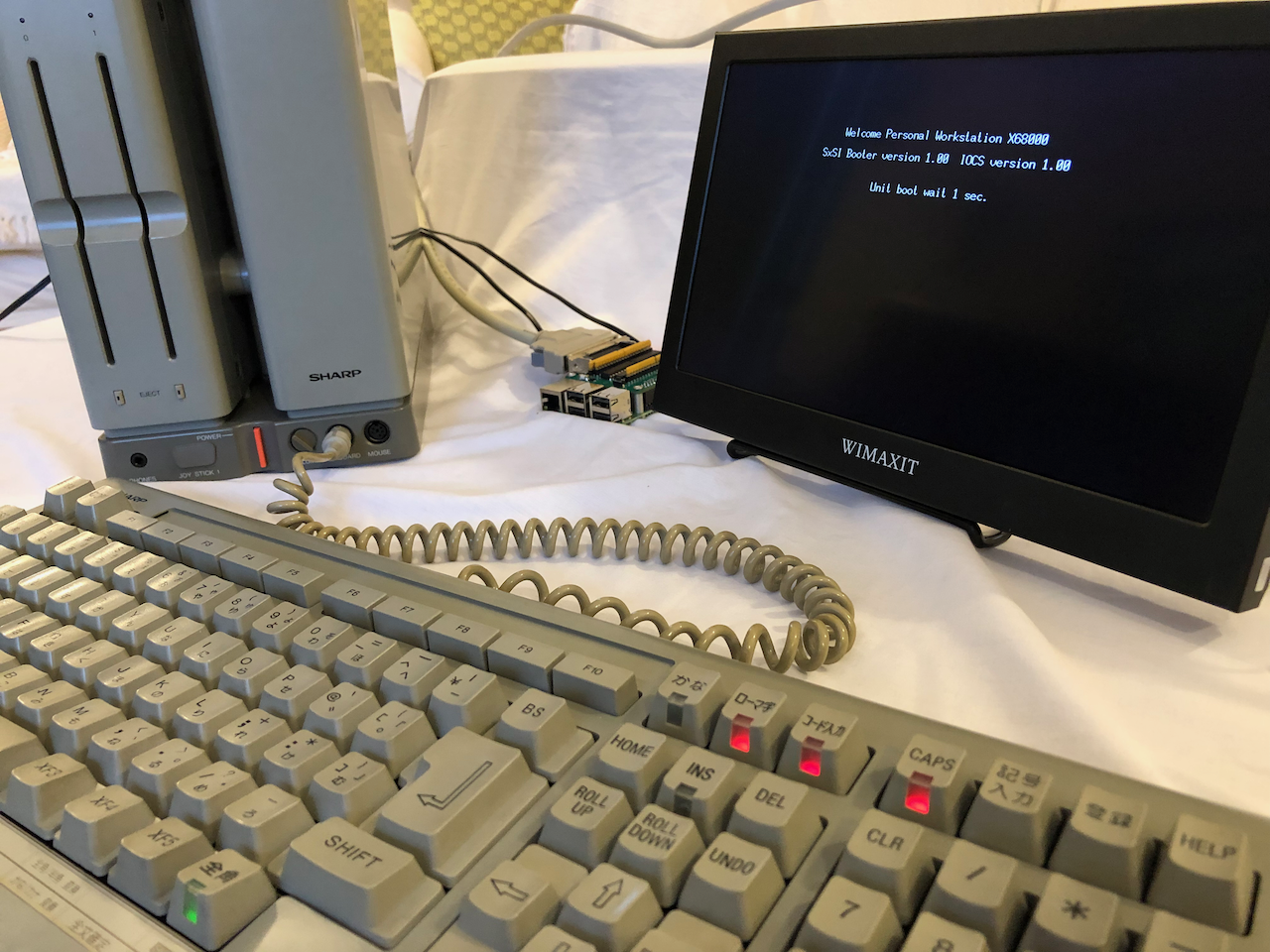
Power on after installing the Raspberry Pi RaSCSI hard disk emulator. As this is a SASI based unit an initial boot by floppy is required to configure and install a non-volatile driver and after subsequent power cycles the floppy disk isnt required, it
boots directly from the hard disk.
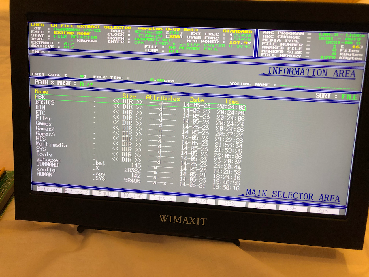
The NFG Forums hard disk compilation V4 menu.
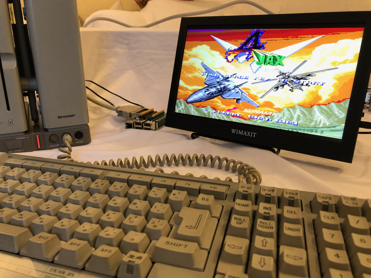
Lastly, a game demonstration, A-JAX which is provided on the V4 compilation.
Next task, the X68000 Expert HD….
Credits
Licenses
The Gnu Public License v3
The source files are distributed in the hope that it will be useful, but WITHOUT ANY WARRANTY; without even the implied warranty of MERCHANTABILITY or FITNESS FOR A PARTICULAR PURPOSE. See the GNU General Public License for more details.
You should have received a copy of the GNU General Public License along with this program. If not, see http://www.gnu.org/licenses/.