 SharpKey Multi-HID Interface Technical Guide
Overview
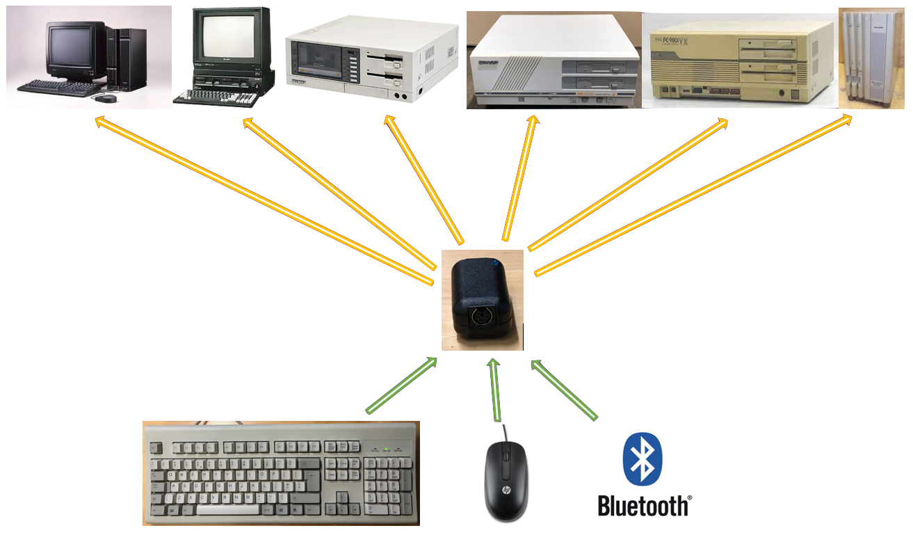
The SharpKey Multi-HID Interface is a device which enables connection of Keyboards and Mice, via PS/2 or Bluetooth, to vintage Sharp and NEC computers. It is
housed in a small KM-24 black or light-grey casing to match the host console colour and takes up minimal additional space. It has two external ports, one for a PS/2 keyboard or mouse and the second
for a cable to connect with the host keyboard or mouse input socket. If bluetooth is used, the PS/2 port is not used and only a host cable from the host port is required.
This document describes the technical detail of the hardware used to create the SharpKey, the protocols and all relevant information therein.
Protocols
This section details the protocols used by each of the host computers between the keyboard/mouse and main unit. The SharpKey replicates the protocols in order to convert a Keyboard or Mouse
PS/2 or Bluetooth protocol into the host protocol.
MZ-2500 Keyboard Protocol
The hardware interface comprises of 7 signals, 5V and GND using a shielded 8pin mini-din socket and plug, with plug wiring below.
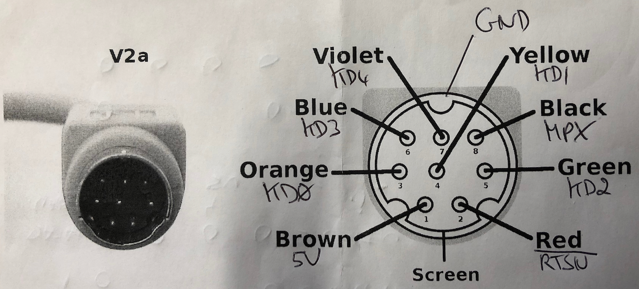
RTSN, KD4, MPX are output signals from the main unit side. KD [3:0] is a bidirectional bus between the main unit and the keyboard, direction under main unit control using RTSN.
| Signal |
Direction |
Logic State |
Description |
RTSN
Row Strobe |
Main Unit -> Keyboard |
HIGH (1) |
A Row address is being transmitted from the main unit to the keyboard. |
| |
|
LOW (0) |
The keyboard is transmitting requested data over the 4 bit bidirectional bus KD[3:0]. |
KD4
Type Strobe |
Main Unit -> Keyboard |
HIGH (1) |
The keyboard must return the actual key matrix data as referenced by the Row number. |
| |
|
LOW (0) |
The keyboard must return a logical AND of all the keys, ie. D0 = AND of bit 0 on ROWS 0 to 13, D1 = AND of bit 1 on ROWS 0 to 13 etc. |
MPX
Nibble MUX Strobe |
Main Unit -> Keyboard |
HIGH (1) |
The upper nibble of the requested ROW (or AND of row data as directed by KD4) is sent from the keyboard to the main unit. |
| |
|
LOW (0) |
The lower nibble of the requested ROW (or AND of row data as directed by KD4) is sent from the keyboard to the main unit. |
KD[3:0]
Bi-dir bus |
Main Unit -> Keyboard |
|
Active when RTSN = HIGH (1), transmits the 4 bit row number of the row data from the keyboard matrix. |
| |
Keyboard -> Main Unit |
|
Active when RTSN = LOW (0), transmits 4 bits of the 8 bit column data of the requested row. 4 bits is selected by KD4 & MPX. |
There are two main modes of operation, a test all (STROBEALL) keys mode, used whilst waiting for a key to be pressed which is followed on by a manual scan of all rows to retrieve column data to locate the pressed key.
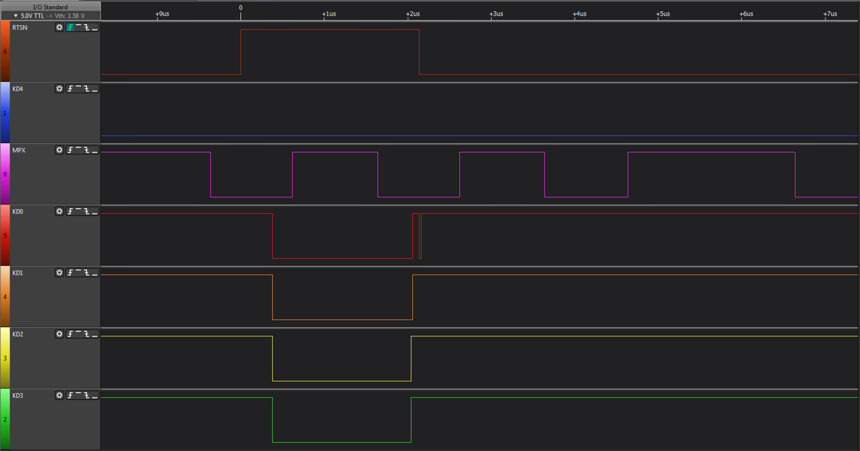
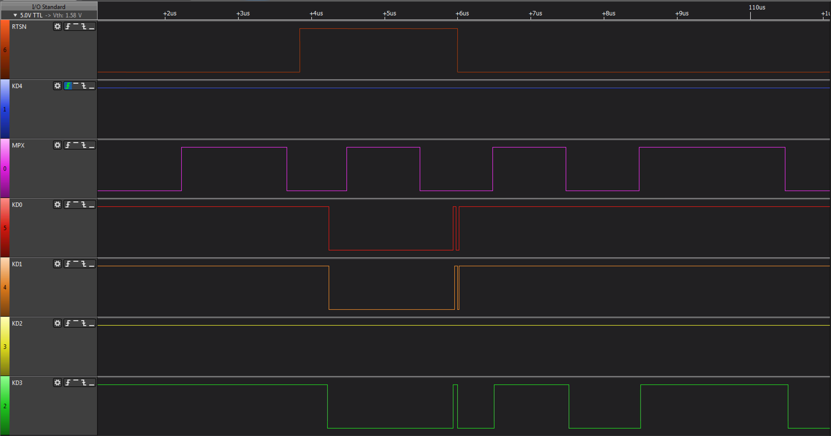
For key data retrieval the protocol is as follows:
- RTSN goes active HIGH and remains active for 1.08us. The initial RTSN period, after detection of a key via STROBEALL, is 1.08us active HIGH and 660ns inactive LOW. Thereafter the period is a uniform 660ns active HIGH and 680ns inactive LOW.
- The mainboard sends a scan row to the keyboard which becomes valid 160ns after the rising edge of RTSN.
- The scan row is read by the keyboard in the remaining 920ns from KD[3:0]. KD4 state (or state change) precedes the rising edge of RTSN, generally changes on the falling edge prior to the triggering active edge of RTSN.
- KD4 is sampled, when LOW the logical AND of all keys per column is set for retrieval, when HIGH the actual column of the selected row is set for retrieval.
- On the RTSN falling edge (RTSN goes inactive LOW), MPX goes HIGH for 320ns and the upper nibble of the data set for retrieval is output by the keyboard on KD[3:0] after 20ns from the MPX rising edge. The data is then read by the mainboard within the remaining 300ns before MPX goes LOW.. When MPX goes LOW ') the lower
nibble of the data set for retrieval is output on KD[3:0] with the same 320ns timing interval. After 320ns RTSN will then rise again.
- The above repeats whilst a key is being pressed, the row sent can vary or remain static, for example if reading the same key to determine bounce or repeat.
- If no key is being pressed, switch to STROBEALL mode.
For the STROBEALL mode, the protocol is as follows:
- During the STROBEALL mode, KD4 is held LOW and apart from a 20ns glitch which varies from 18.996ms to 198.83ms it doesnt change state. The glitch looks like a hardware oversight.
- During STROBEALL mode, RTSN has an even period, 660ns active HIGH, 660ns active LOW. When RTSN goes HIGH, the hardware switches for the mainboard to send a ROW to the keyboard as in the protocol above. The row is ignored (or appears to be ignored as it repeats ad-infinitum with a constant value of 4 which is not a meaningful row).
- KD4 is sampled, when LOW the logical AND of all keys per column is set for retrieval, when HIGH the actual column of the selected row is set for retrieval.
- On the RTSN falling edge (RTSN goes inactive LOW), MPX goes HIGH for 320ns and the upper nibble of the data set for retrieval is output by the keyboard on KD[3:0], which is valid 20ns after the MPX rising edge. The data is then read by the mainboard within the remaining 300ns before MPX goes LOW. When MPX goes LOW the lower
nibble of the data set for retrieval is output on KD[3:0] with the same 320ns timing interval. After 320ns RTSN will then rise again.
- If a key is being pressed, switch to key data retrieval mode else repeat the above in a loop.
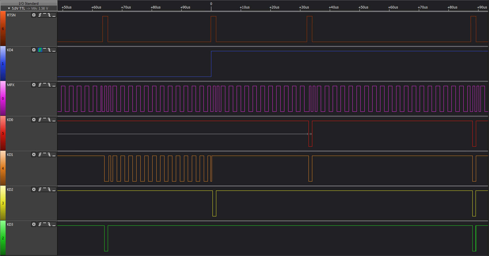
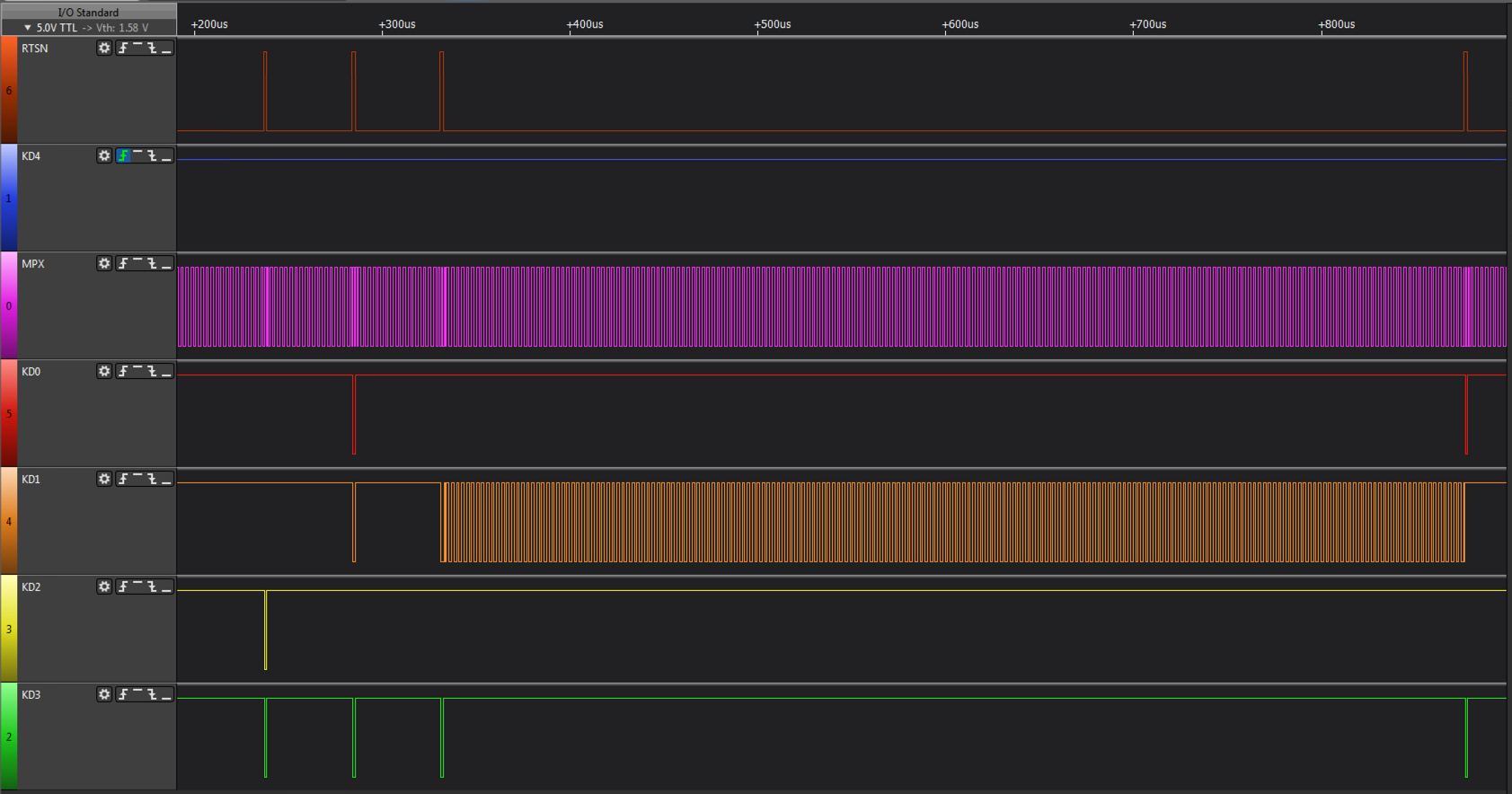
The signals can be visualised by the following logic analyzer diagrams below:
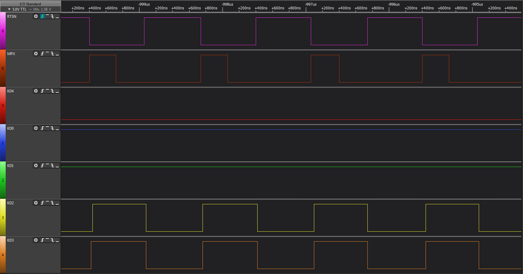
During inactivity, the gatearray on the mainboard sends a STROBEALL command, this is recognised by KD4 being LOW, the ROW, which is sent, isnt taken into consideration as the data returned is the logical AND of all keys in a given column across all rows.
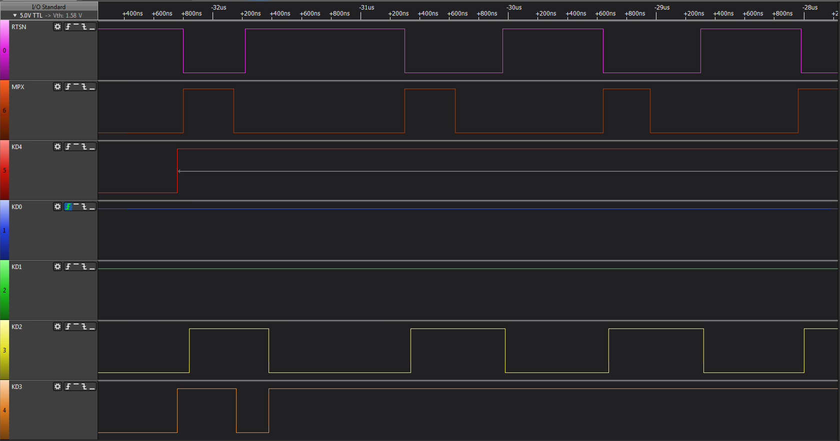
When a key is pressed, detected by the STROBEALL, KD4 goes high and the mainboard starts probing the keyboard to determine which key was pressed. It starts by sending a request to return column data for Row 11, this row contains the special keys, CTRL, SHIFT, LOCK, KANA, GRAPH.
Scan of Row 11 takes place for around 30us, I believe this is to cater for switch bounce.
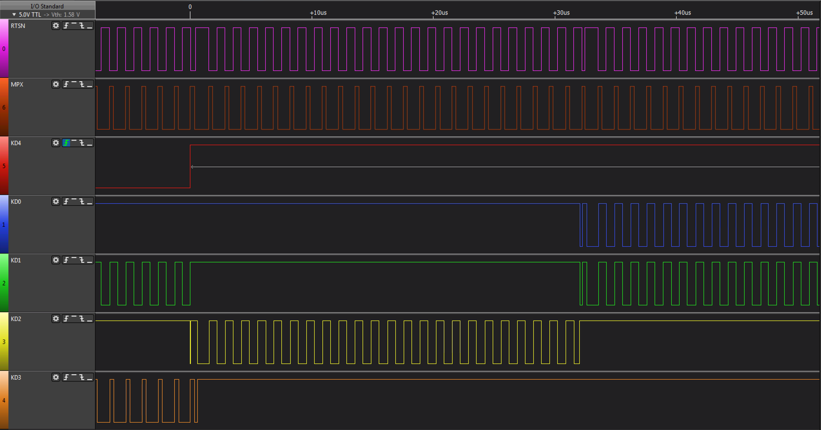
After probe of Row 11 it switches to Row 12 which contains the Japanese Transform keys. This can be seen on the left of the image, the wide RTSN pulse, look at the KD[3:0] values below and it will read 12 in binary. Row 12 is then scanned for around 50us.
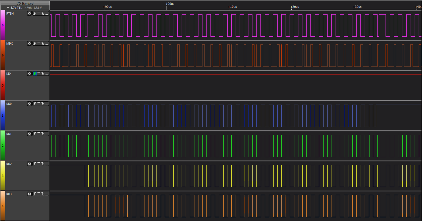
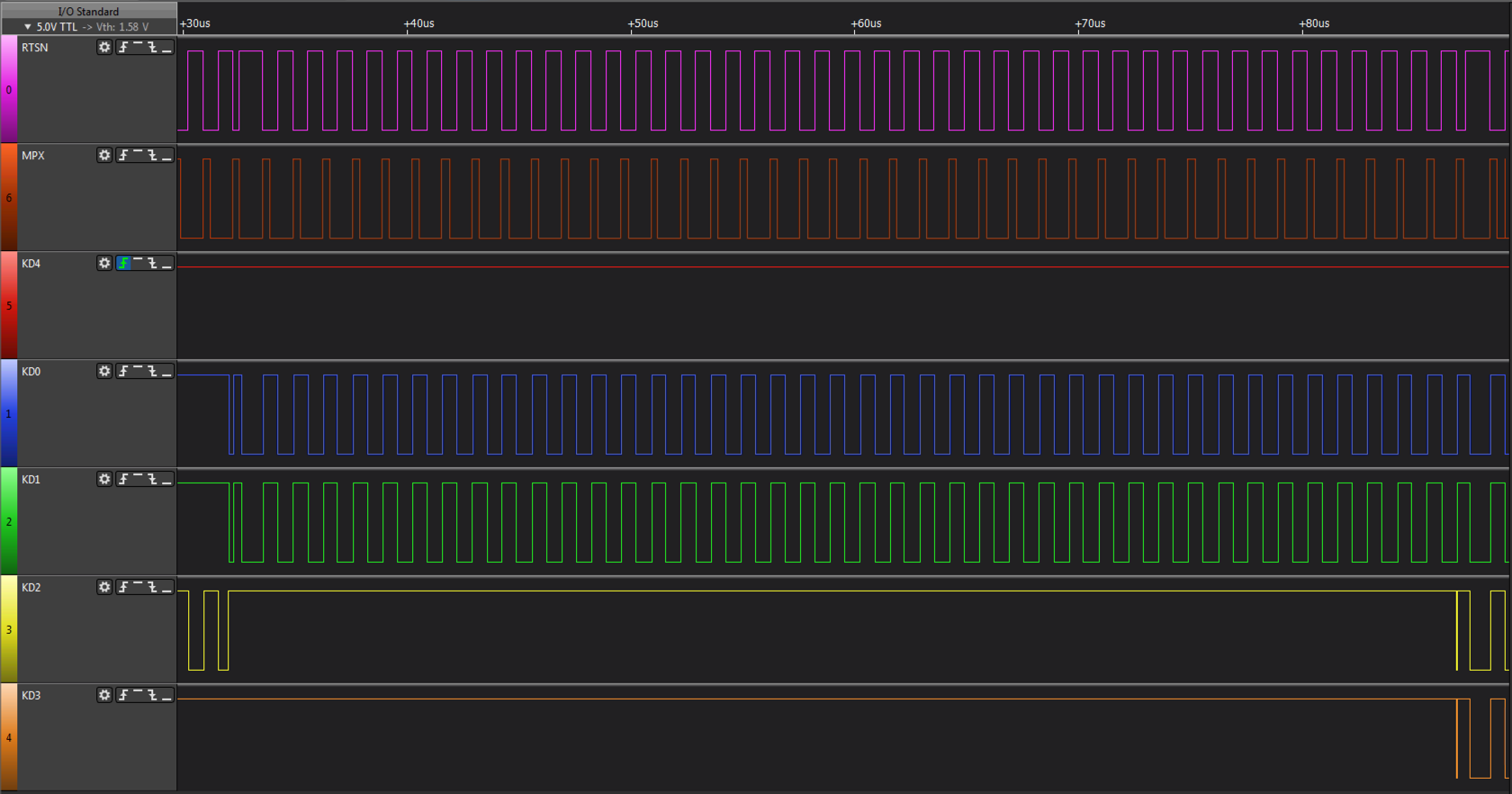
Once row 11 and 12 have been probed, the mainboard commences a sequential scan of all the rows, starting at row 0, looking for the pressed key. Again look at the wide RTSN signal pulse and you will notice KD[3:0] incrementing.
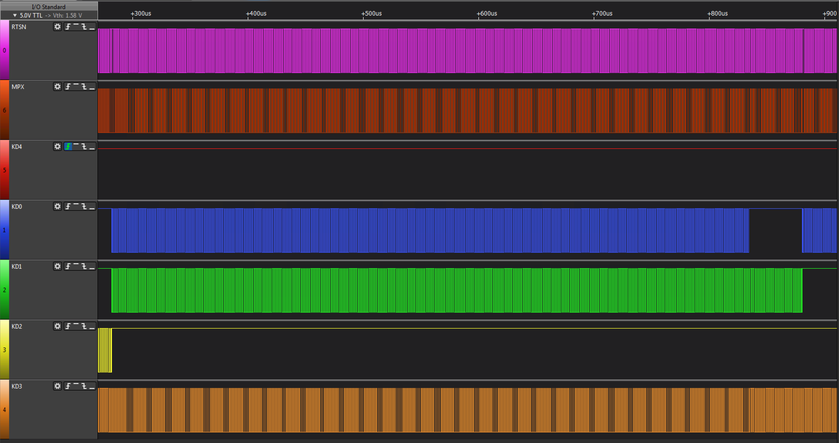
The sequential scan continues until it locates the pressed key, which in this case is
C on Row 4 Column 3. The row is scanned for more than 600us to determine key bounce. The sequential scan of the remaining rows then continues and then it repeats from row 0 until the key is released.
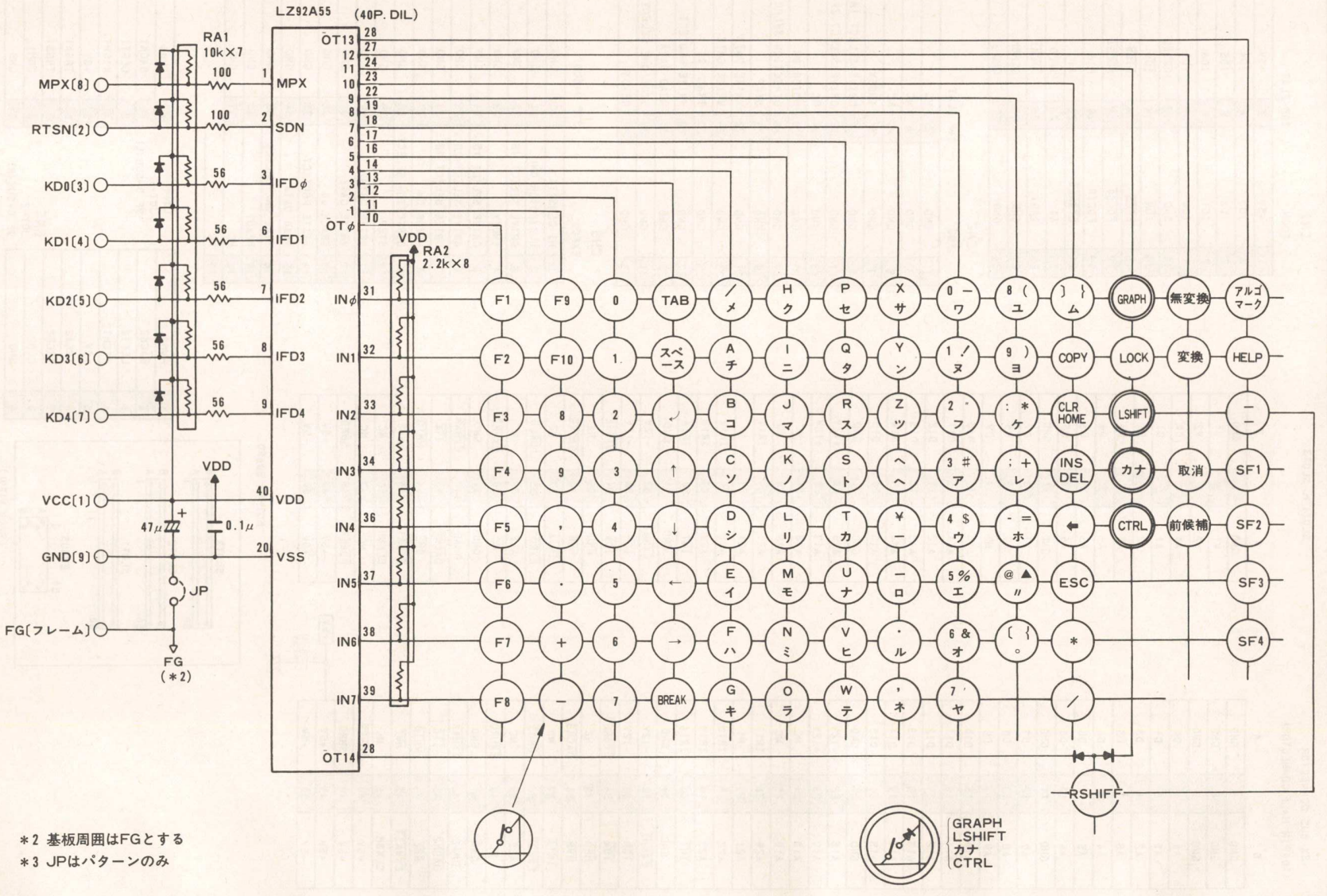
The hardware used by the MZ-2500 can be seen in the following two circuits.
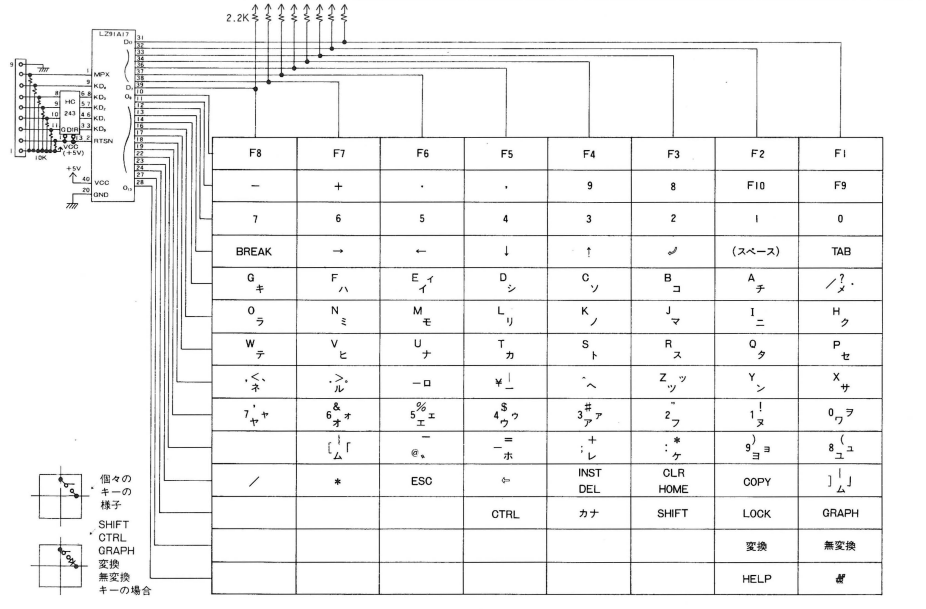
This schematic represents the keyboard circuitry which is composed of a gate array (or custom MCU, the part number doesnt reveal the type of device) and a bi-directional buffer. The gate array receives the row from the main unit and applies it to
the keyboard strobe outputs. The key data is then read and returned under control of the MPX signal.
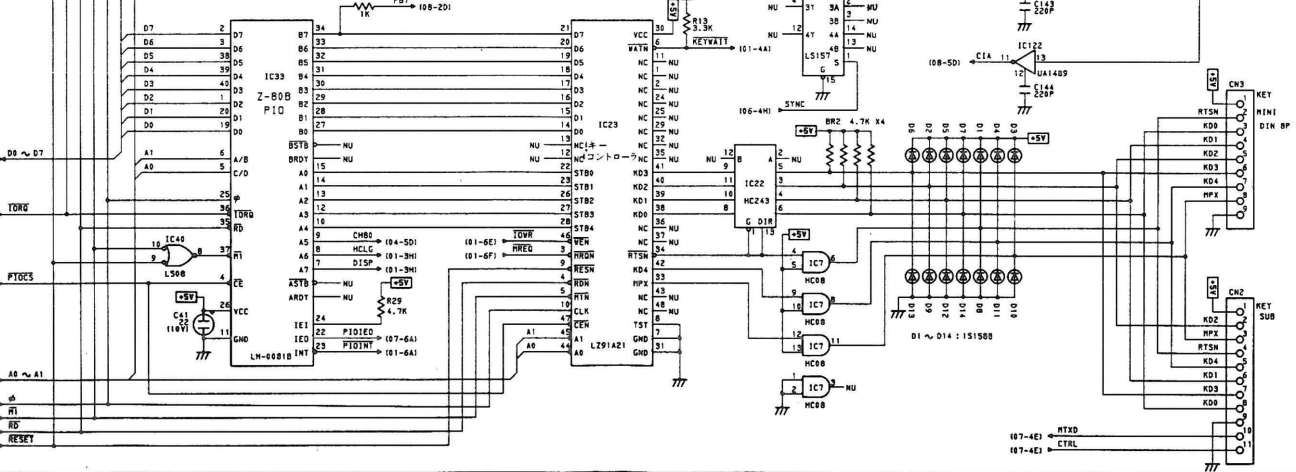
This schematic represents the main unit circuitry which comprises a gate array connected to the Z-80B PIO, which like the MZ-2000/80B expects to output a strobe row and read back an 8 bit value. The gate array appears to buffer the keyboard matrix internally
so that Z80B PIO requests are acted on immediately. In order to do this, the gate array sends out a row number, 0 .. 13 and receives 8bit block of data, in 2 nibbles from the keyboard. It does this continuously, regardless of what the main computer is doing.
MZ-2800 Keyboard Protocol
The MZ-2800 is the successor to the MZ-2500 and its design incorporates an 8 bit Z80 based MZ-2500 mode and a 16bit 80286 mode which can run MS-DOS and other 16bit 80x86 based programs. Like the MZ-2500, the keyboard hardware
interface comprises of 7 signals, 5V and GND but uses an obsolete AMP 9 pin USB style connector in a D-Sub housing. I have searched high and low for this connector or specifications on it but cannot find anything useful.
On the MZ-2800 motherboard is a standard low profile board to board 9 pin header which has the signals below, this is fed to a daughter board on which the AMP socket is mounted and then screwed to the outside casing. As I dont believe in hacking vintage equipment I searched for an alternative
and found one which uses a D-Sub with the same dimensions as the AMP connector so will afix onto the casing panel and will be a drop in replacement for the existing AMP connector. This solution means that should you ever be lucky enough to buy a real MZ-2800 keyboard, you can revert very quickly to the original AMP connector.
A recap of the signals are in the table below. They are identical physically to the MZ-2500.
RTSN, KD4, MPX are output signals from the main unit side. KD [3:0] is a bidirectional bus between the main unit and the keyboard, direction under main unit control using RTSN.
| Signal |
Direction |
Logic State |
Description |
RTSN
Row Strobe |
Main Unit -> Keyboard |
HIGH (1) |
A Row address is being transmitted from the main unit to the keyboard. |
| |
|
LOW (0) |
The keyboard is transmitting requested data over the 4 bit bidirectional bus KD[3:0]. |
KD4
Type Strobe |
Main Unit -> Keyboard |
HIGH (1) |
The keyboard must return the actual key matrix data as referenced by the Row number. |
| |
|
LOW (0) |
The keyboard must return a logical AND of all the keys, ie. D0 = AND of bit 0 on ROWS 0 to 13, D1 = AND of bit 1 on ROWS 0 to 13 etc. |
MPX
Nibble MUX Strobe |
Main Unit -> Keyboard |
HIGH (1) |
The upper nibble of the requested ROW (or AND of row data as directed by KD4) is sent from the keyboard to the main unit. |
| |
|
LOW (0) |
The lower nibble of the requested ROW (or AND of row data as directed by KD4) is sent from the keyboard to the main unit. |
KD[3:0]
Bi-dir bus |
Main Unit -> Keyboard |
|
Active when RTSN = HIGH (1), transmits the 4 bit row number of the row data from the keyboard matrix. |
| |
Keyboard -> Main Unit |
|
Active when RTSN = LOW (0), transmits 4 bits of the 8 bit column data of the requested row. 4 bits is selected by KD4 & MPX. |
The protocol for the MZ-2800, although sharing the same physical signals as the MZ-2500, is a bit different, primarily timing. The same basic principles apply, ie. RTSN goes HIGH then a row number is sent to the keyboard, RTSN goes LOW then keyboard STROBEALL or data is returned. The essential difference is timing
and the way the protocol is used to probe keys.
- RTSN goes active HIGH, the mainboard sends a scan row to the keyboard.
- Wait at least 200ns after RTSN goes active before sampling KD4 - KD4 trails RTSN
- Wait at least 650ns after RTSN goes active before reading ROW - KD[3:0] significantly trails RTSN.
- The scan row is read from KD[3:0]. In STROBEALL mode, as per the MZ-2500, the row repeats ad-infinitum with a constant value of 4 and doesnt appear to be used.
- KD4 is sampled, when LOW the logical AND of all keys per column is set for retrieval, when HIGH the actual column of the selected row is set for retrieval.
- Wait for RTSN to go inactive LOW.
- When MPX = HIGH the upper nibble of the data set for retrieval is output by the keyboard on KD[3:0] and read by the mainboard. When MPX = LOW the lower
nibble of the data set for retrieval is output on KD[3:0]. MPX has the same period as the MZ-2500, ie. 640ns, 320ns active HIGH and 320ns LOW.
- The above repeats, the row sent can vary or remain static, for example if reading the same key to determine bounce or repeat.
The primary protocol in both STROBEALL and key data retrieval modes is the same:
STROBEALL mode, the mainboard is waiting for a key to be pressed so it holds KD4 LOW. The row sent in this diagram is row 0 but it has no obvious purpose as STROBEALL mode logically AND's all rows for a given column together.
Once a key has been pressed, the mode changes to key retrieval mode. KD4 goes HIGH and the mainboard starts sending valid row numbers to retrieve column data. As per the MZ-2500, row 11 is interrogated first followed by row 12 and then a sequential sweep from row 0 occurs.
The timing delay between RTSN going active and row data being available can be seen in this diagram. Unfortunately I seem to have mislaid the timing diagram showing KD4 trailing RTSN, next time I rig up the logic analyser I will snapshot it.
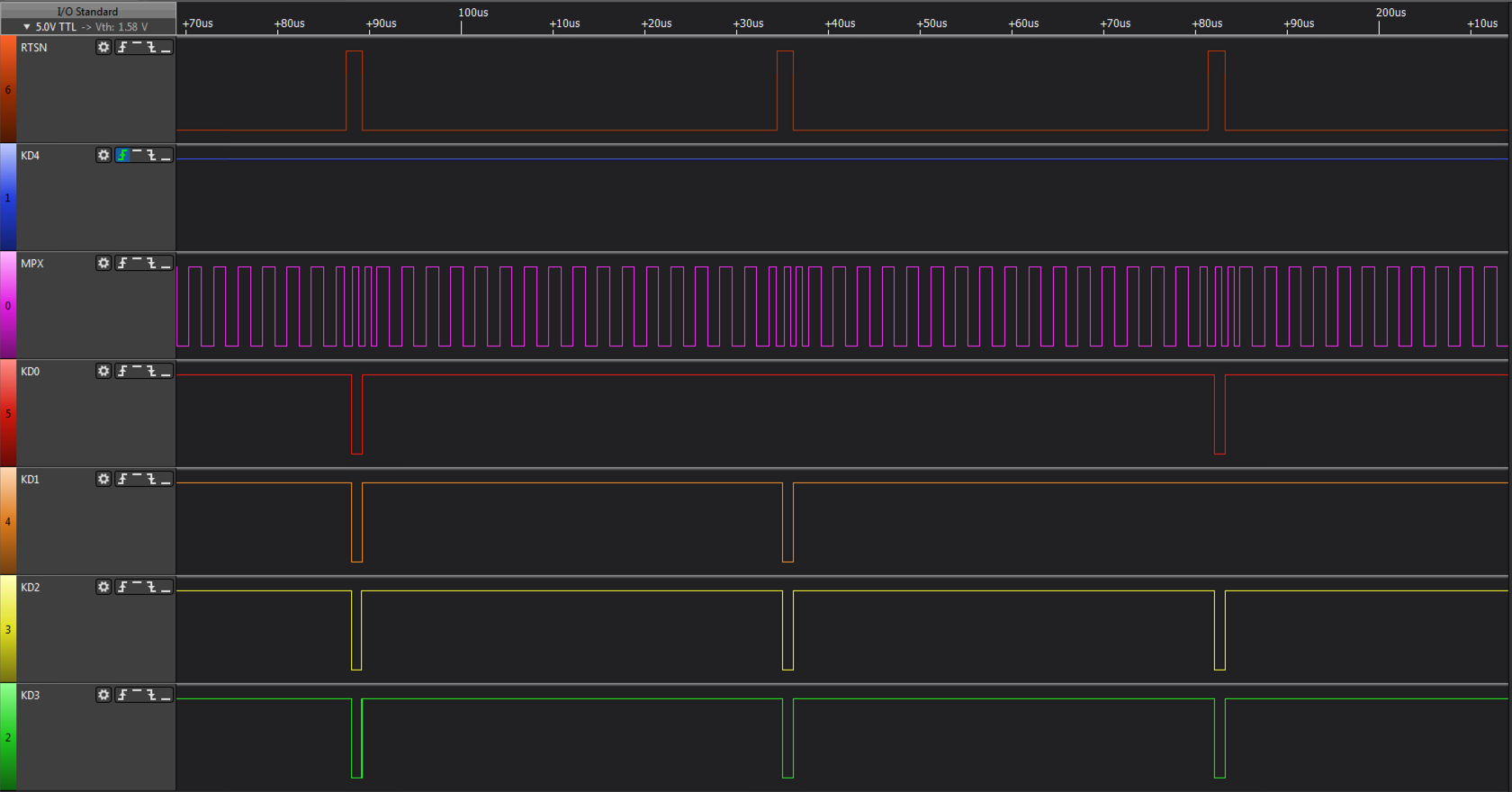
The sequential scan can be seen in the image above.
The sequential scan can be seen here. When the scan reaches the row of the pressed key (C - row 4 column 3) the same row is read for 100us to cater for debounce before the scan continues.
The sequential scan repeats whilst a key is being held down. When the scan arrives at the pressed key a second time it sans for over 300us before proceeding (NB. Key A pressed in example above).
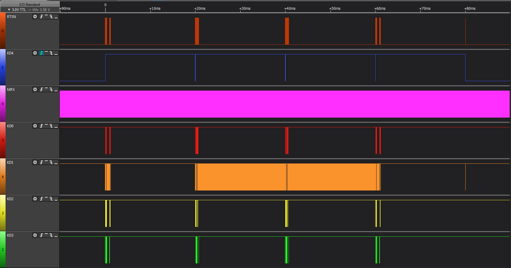
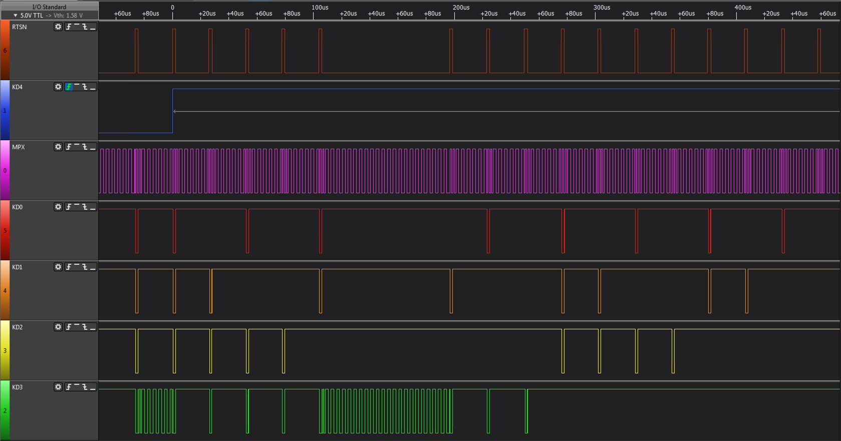
A full cycle, where a key press is detected until the moment it is released.
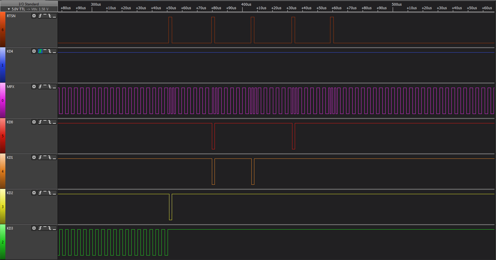
One of the differences between the MZ-2800 keyboard and the MZ-2500 keyboard is the addition of a 14th row, scan of which can be seen above. On the MZ-2800 in MZ-2500 mode, row 14 isnt scanned, it is only scanned when in MZ-2800 mode.
The hardware used by the MZ-2800 can be seen in the following two circuits.
This schematic represents the keyboard circuitry which is composed of a gate array (or custom MCU, the part number doesnt reveal the type of device) and a bi-directional buffer. The gate array receives the row from the main unit and applies it to
the keyboard strobe outputs. The key data is then read and returned under control of the MPX signal.
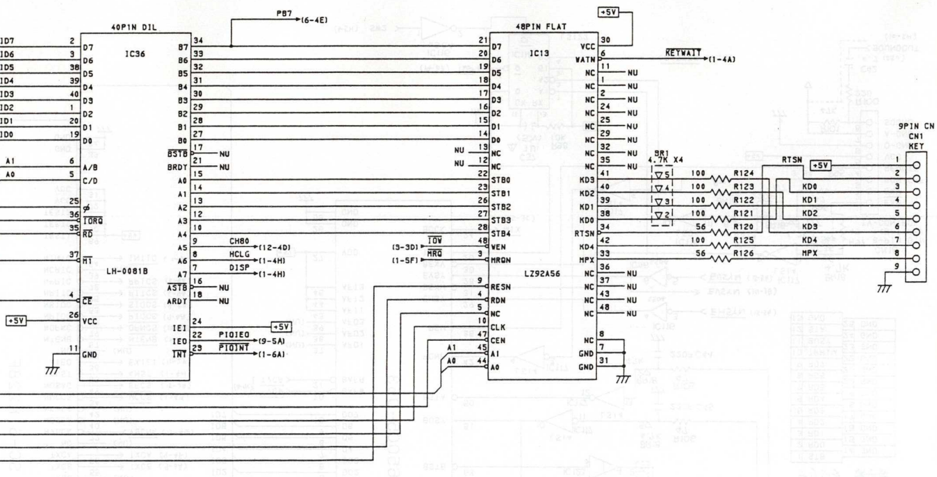
This schematic represents the main unit circuitry which comprises a gate array connected to the Z-80B PIO, which expects to output a strobe row and read back an 8 bit value. The gate array appears to buffer the keyboard matrix internally
so that Z80B PIO requests are acted on immediately. In order to do this, the gate array sends out a row number, 0 .. 14 (13 in MZ-2500 mode) and receives 8bit block of data, in 2 nibbles from the keyboard. It does this continuously, regardless of what the main computer is doing.
Sharp X1 Keyboard Protocol
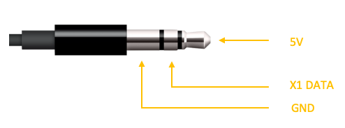
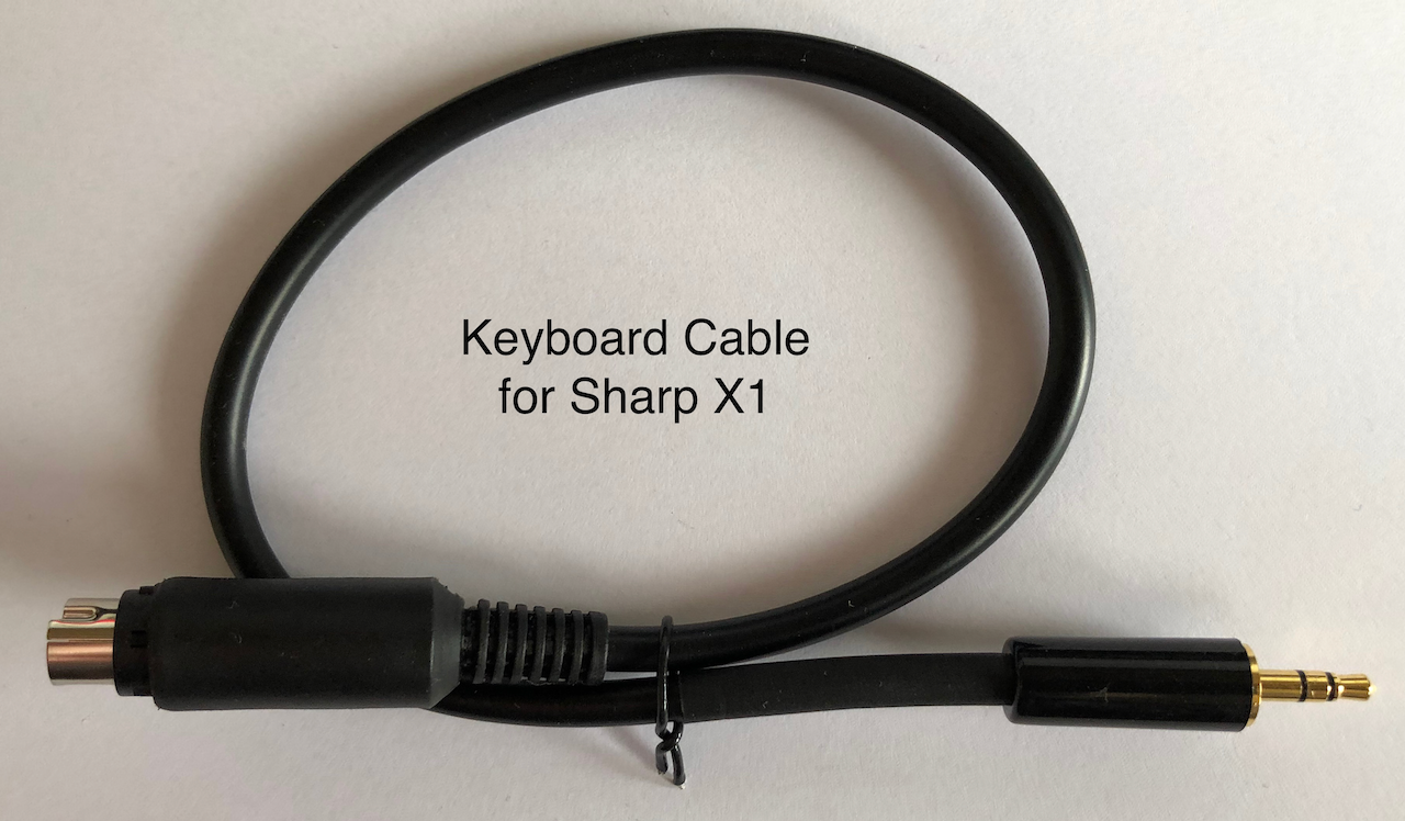
The Sharp X1 came in 3 main variants over 5 years, the X1 Original, the X1 Turbo I, II & III and the X1 TurboZ I, II & III. All the models shared the same basic keyboard technology and protocol, basically a 1 wire asynchronous 5V TTL keyboard to host signal using a 3.5mm Stereo Jack which provided
the keyboard power requirements and data transport. The 3.5mm Stereo Jack can be seen below.
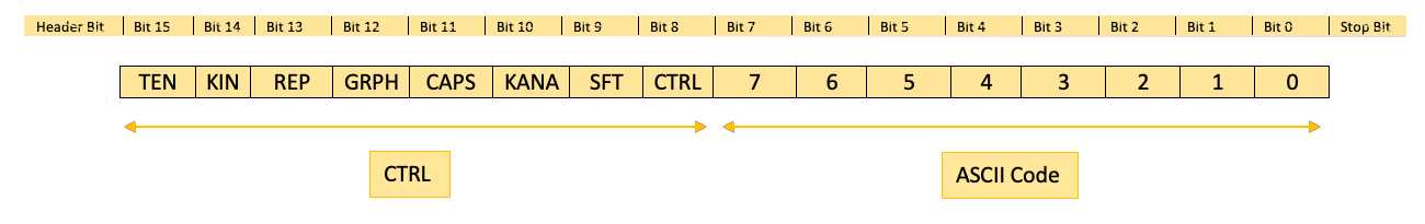
The key data is encapsulated in a start bit and stop bit with 16 data bits in-between:
| Bit |
Level |
Description |
| TEN |
High |
Normal key Input |
| Low |
Input from the numeric keypad, function keys, and special keys |
| KIN |
High |
Key Press |
| Low |
No key or key Release |
| REP |
High |
Repeat Key Input |
| Low |
First Key Input |
| GRPH |
High |
GRPH Key On |
| Low |
GRPH Key Off |
| CAPS |
High |
CAPS Key On |
| Low |
CAPS Key Off |
| KANA |
High |
KANA Key On |
| Low |
KANA Key Off |
| SFT |
High |
Shift Key On |
| Low |
Shift Key Off |
| CTRL |
High |
CTRL Key On |
| Low |
CTRL Key Off |
| 7:0 |
|
ASCII Key Code |
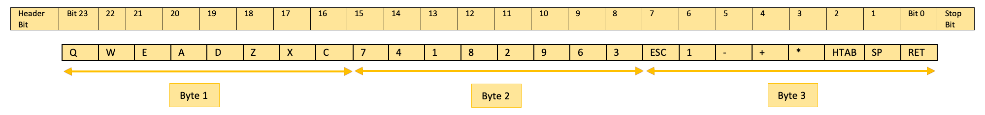
The Turbo and TurboZ models added an additional mode, referred to as Mode B (above protocol became known as Mode A), which was optimised for games and transmitted a start bit, 24 data bits and a stop bit, with the logic state pulse width being half of Mode A therefore 24bits take less
time to transmit than Mode A 16bits:
| Bit |
Level |
Description |
| Q,W,E,A,D,Z,X,C |
High |
No key pressed |
| Low |
Key pressed |
| 7,4,1,8,2,9,6,3 |
High |
No key pressed |
| Low |
Main or Keypad Key pressed |
| ESC,1,-,+,*,HTAB,SP,RET |
High |
No key pressed |
| Low |
Main or Keypad Key pressed |
The timing of each bit varies between Mode A and Mode B, with mode B optimised for gaming. The bit time periods are below:
| Mode |
Header Bit |
Data Bit Low |
Data Bit High |
Stop Bit |
| |
Low |
High |
Low |
High |
Low |
High |
Low |
High |
| Mode A |
1000uS |
700uS |
250uS |
750uS |
250uS |
1750uS |
250uS |
250uS |
| Mode B |
400uS |
200uS |
250uS |
250uS |
250uS |
750uS |
250uS |
250uS |
To understand the protocol in more depth, the following diagrams visualise data transmission in Mode A and Mode B.
 Mode A, Key A pressed.
 Mode A, Key B pressed.
 Mode A, Key C pressed.
 Mode A, KANA selected and Key A pressed.
 Mode A, SHIFT pressed along with Key A pressed.
 Mode B, Key A pressed.
 Mode B, Keypad 4 pressed (Cursor Left).
 Mode B, Keypad 6 pressed (Cursor Right).
Sharp X68000 Keyboard Protocol
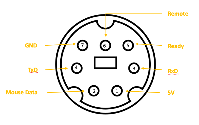
The Sharp X68000 came in 11 variants over its 6 years of manufacture, the Original, ACE, EXPERT I/II, PRO I/II, SUPER, XVI, Compact, X68030, X68030 Compact. All the models shared the same keyboard technology which was based on a start + 8bit + stop bit at 2400 Baud Asynchronous protocol at 5V TTL level. The protocol is bi-directional allowing the host to change settings
and LED states of the keyboard. The physical connection is based on a mini-DIN7 connector which includes power supply, mouse and ready state signals. The connector can be seen below:
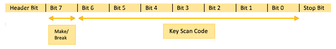
The protocol at the Data Link layer is relatively simple. The keyboard transmits a scan code for each key pressed with the MSB indicating key press (1) or release 0. In addition, the host can transmit several commands to the keyboard, of which 4 are known, relating to the keyboard LED's being lit, brightness, typematic repeat time and delay. The diagrams below
indicate each of the possible data flows:
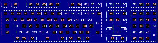
Basic keyboard to host data packet, one byte transmitted per key press/release. Key press MSB = 1, key release MSB = 0.
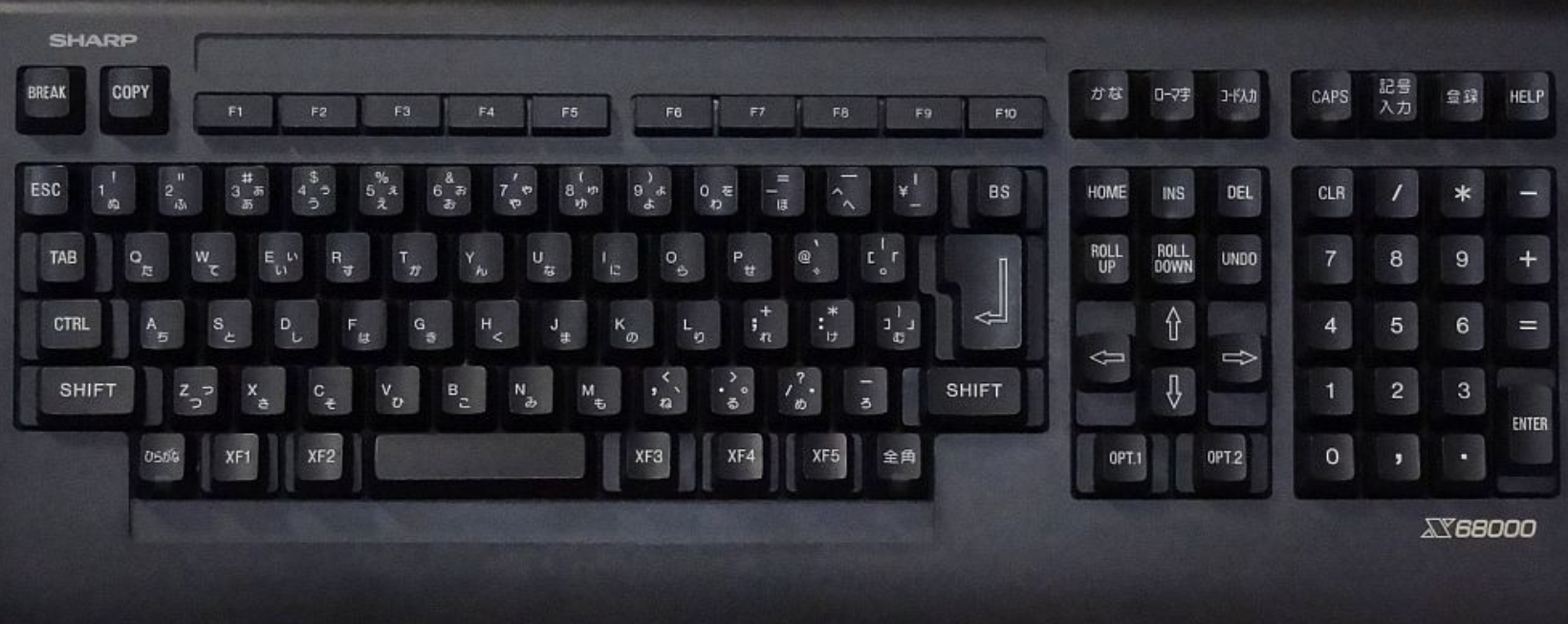
The scancodes returned for each key pressed can be seen in the layout above.
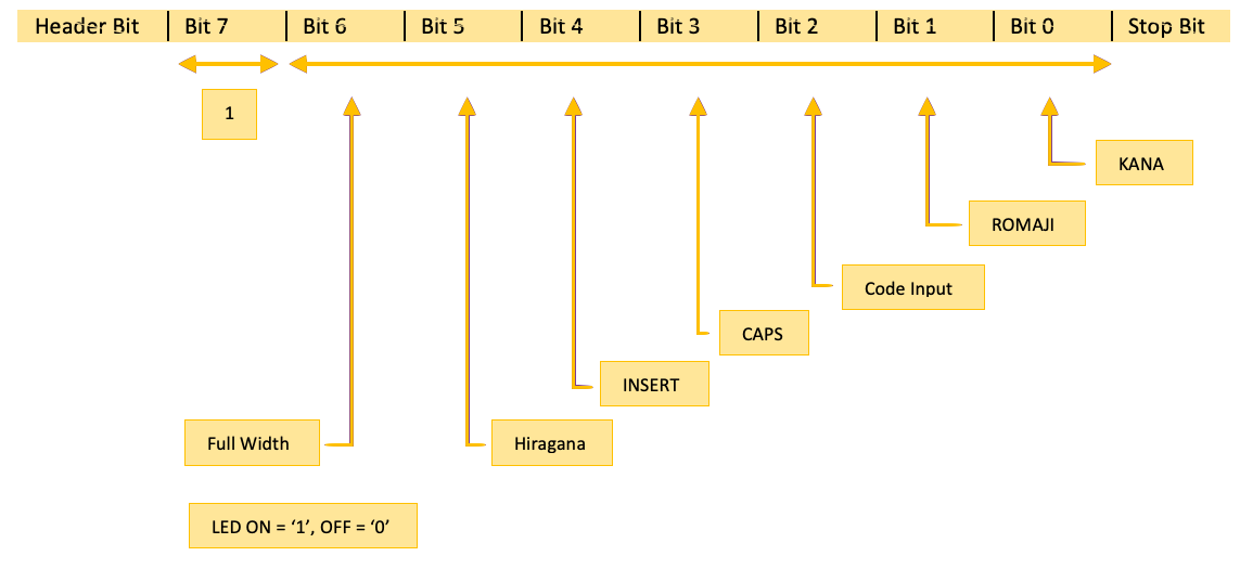
Command sent by the host to the keyboard to illuminate or extinguish LED’s.
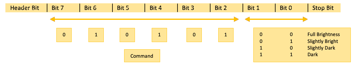
Command sent by the host to the keyboard to set the brightness of illuminated LED’s.
Command sent by the host to the keyboard to set the key repeat delay time.
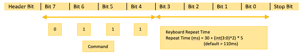
Command sent by the host to the keyboard to set the key repeat time period, ie. key release to next key press whilst the same key is held.
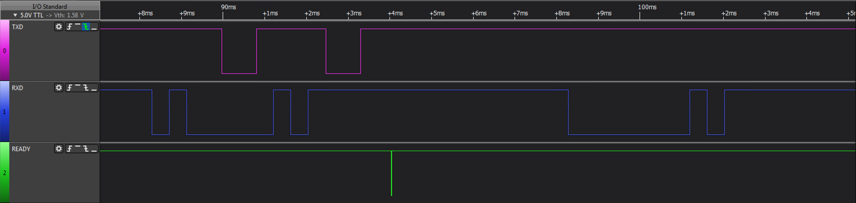
To understand the protocol in more depth, the following diagrams visualise data transmission at the physical layer:
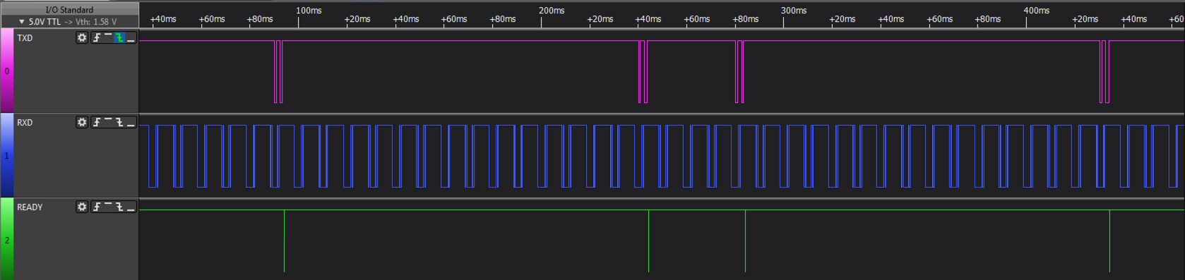
Basic key transmission between the Keyboard and Host, TxD represents data flowing from the keyboard to the host, RxD represents data flowing from the host to the keyboard, READY represents the host
ready to accept new data when high, busy when low. The host is continually transmitting to the keyboard, the leading bits in a packet determine the command. The keyboard transmits on key press, key repeat and key release.
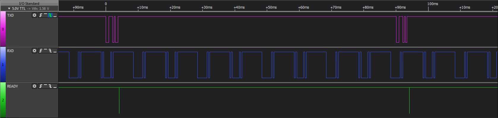
Up close, the keyboard transmitting key A press (scancode 0x1E) to the host.
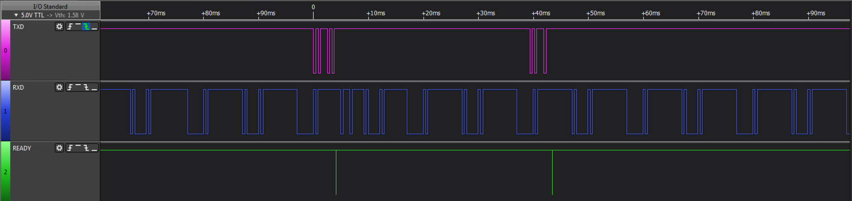
Keyboard transmitting key B press (scancode 0x2E) and release.
Keyboard transmitting CAPS lock press (scancode 0x5E) and the host transmitting set LED CAPS command to the keyboard.
Sharp Mouse Protocol
When thinking of the Sharp Mouse, the X68000 comes to mind with its SX Windows system and mouse enabled applications. In fact the same mouse technology was used on earlier machines such as the Sharp X1, MZ-2500 and MZ-2800. It is very similar to the PS/2 Mouse protocol
just not as configurable and lower resolution.
The protocol is based on an asynchronous serial protocol over two wires (MSDATA/MSCTRL). The MSCTRL signal is an enable signal, idle state = HIGH, it goes low prior to transmission of data by at least 1mS and goes high after
transmission of last bit by ~2.56mS.
The MSDATA signal is a standard asynchronous serial signal, idle = HIGH, 1 start bit, 8 data bits, 2 stop bits @ 4800baud.
The Idle state of both MSDATA and MSCTRL is High.
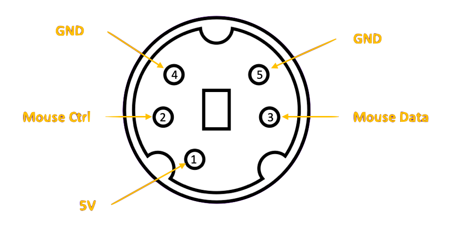
The connector pinout can be seen below, plug view:
The Physical layer of the transmission protocol from Mouse to Host is:
- HOST sets MSCTRL -> LOW
- 1ms delay
- Mouse sets MSDATA -> low, first start bit.
- 3 bytes transmitted in a <1 x Start bit><8 x data bits><2 x stop bits> format.
- Mouse sets MSDATA -> high
- 2.56ms delay.
- HOST sets MSCTRL -> HIGH
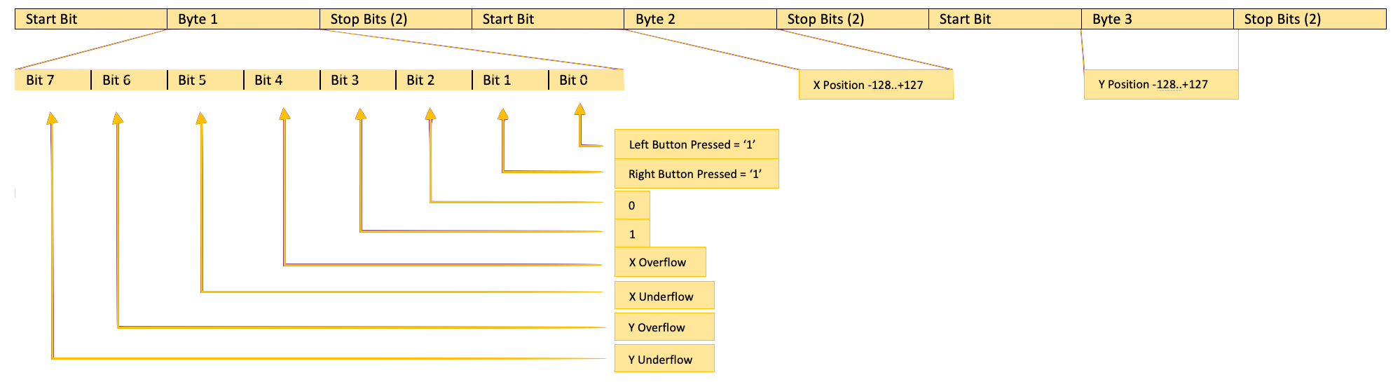
The Data Link layer of the Mouse protocol encapsulates 3 bytes transmitted every 20ms, regardless of data change, is as follows:
The X/Y resolution is -128..+127 on both planes. If the minima of -128 is exceeded, the Underflow bit of the associated plane (X/Y) is set. If the maximum +127 is exceeded,
the Overflow bit of the associated plane is set. Data (3 bytes) is transmitted from the Mouse to the Host every 20ms regardless of wether there has been movement or key press.
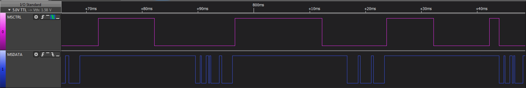
To understand the protocol in more depth, the following diagrams visualise data transmission at the physical layer:
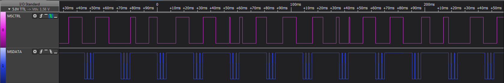
Idle state, no data is being sent other than empty packets. It is important a packet is sent every 20ms to the host.
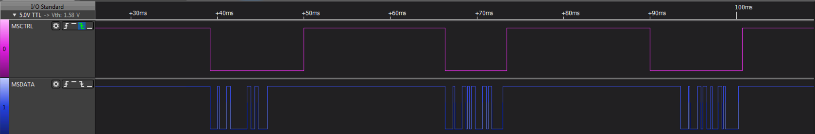
The mouse is tracking and movement data generated.
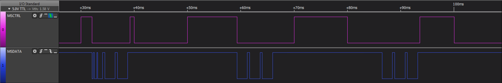
The mouse is stationary with the Left Key pressed.
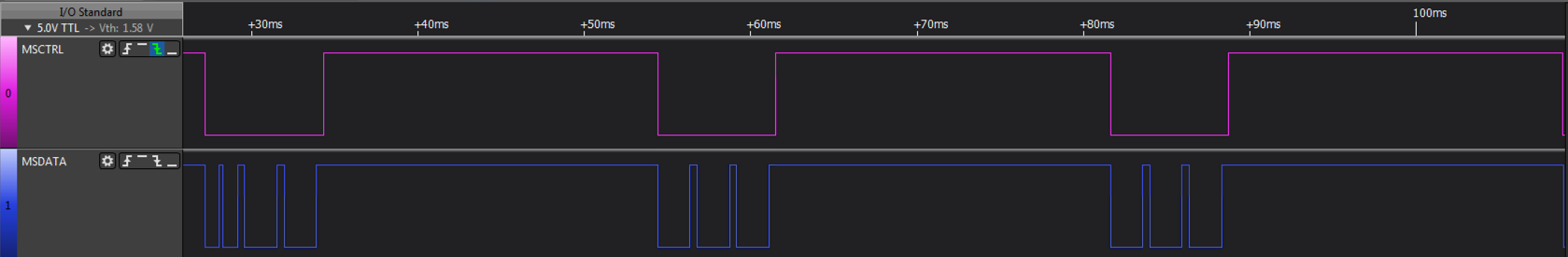
The mouse is stationary with the Right Key pressed.
The mouse is stationary with the Middle Key pressed.
ESP-32S AI Thinker
The ESP-32S is a system-on-a-chip microprocessor unit from a Shanghai based company, Espressif. The unit uses the Tensilica Xtensa LX6 Dual Core processor enriching it with an abundance of
I/O and memory including WiFi and Bluetooth units. The SoC is sold as a QFP/QNP unit without flash RAM or in most cases, a preassembled and WiFi shielded module from companies such as Espressif and
AI Thinker in various configurations and formats.
The SharpKey uses the ESP-32S-WROOM modules and some of its capabilities can be seen below:
- Processor:
- CPU: Xtensa dual-core 32-bit LX6 microprocessor, operating at 240 MHz and performing at 600 DMIPS
- Ultra low power (ULP) co-processor
- Memory: 320 KiB RAM, 448 KiB ROM
- Wireless connectivity:
- Wi-Fi: b/g/n
- Bluetooth: v4.2 BR/EDR and BLE (shares the radio with Wi-Fi)
- Peripheral interfaces:
- 34 × programmable GPIOs
- 12-bit SAR ADC up to 18 channels
- 2 × 8-bit DACs
- 10 × touch sensors (capacitive sensing GPIOs)
- 4 × SPI
- 2 × I²S interfaces
- 2 ×I²C interfaces
- 3 × UART
- SD/SDIO/CE-ATA/MMC/eMMC host controller
- SDIO/SPI slave controller
- Ethernet MAC interface with dedicated DMA and planned IEEE 1588 Precision Time Protocol support
- CAN bus 2.0
- Infrared remote controller (TX/RX, up to 8 channels)
- Motor PWM
- LED PWM (up to 16 channels)
- Hall effect sensor
- Ultra low power analog pre-amplifier
- Security:
- IEEE 802.11 standard security features all supported, including WPA, WPA2, WPA3 (depending on version) and WLAN Authentication and Privacy Infrastructure (WAPI)
- Secure boot
- Flash encryption
- 1024-bit OTP, up to 768-bit for customers
- Cryptographic hardware acceleration: AES, SHA-2, RSA, elliptic curve cryptography (ECC), random number generator (RNG)
- Power management:
- Internal low-dropout regulator
- Individual power domain for RTC
- 5 μA deep sleep current
- Wake up from GPIO interrupt, timer, ADC measurements, capacitive touch sensor interrupt
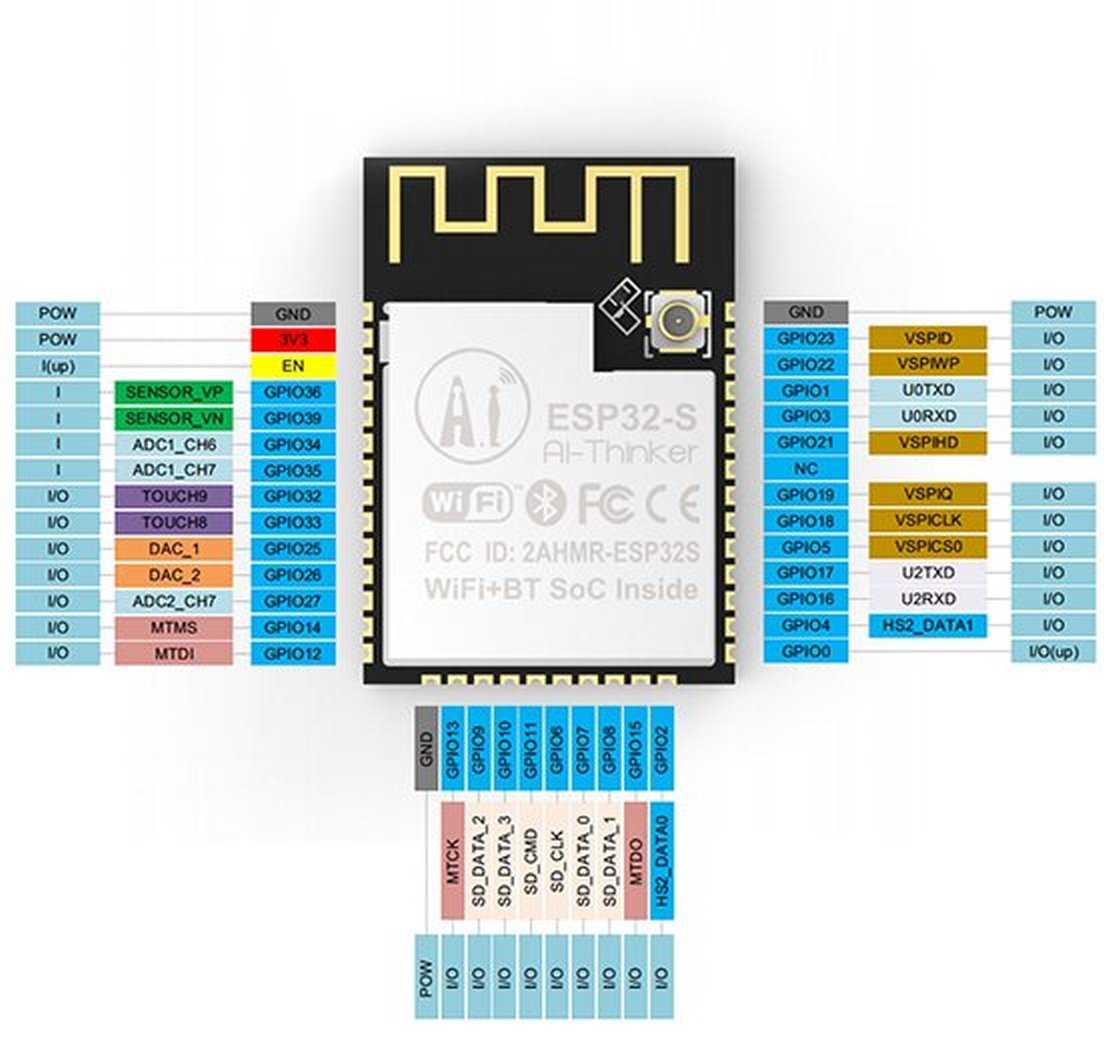
The SoC WROOM module pinout can be seen below, note the abundance of GPIO's available, small form and embedded WiFi antenna.
On first read of the specifications, it is an impressive SoC, low cost, abundance of memory and 32bit dual core power, including a lot of GPIO ports but wth a caveat-emptor insomuch therein lies many
gotchas.
Many of the I/O's are overloaded, some you will find in the hardware documentation are unuseable by third party designs but others you only really appreciate this when writing
the firmware.
For example, looking at the hardware specification you notice that you have GPIO 6, 7, 8, 9, 10, 11 fanning out and available from the WROOM module but dig deeper and you find these are unuseable as they are dedicated to the boot device Flash RAM/ROM. True, you could add additional SPI devices onto these ports
but you need to be aware that they are not otherwise useable.
Another example is GPIO2, if not held low will prevent the chip from booting, thus relegating the GPIO port to purely output mode unless you can guarantee startup state is
0 or add discriminator logic based on boot state, same for GPIO12 which must be held low etc. Again, true for many other devices including Cyclone FPGA's I'm familiar with but it takes some digging
in the documents to find this and reduces the number of available GPIO's.
Other
gotchas you find out when writing the firmware, for example, ports ADC2 dont operate well in analogue mode when WiFi is enabled and in fact, pulsing high frequency digital signals onto these pins when configured in digital
mode will prevent the WiFi Client mode from startup.
In summary, an impressive chip, great eco system, low unit cost but a lot of learning on shortcomings due to feature overloading on GPIO pins.
The ESP-32S WROOM module was chosen for the SharpKey design based on its size, features and power (and that I had some evaluation samples). The information available for the ESP-32 both in hardware and software is very impressive and helped expedite the design (excepting the issues mentioned above, but once understood
the eco system is very beneficial. It took me less than a month, including analysis of the Sharp protocols, PCB design, fabrication and firmware to create the
mz25key using this SoC and its eco system and a further 2 weeks to add the MZ-2800 capabilities, so a RAPID development cycle given
Espressif's underlying support.
Schematic
The SharpKey is basically an mz25key with a changeable host cable and extra signals coupled to the ESP-32S SoC. After designing the mz25key it became apparent, primarily as I had many Sharp machines without interfaces, that having one design for all machines would be beneficial. The mz25key was a working
design and with a few modifications, mainly at the PCB level, I could enhance it to fulfil the new requirement. The circuit below was the outcome, SharpKey v1.3a (mz25key v1.2 ++).
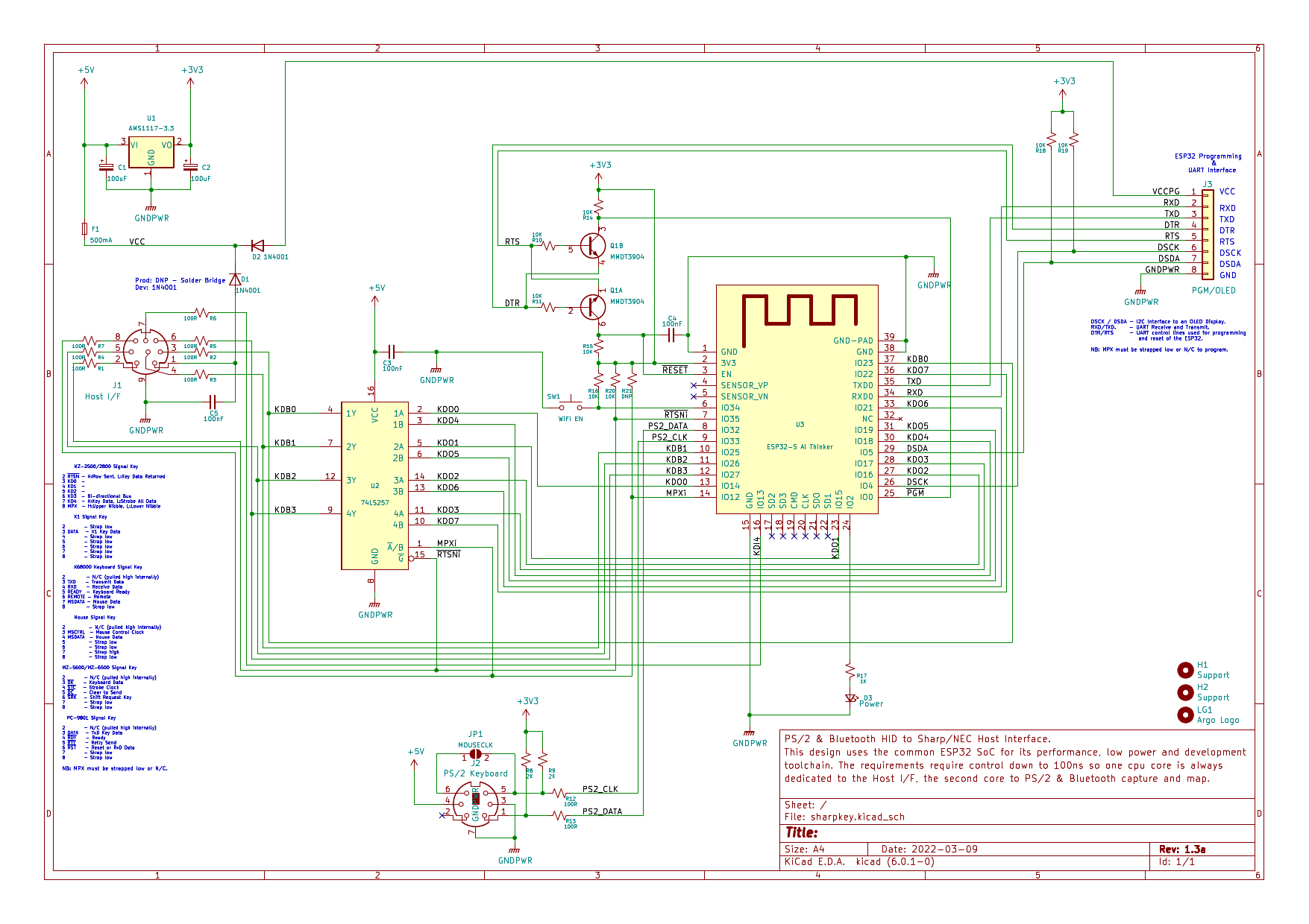
As per the section above, the design is based around the ESP-32S WROOM which is a dual core 240MHz WiFi/BT enabled SoC requiring minimal support components to operate.
The device is 5V tolerant but operates at 3.3V, so the obvious choice for the PSU, having used them for the tranZPUter and have plenty in stock, is
the AMS1117 3.3v converter. It is relatively efficient, only dropping 1.1v at approx 30mA (150mA if the WiFi mode is enabled) and supplies a stabilised low ripple output. Under normal conditions the device is powered by the host keyboard or mouse port but on occasion it will need
to be connected to a programming interface. In order to avoid mistakes, connecting the host port and programming interface simultaneously, rectifier diodes are used to isolate the two power sources (production boards only have the programming diode installed as testing has show a number of older machines
do not provide 5V at the keyboard/mouse port and the 0.6V drop of a diode can affect the ESP32 brownout circuit). A fuse is also used to protect the host port should something go faulty or a short occur during development and probing.
The programming interface is very simplistic (no convoluted ARM Cortex programming here), two serial wires from a 3.3/5V UART. In order to work seamlessly with the Espressif IDF build and programming system, an automated bootstrap circuit (Q1A/B) is added and driven by RTS/DTR, this allows the build system
to place the ESP-32S into programming mode, program it and then force a reset. Makes for very easy development, CI/CD eat your heart out!!!
The PS/2 interface is a standard design used in Espressif solutions. 2 bi-directional pins driving a PS/2 keyboard/mouse with a protocol similar to I2C, specifications can be found
here. The ESP32 can sink/source sufficient current to meet the PS/2 specifications without need for additional transistors.
As the timing of the MZ-2500/MZ-2800 host interface is time critical and 2 nibbles need to be delivered 300ns apart, I thought it prudent to drive out a byte from the ESP32 into a 2-1 multiplexer under control of the MZ-2500/MZ-2800, so the timing requirements were lessened. On detection of the RTSN signal going high
the ESP32 would read in the row number, lookup the matrix value (built up from incoming PS/2 keys) and output a byte to the mux. Resistors are added on all the host side signals to limit current and reduce line reflection.
Timing of the Sharp MZ-5600, MZ-6500, X1, X68000, NEC PC-9801 and Mouse protocols are not as critical as the MZ-2500/2800 so no special additions are required to the circuit over and above those designed for the MZ-2500/2800.
A switch is installed in the design to allow enabling of the onboard WiFi transceiver and Bluetooth Pairing procedure. Under normal use the Wifi is switched off to conserve power and to prevent interference, but pressing the switch for a pre-determined amount of time (see the
User Manual)
enables Wifi or Bluetooth (enters pairing mode) transceivers.
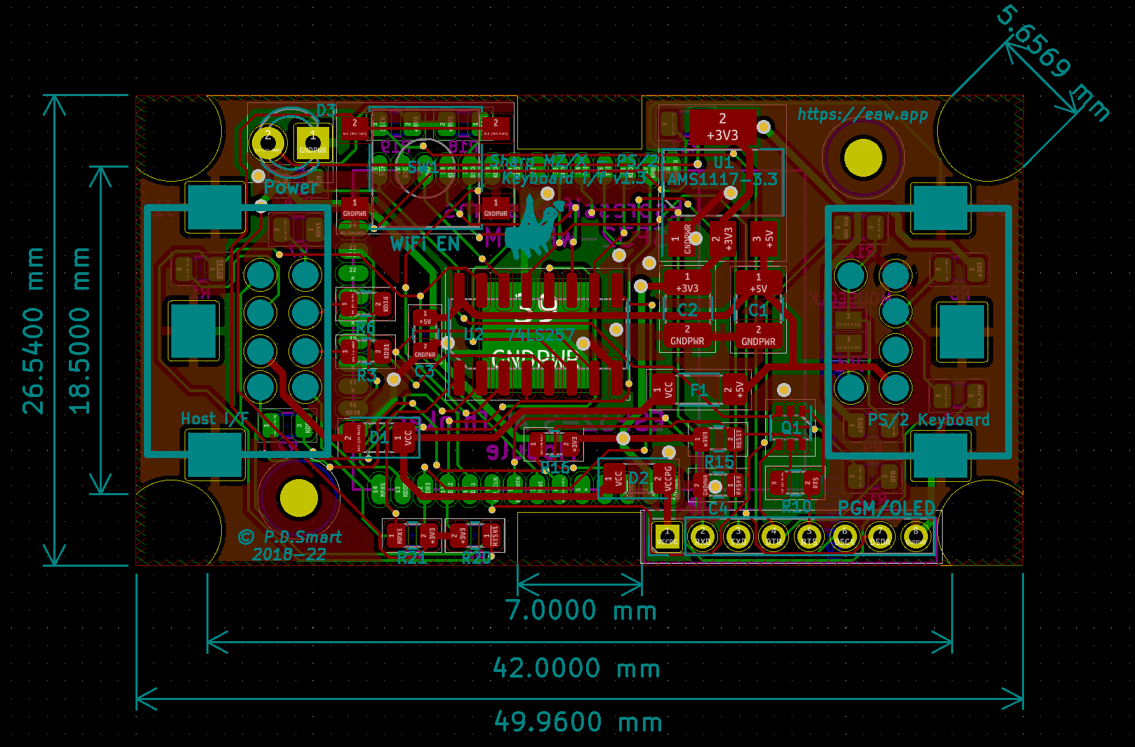
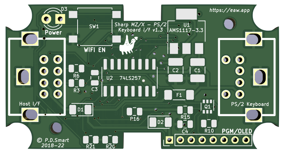
PCB
The SharpKey was based on the proven mz25key design but the PCB and layout, apart from the physical board dimensions, could not be used. The addition of a 2nd mini-din socket and additional components compacted the design and free space more limited. This led to a complete re-route and part placement.
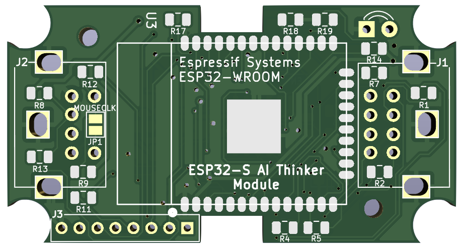
The finished fabricated production circuit board 3D model.
Bill Of Materials
Click BOM on the left side bar to see an interactive Bill Of Materials, listing all the components used in the SharpKey and their location. Use this guide to
place components when assembling a PCB or to identify components when developing.
Programming Interface
The SharpKey has an inbuilt Over The Air update facility which only requires a web browser and a file to program the latest firmware and filesystem. The firmware update features automatic rollback so should the the latest release fail to work it will rollback
automatically and restart the current firmware version. Under normal circumstances nothing more is needed.
If the device becomes corrupt, for example, the filesystem which isnt fault tolerant fails to fully update, it may be necessary to update the firmware and/or filesystem via a hard wired interface.
The SharpKey incorporates a programming header internally and this can used in such circumstances. A USB or similar 5V TTL to UART adapter is required and should be wired according to the diagram below (the OLED is optional and only required for development and debugging):
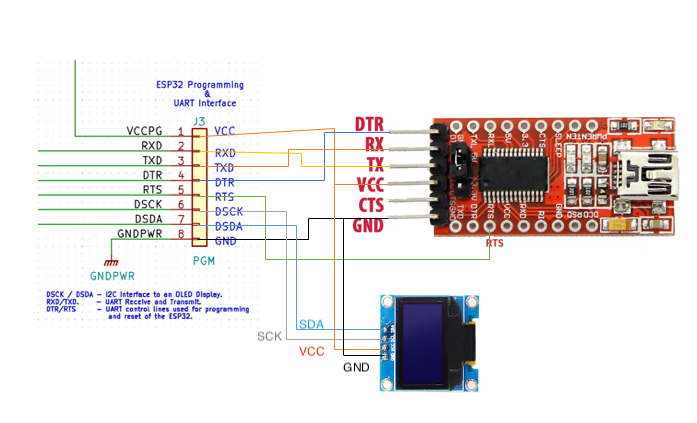
The software required for programming the device is part of the Espressif development environment, which is a free download. Please refer to the firmware guide for details on installation and use.
Host Interface Cables
The SharpKey has a unique ability to interface to many Sharp and NEC Host Computers. This is primarily down to firmware but the cable wiring is also important. Not only does the cable interface the correct input/outputs of the SharpKey to the Host Keyboard/Mouse port but its unique wiring combined with firmware probing algorithms
can detect the type of host to which the SharpKey is connected.
This section outlines the SharpKey to Host cable wiring requirements which are important to ensure correct operation.
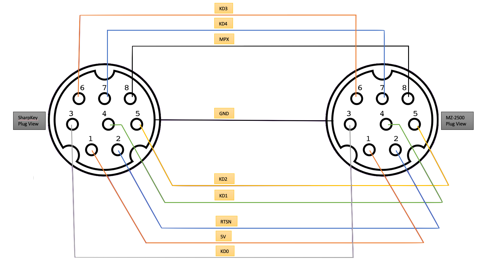
Sharp MZ-2500 Cable
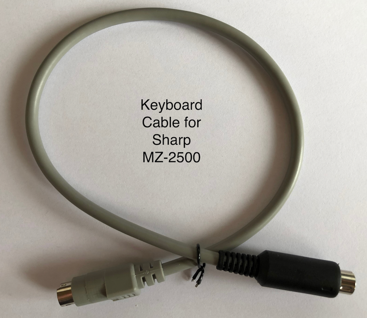
The Sharp MZ-2500 keyboard port uses a mini-DIN8 socket, the same as the SharpKey. A cable needs to be made using the diagram below between a mini-DIN8 plug on the MZ-2500 side and a mini-DIN8 plug on the SharpKey side.
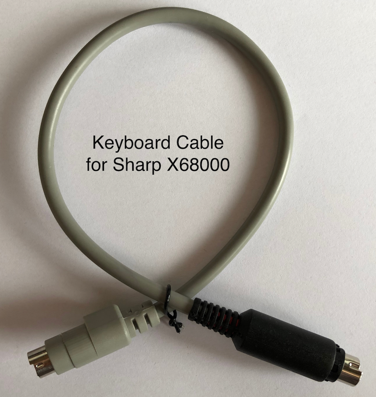
The MZ-2500 keyboard port extends into the main unit casing so you will need a thin pre-fabricated mini-DIN8 connector (ie. like the grey connector in the photo below) as the standard self assembly connectors are a bit too thick
to be used (ie. the black connector in the photo below).
The Sharp MZ-2500 Mouse port uses a mini-DIN5 socket and the section below on Sharp Mouse should be used.
Sharp MZ-2800 Cable
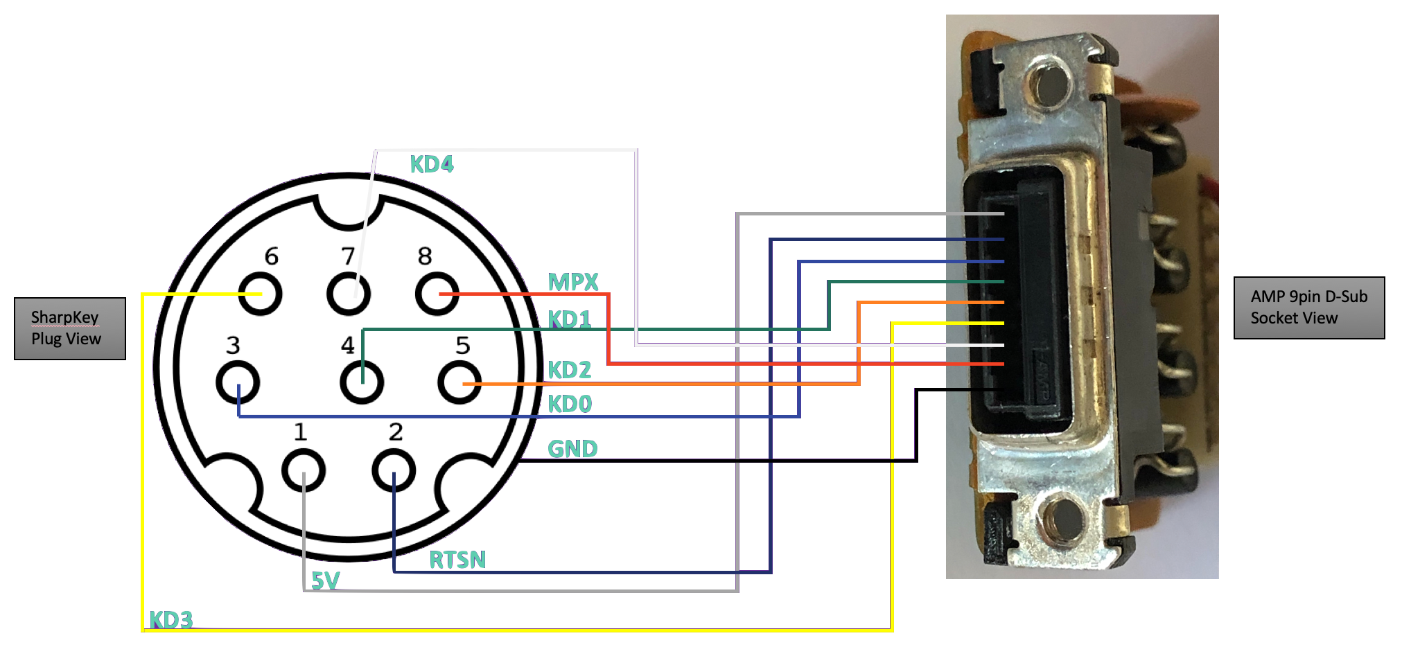
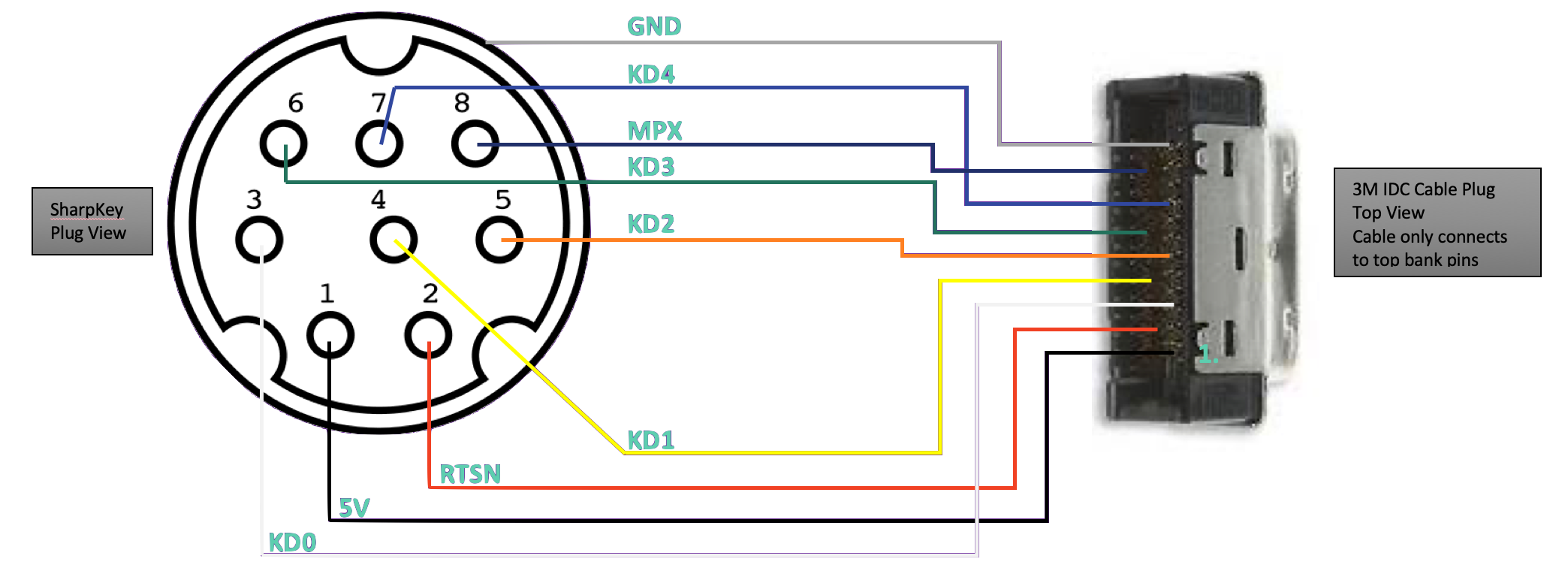
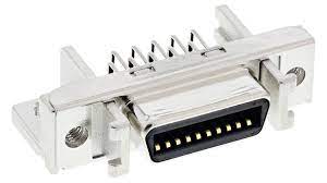
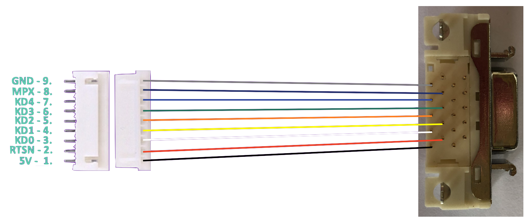
The Sharp MZ-2800 keyboard uses an AMP 9pin D-Sub connector which is no longer available. If you are lucky enough to find one then a cable needs to be made using the diagram below between a 9pin AMP D-Sub plug on the MZ-2800 side and a mini-DIN8 on the SharpKey side. Please note the diagram shows the wiring towards a socket as
no plug was available whilst making this document.
You will most likely find yourself with an MZ-2800, no keyboard and no AMP 9pin D-Sub plug. In this situation, which I'm sure will be most common unless a stash of AMP 9pin D-Sub plugs is unearthed in a warehouse and put up for sale, the solution below can be used. It will need some skills as it involves opening up the MZ-2800 and changing parts
but not so difficult.
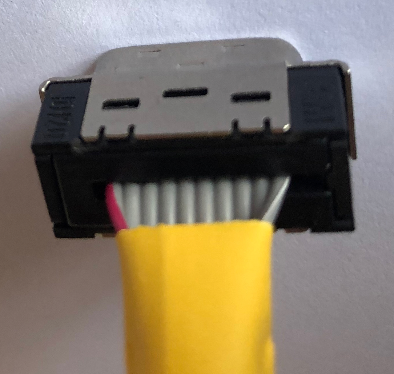
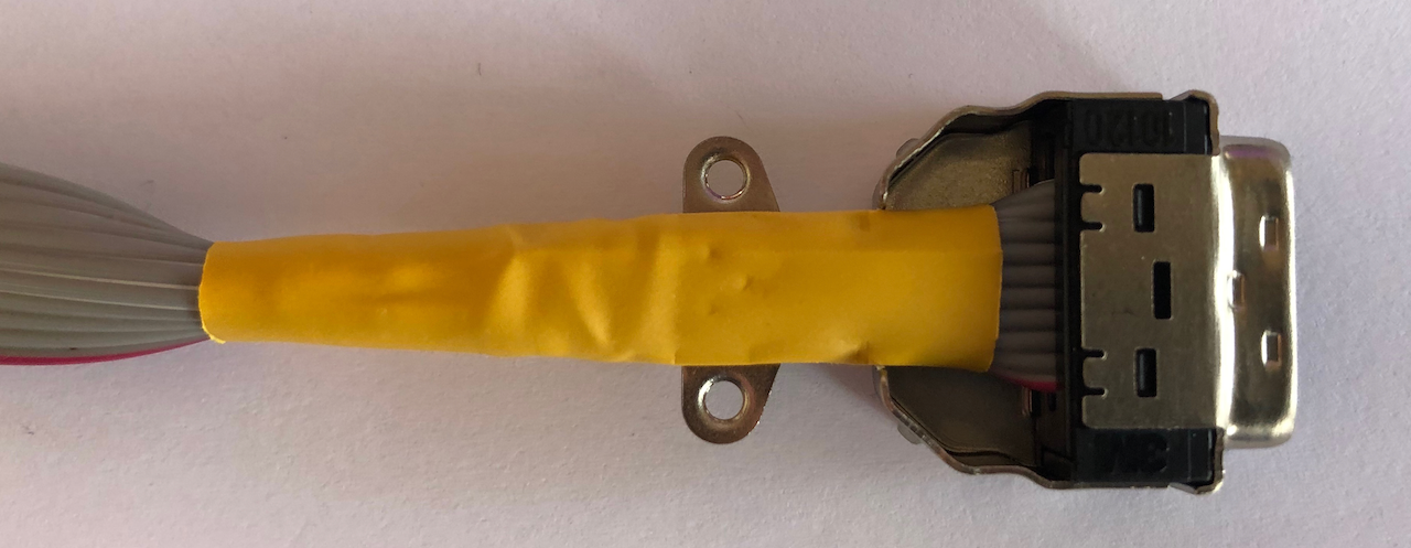
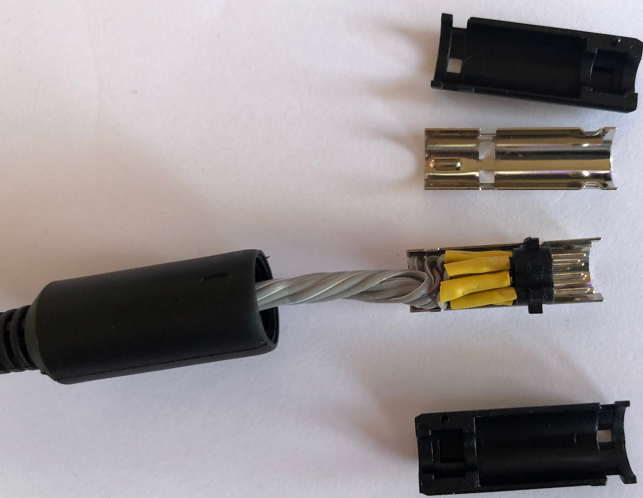
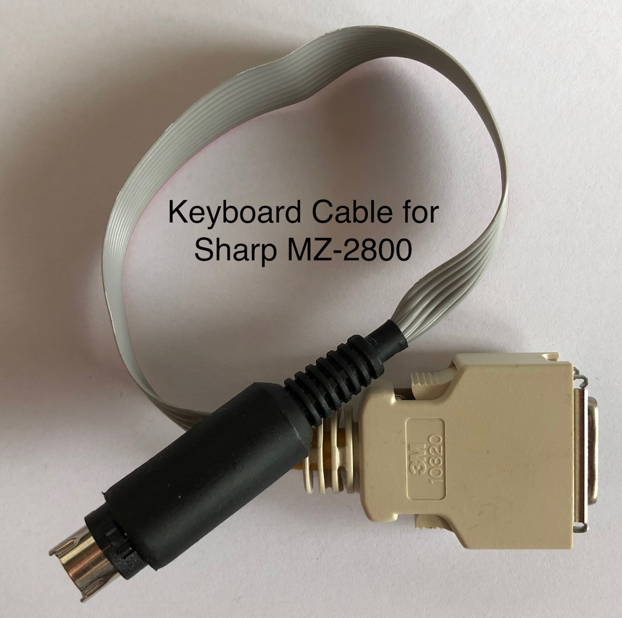
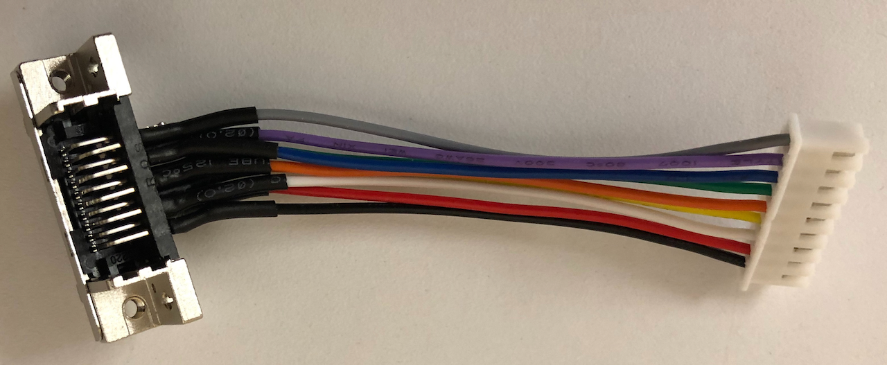
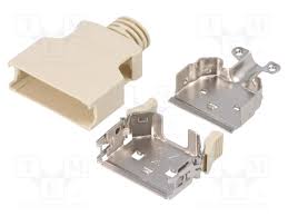
First step is to make up a cable from the SharpKey to the MZ-2800 using an alternative 3M plug. The part number for the plug is 3M 10120-6000L and can be seen in the pictures below along with the casing and hood.
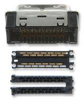
The plug is an IDC component (ribbon cable is compressed onto receptacle pins in the plug) and requires a length of 9pin ribbon cable with one side having a red identifier colouring.
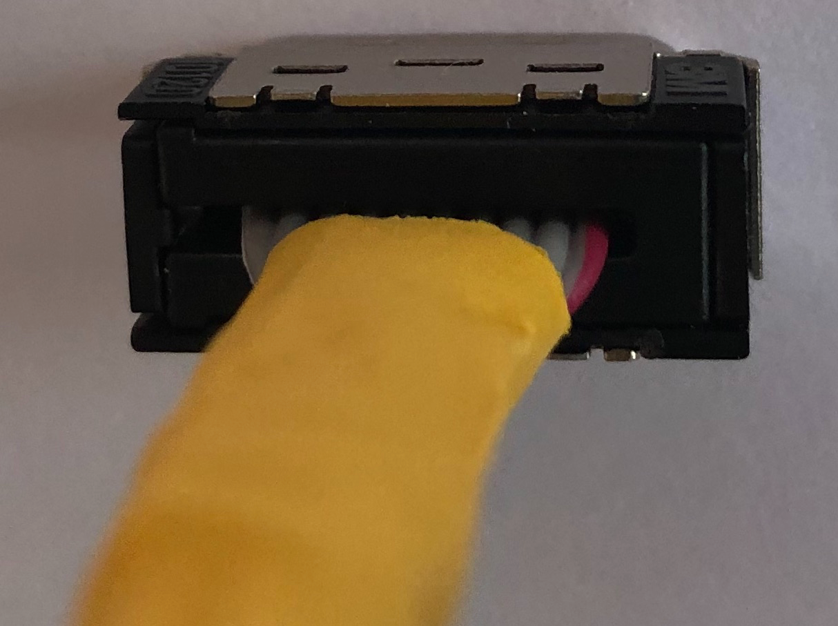
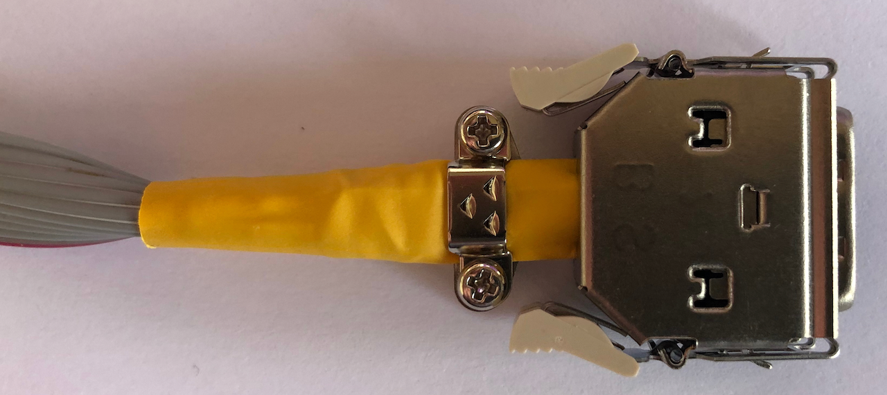
The following photos show how the cable is made. The 9pin ribbon cable is compressed onto the top set of pins (the 3M plug has an upper bank of 10 pins and a lower bank of 10 pins) with the red identifier cable at the right side onto pin 1. After compressing the cable, a length of heat shrink or similar material
must be placed over the ribbon cable to prevent chaffing on the metal case (from experience, the first example made chaffed and burnt the plug pin 1).
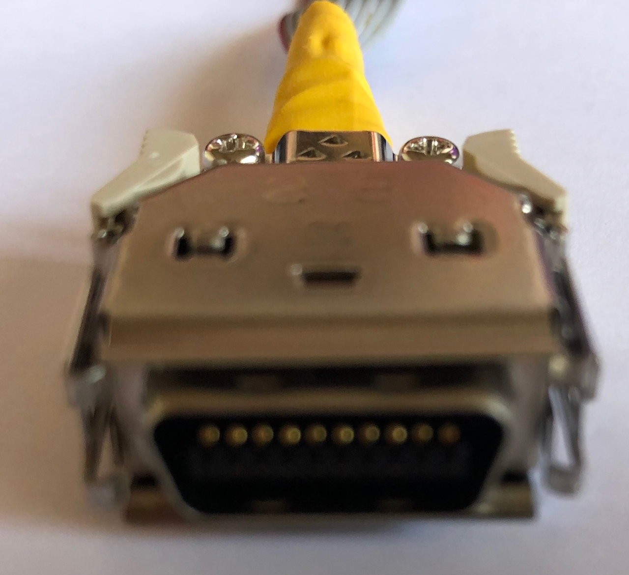
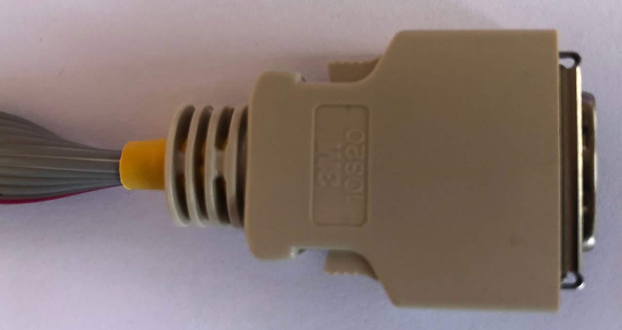
The ribbon cable and plug are then placed into the metal case and secured with the cable clamp screws. The case lid is placed on top followed by the hood.
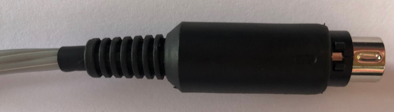
The unconnected end of the ribbon cable is then wired according to the diagram below, the red identifier cable is Pin 1, ie. 5V.
Use heat shrink shielding on each of the soldered wires to prevent short circuits, the finished plug will appear similar to the images below.
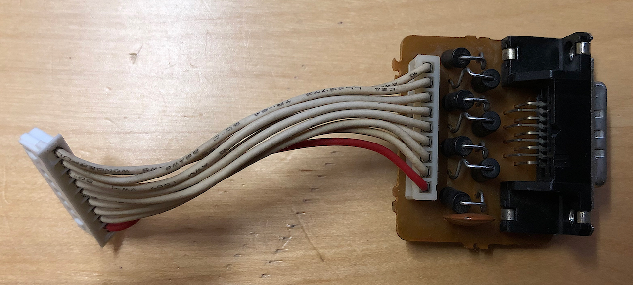
Once the SharpKey to MZ-2800 3M cable is made up you will need to remove the original AMP 9pin D-Sub from the MZ-2800 case. This is simply a matter or removing the lid, unscrewing the 2 screws afixing the AMP 9pin D-Sub to the casing and unplugging the 9pin 2.5mm JST PCB wire mount plug from the mainboard. The original AMP socket, once removed will appear as below:
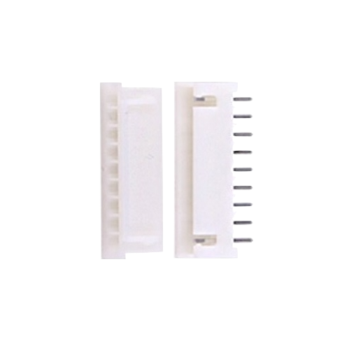
Now the fun begins! Not only is the AMP 9pin plug unavailable, the JST 9pin PCB plug (left of photo above) is also unavailable with the nearest equivalent being a JST XH 2.5mm 9 way, ie.
The difference between this connector and the original is the width of the pins, the original using blade pins, the new one using square needle pins. The needle pin plug, which uses female receptacles wont easily fit onto the mainboard original socket which has male blade pins. It is possible to widen out the female pins on the new plug and then force the plug into the socket
but I chose to replace the socket on the mainboard with a JST XH 2.5mm 9 way socket.
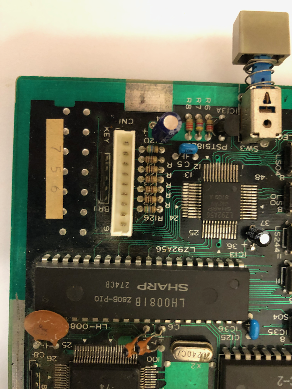
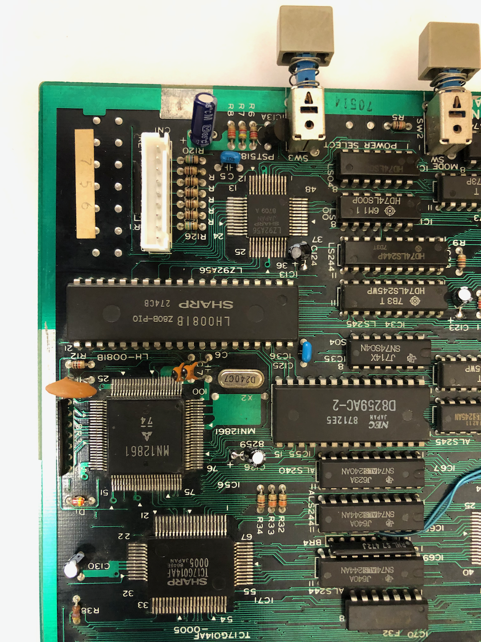
To replace the socket requires disassembly of the MZ-2800, removal of the mainboard, desoldering of the original socket and replacing with the new socket. The images below show original (left) and new (right).
The next stage is to make up a JST XH 2.5mm 9 way plug to 3M socket, 3M part number 10220-5212PL which appears below.
The easiest way is to buy a pre-wired JST XH 9way plug and solder the cable ends to the 3M socket using the diagram below. Use heatshrink sleeving on each wire to prevent shorts especially as the 3M Socket once mounted inside the MZ-2800 casing is very close to the mainboard and could short.
The finished assembly after wiring should look like this:
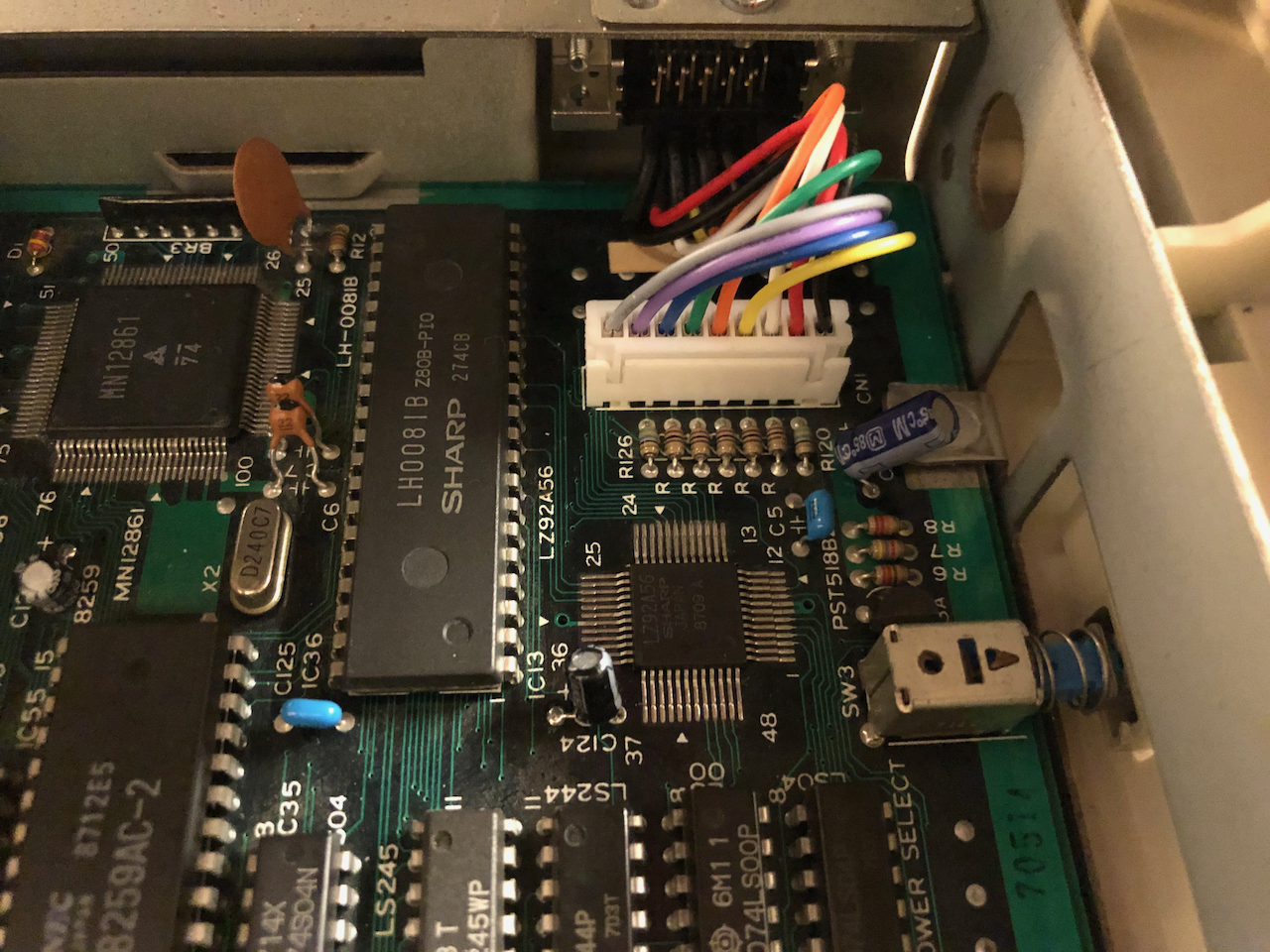
Now install the socket into the MZ-2800 casing securing with the 2 screws removed earlier and plugging the JST XH 9way plug onto the motherboard socket. Image below shows the fit and finish:
Testing of the cables should be made at regular intervals to verify correct pin to pin and no short circuits. Before powering up the MZ-2800 make a final test from the JST XH socket on the motherboard to the mini-DIN8 which plugs into the SharpKey to verify pins are wired correctly and no short circuits.
Sharp X1 Cable
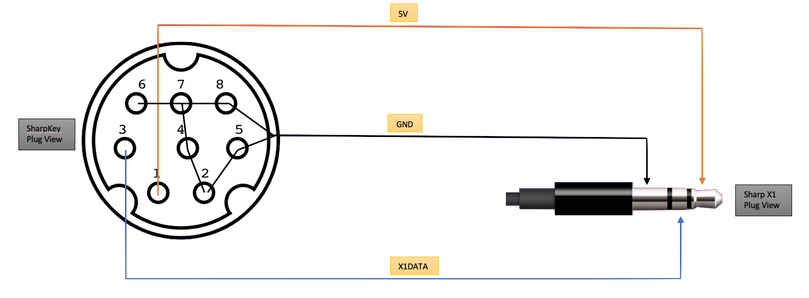
The Sharp X1 keyboard port uses a 3.5mm Stereo Audio Jack. A cable needs to be made using the diagram below between a 3.5mm Stereo Jack on the X1 side and a mini-DIN8 plug on the SharpKey side.
Pay attention to pins 2, 4, 5, 6, 7 & 8 on the mini-DIN8 which need to be grounded, ground connecting to the metal frame of the mini-DIN8 plug. This is necessary for the SharpKey firmware to detect the host.
The X1 has two issues regarding the 5V power supply at the keyboard port which can be rectified with a small internal change. The issues being current is limited to 50mA via an internal 100R resistor on both the front and rear keyboard sockets. Secondly, the keyboard is supplied by the 5V standby circuit with minimal power rating
and will brown out above 100-200mA.
The SharpKey takes approx 30mA when running in addition to the PS/2 keyboard/mouse requirements.
If you are connecting the SharpKey to a KVM and then to the X1 no change is required albeit the WiFi interface wont work in Client Mode, only Access Point mode.
If you are connecting the SharpKey direct to a PS/2 Keyboard and then to the X1, the internal 100R resistor will need to be changed to 33R 1/2 watt, albeit, the standby circuit cannot provide sufficient current to power the ESP32 WiFi transceiver when it starts in Client Mode (it uses max transmission power and I havent found a way to prevent this) so only
Access Point mode will be available. The SharpKey typically consumes 150mA once the WiFi mode has started and stabilised.
The best solution, on one of the keyboard ports only (keeping the second original) is to remove the internal 100R resistor and place a new 500mA fuse between the keyboard port power pin and the standard 5V supply, which on the front keyboard port can be found adjacent to the port 3pin JC connector, it has a 5V power plane copper fill next to it. This
change will allow the SharpKey to operate in both WiFi Access Point and Client modes as well as powering the PS/2 keyboard/mouse reliably.
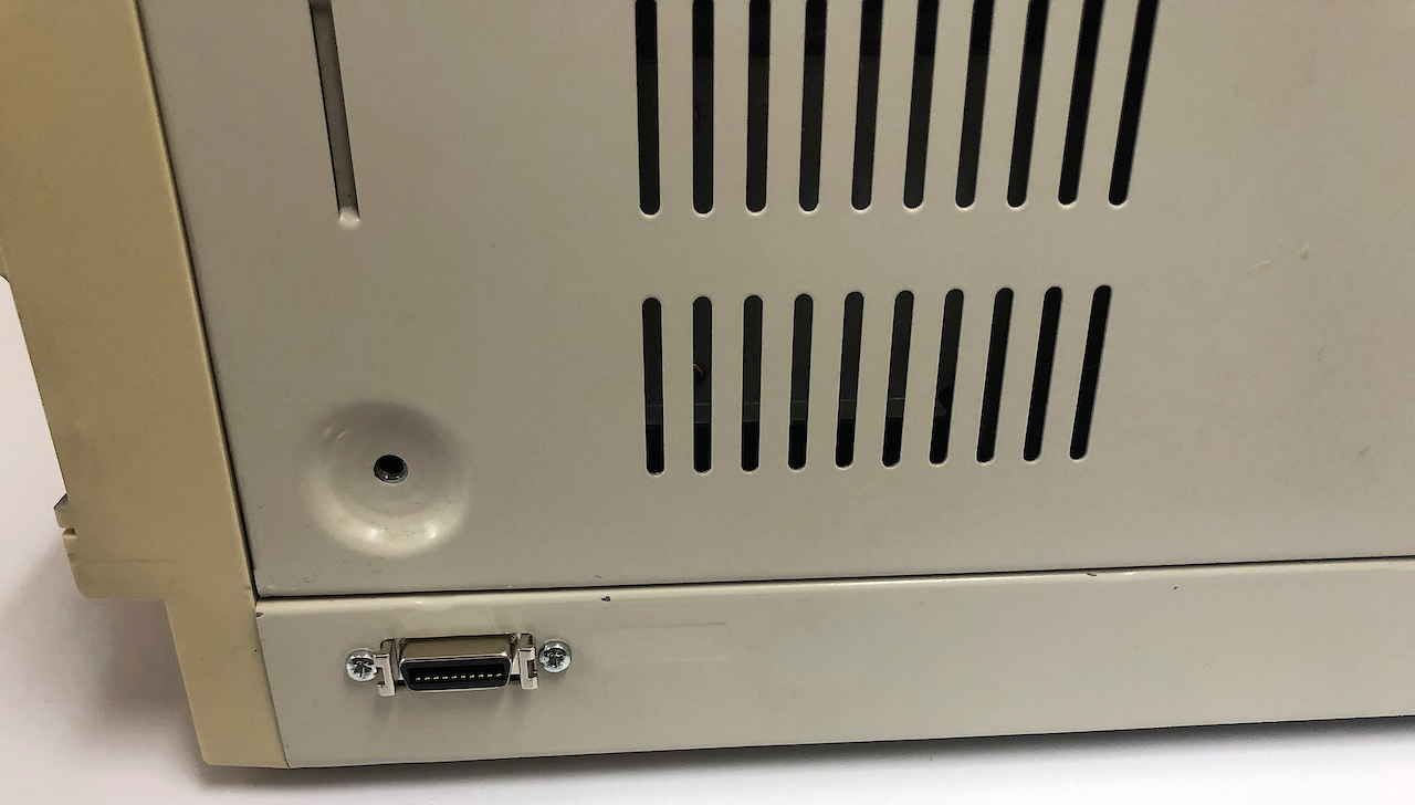
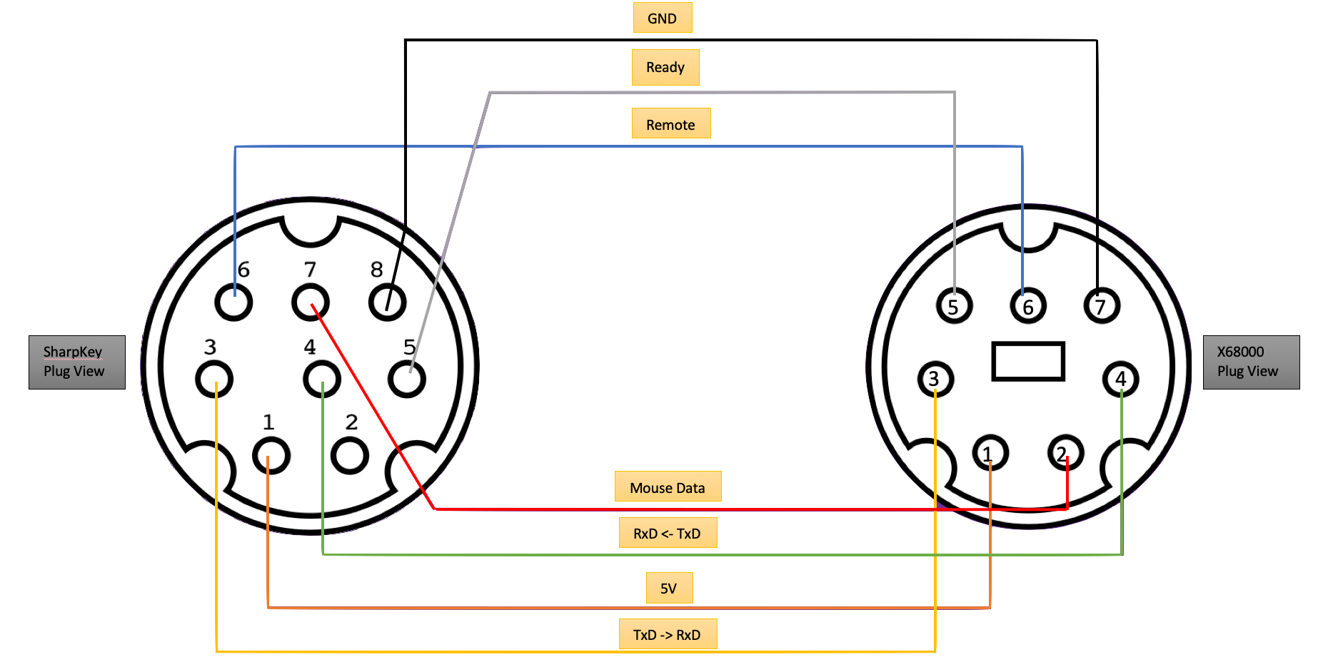
Sharp X68000 Cable
The Sharp X68000 keyboard port uses a mini-DIN7 socket. A cable needs to be made using the diagram below between a mini-DIN7 plug on the X68000 side and a mini-DIN8 plug on the SharpKey side.
Pay attention to pins 7 & 8 on the mini-DIN8 which need to be grounded, ground connecting to the metal frame of the mini-DIN8 plug. This is necessary for the SharpKey firmware to detect the host.
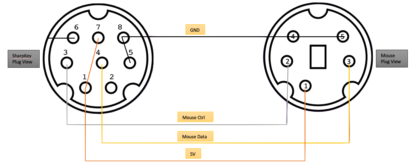
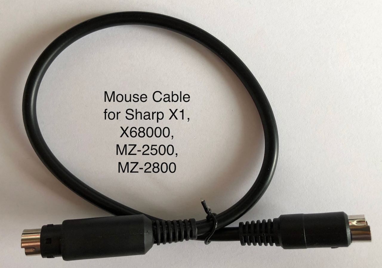
Sharp Mouse Cable
The Sharp Mouse port on the X68000, MZ-2500, MZ-2800 and X1 uses a mini-DIN5 socket. A cable needs to be made using the diagram below between a mini-DIN8 plug on the host Mouse port side and a mini-DIN8 plug on the SharpKey side.
Pay attention to pins 5, 6 & 8 on the mini-DIN8 which need to be grounded, ground connecting to the metal fram of the mini-DIN8 plug and pin 7 which needs to be connected to 5V which is on pin 1. This is necessary for the SharpKey firmware to detect the host.
Assembled Interface
The pictures below highlight the completed, assembled and working interface.
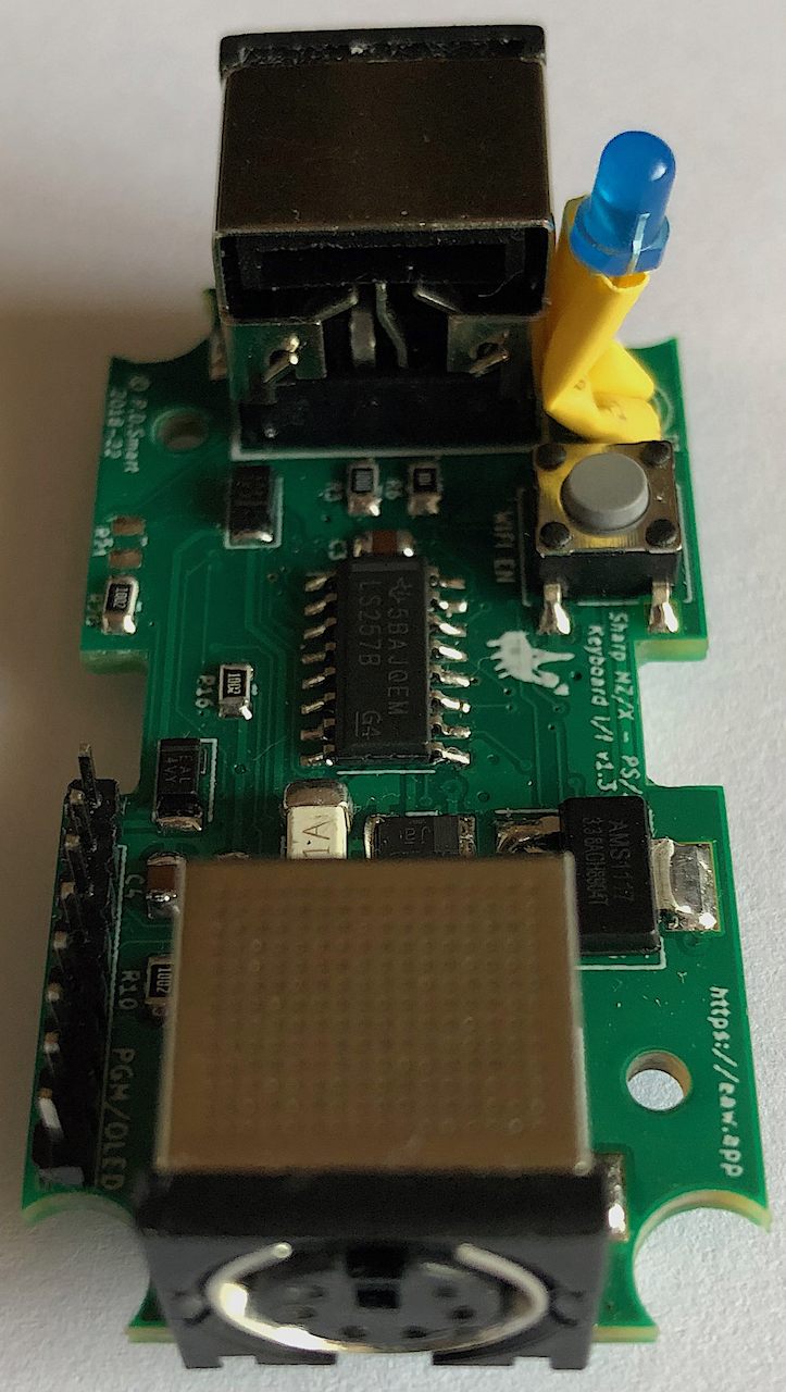
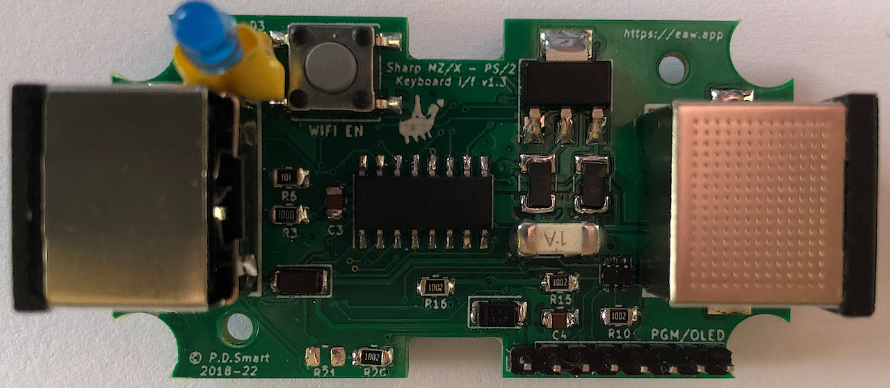 Top side of the interface, there are some optional components installed such as the 2mm 8pin programming header and R21 which is DNP. During development it was noted that the host keyboard/mouse port voltage would frequently be lower than 4.8v so D1 is replaced with a solder bridge as it is not needed unless the board is
being used for development with a UART programming interface as it prevents current flow into the host.
Top side of the interface, there are some optional components installed such as the 2mm 8pin programming header and R21 which is DNP. During development it was noted that the host keyboard/mouse port voltage would frequently be lower than 4.8v so D1 is replaced with a solder bridge as it is not needed unless the board is
being used for development with a UART programming interface as it prevents current flow into the host.
Fuse F1 in the assembled board is using a 1Amp fuse as this board is being used for development, for general use this should be 250mA-500mA. Some of the component identifiers are under the components, this was
intentional, only components which were too small have the part designator seperate.
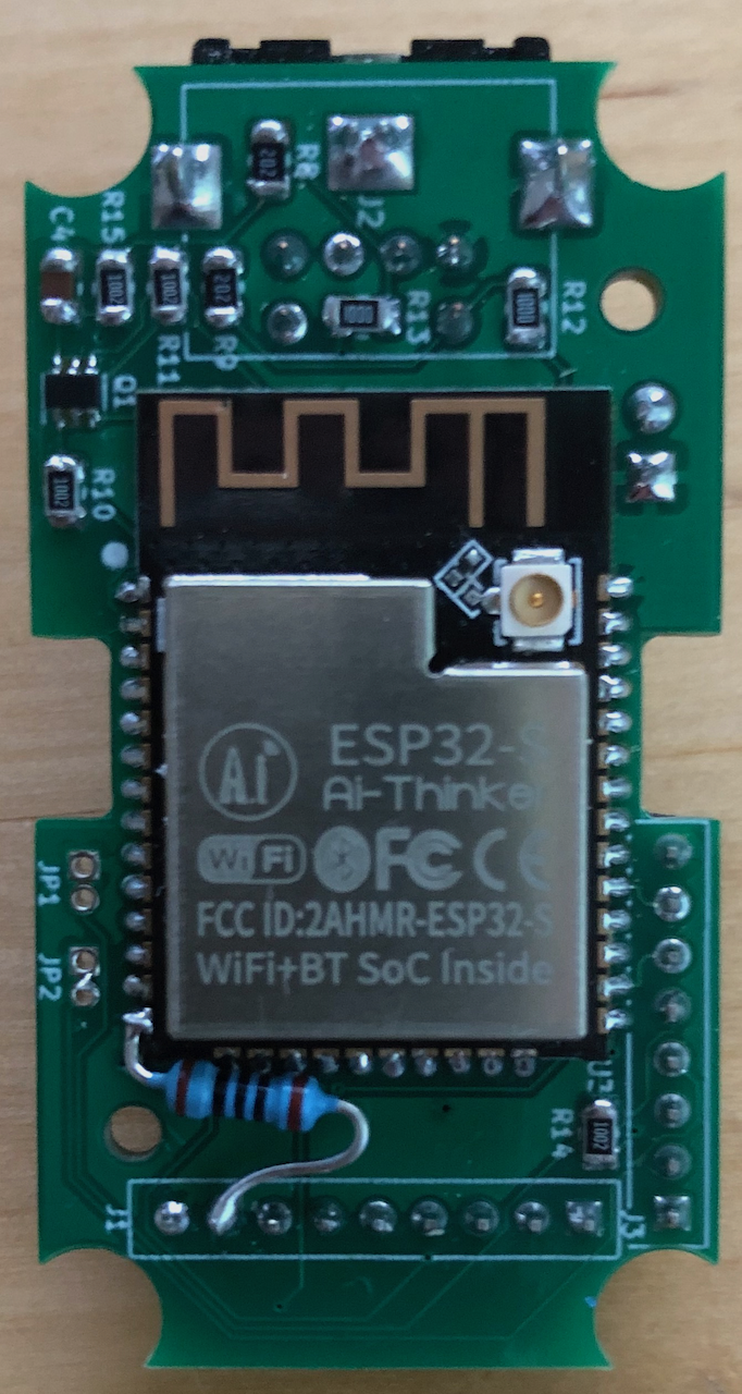
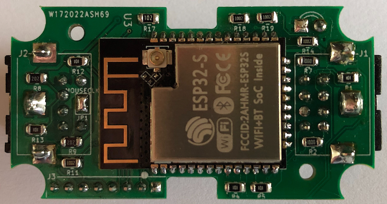 The underside of the interface, the ESP32 takes up most of the space.
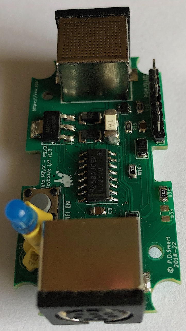
Side view of the board, looking at the mini-din8 connector which connects with the host computer.
Side view of the board, looking at the mini-din6 connector which connects with the PS/2 device.
 Installation inside a KM-24 case which is a tight fit.
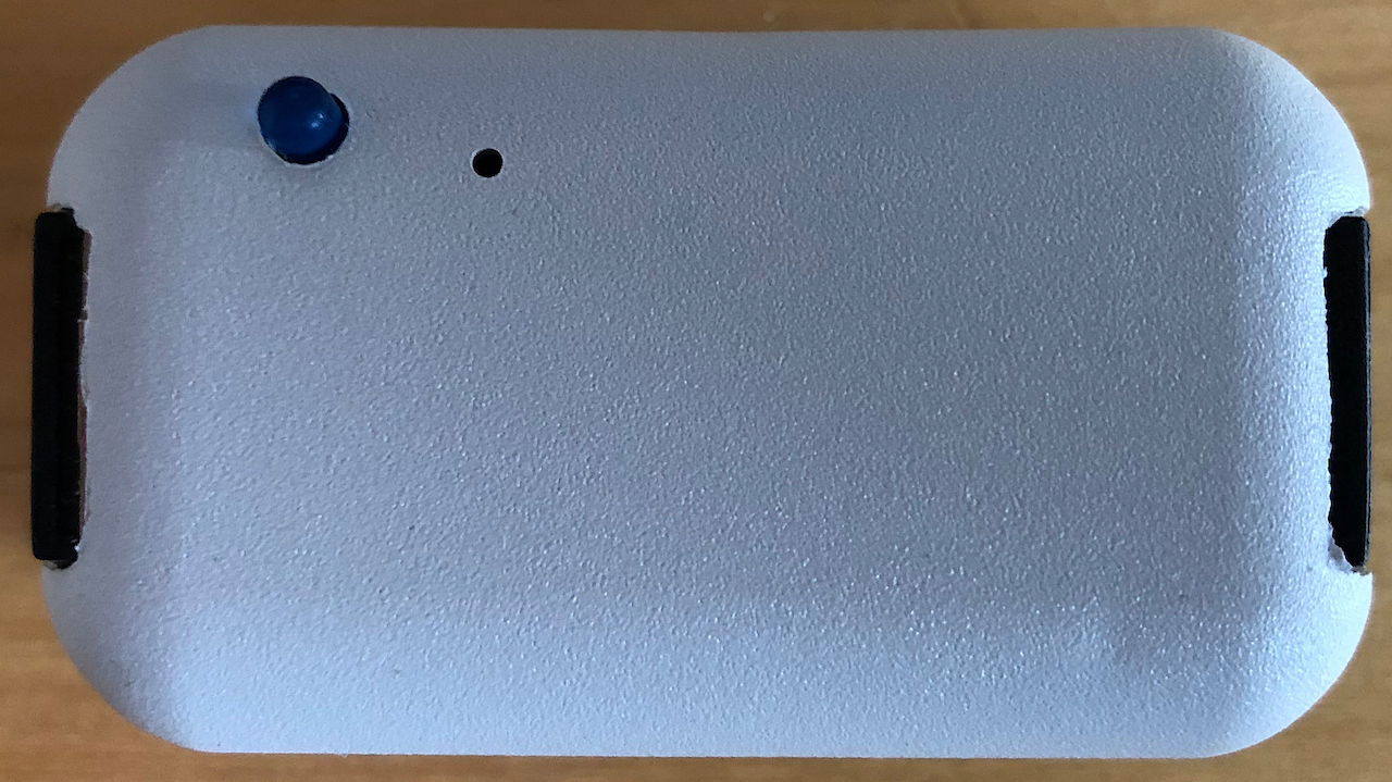 Top of the assembled unit with a pin-hole to allow enabling of the WiFi/Bluetooth pairing.
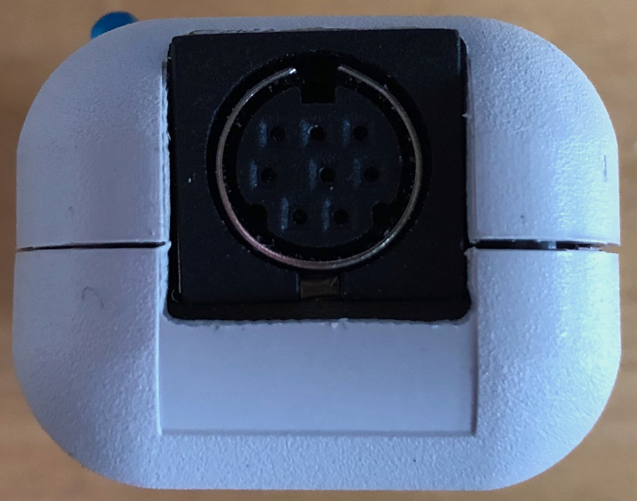 Mini-DIN8 Host Connector. Cable goes from this port, via a custom cable, to a Host Keyboard/Mouse port.
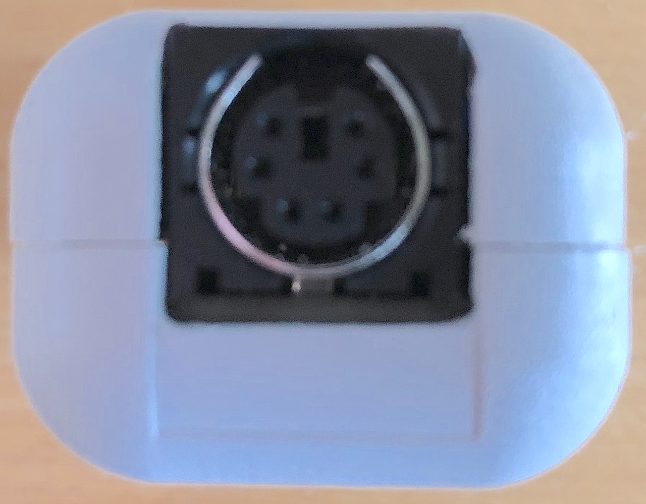 Mini-DIN6 PS/2 Connector. A PS/2 Keyboard or Mouse plugs into this port.
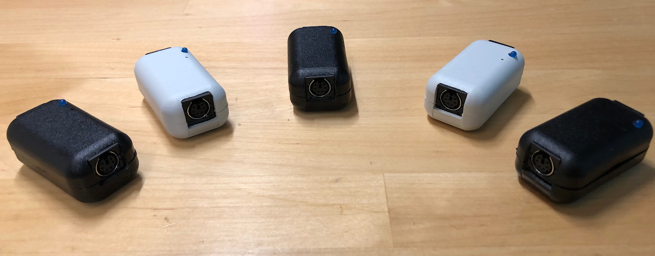 Initial 5 SharpKeys destined for my own computers, together with 2 modified mz25key units (a small internal change allows an mz25key to run the SharpKey firmware) provides keyboard and mouse functionality to all the machines.
Modification required to an mz25key to allow it to run SharpKey firmware. A 100R resistor is placed between pin14 (GPIO12) of the ESP32 and pin 8 of the host interface header J1.
Reference Manuals
The following documents were referenced in the creation of the SharpKey and its firmware.
Links
The following links were referenced in the creation of the SharpKey and its firmware. They provide a wealth of information in understanding the Sharp and NEC machines.
| Site |
Language |
Description |
| Kyoichi Sato’s X68000 Interface |
Japanese |
An excellent document on an early X68000 keyboard interface with many useful titbits of information. |
| X1 Center |
Japanese |
A very informative site on X1 details and repairs. Use Google Chrome and in the top left corner you will see, in Japanese, Use Frames Yes/No, click on No - ie the following underlined characters to ensure Google translates the site. フレーム有り/無 し |
| Kyoichi Sato’s X1 Interface |
Japanese |
An excellent document with details of an early Renesas R8C based interface which gave me many inspirations. |
| Sharp Museum by Oh!Ishi |
Japanese |
A comprehensive museum of all Sharp computer products. Use Google Chrome and click on the X1/X1 Turbo links for further details. |
| Maroon DTI |
Japanese |
A good source of MZ-2500 information, some of which I translated and stored above, ie. Keyboard Protocol. |
Credits
Espressif IDF development environment and use of the ESP-32S reference material was used in the design of this keyboard interface.
Youkan's site for initial details of the MZ-2500 protocol. The MZ-2800 protocol I had to work out myself as nothing is published on the web.
X1 Center along with
Kyoichi Sato's site for insight information into the Sharp X1 keyboard protocol.
TMK and
Kyoichi Sato's site for insight into the X68000 keyboard protocol.
There is very little detail of the Mouse protocol, many links no longer work, so most of the protocol I had to work out with a little help from this PIC based mouse
source code which is used on
Martin's mouse
adapter.
Licenses
This design, hardware and software, is licensed under the GNU Public Licence v3.
No commercial use to be made of this design or any hardware/firmware component without express permission from the author. This condition overrides
any rights afforded by the GNU GPL 3 license.
The Gnu Public License v3
The source and binary files in this project marked as GPL v3 are free software: you can redistribute it and-or modify it under the terms of the GNU General Public License as published by the Free Software Foundation, either version 3 of the License, or (at your option) any later version.
The source files are distributed in the hope that it will be useful, but WITHOUT ANY WARRANTY; without even the implied warranty of MERCHANTABILITY or FITNESS FOR A PARTICULAR PURPOSE. See the GNU General Public License for more details.
You should have received a copy of the GNU General Public License along with this program. If not, see http://www.gnu.org/licenses/.