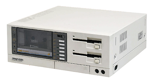
 Sharp MZ-2500 Upgrades
Summary
This machine not only runs MZ-80B/MZ-2000/MZ-2200 software but makes a big jump in terms of video, audio, memory and expansion for its own software. I'm looking forward to seeing if I can further upgrade it with the tranZPUter or tranZPUter SW design to upgrade the Z80 CPU to 24MHz and provide SD services accordingly.
The MZ-2500 already has colour video output with 64K Graphics VRAM, Character VRAM and a PCG with Kanji support so it makes no sense to adapt the Video Module to this machine.
After working with the MZ-2500 for the last few months, the machine is very difficult to upgrade other than using an expansion card. There is no space for a tranZPUter unless I copy Sharp's 8086 expansion for the MZ-2000 and use a 40pin fly lead and site the tranZPUter elsewhere.
I thus decided not to pursue the tranZPUter upgrade path for this machine and just get to know it so that I can add an MZ-2500 emulation into my FPGA Sharp MZ Series emulator in due course.
Renovation Begins
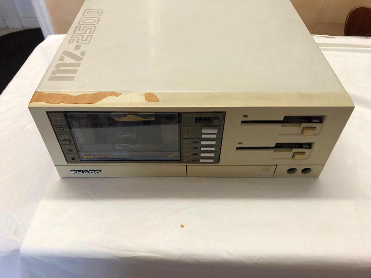
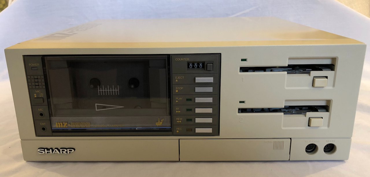
This is the first (of two) MZ-2500 I’m working on, externally it doesnt look too bad but a long time ago someone stuck packing tape over it and it has aged and discoloured the plastic.
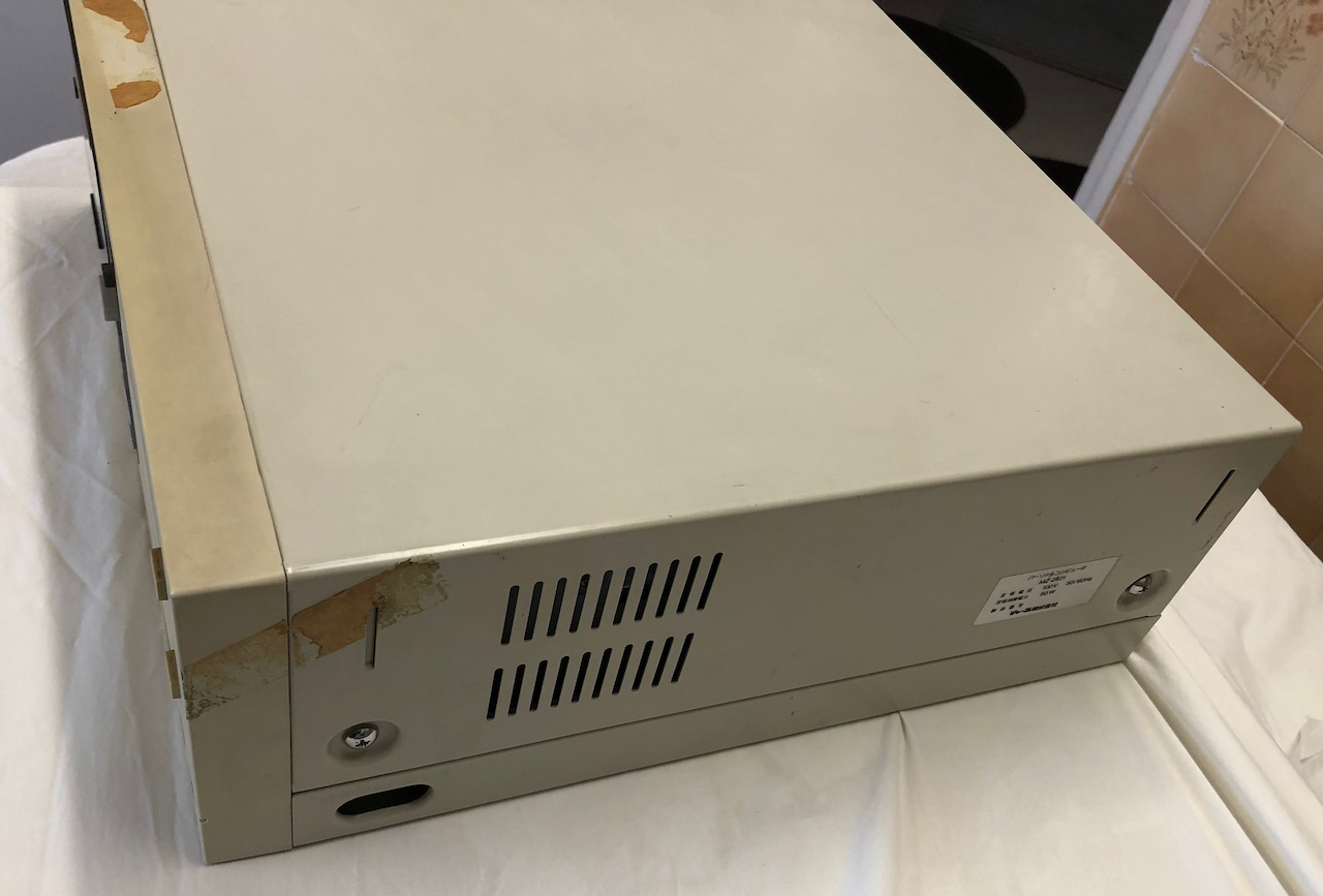
Side image where the packing tape terminates.
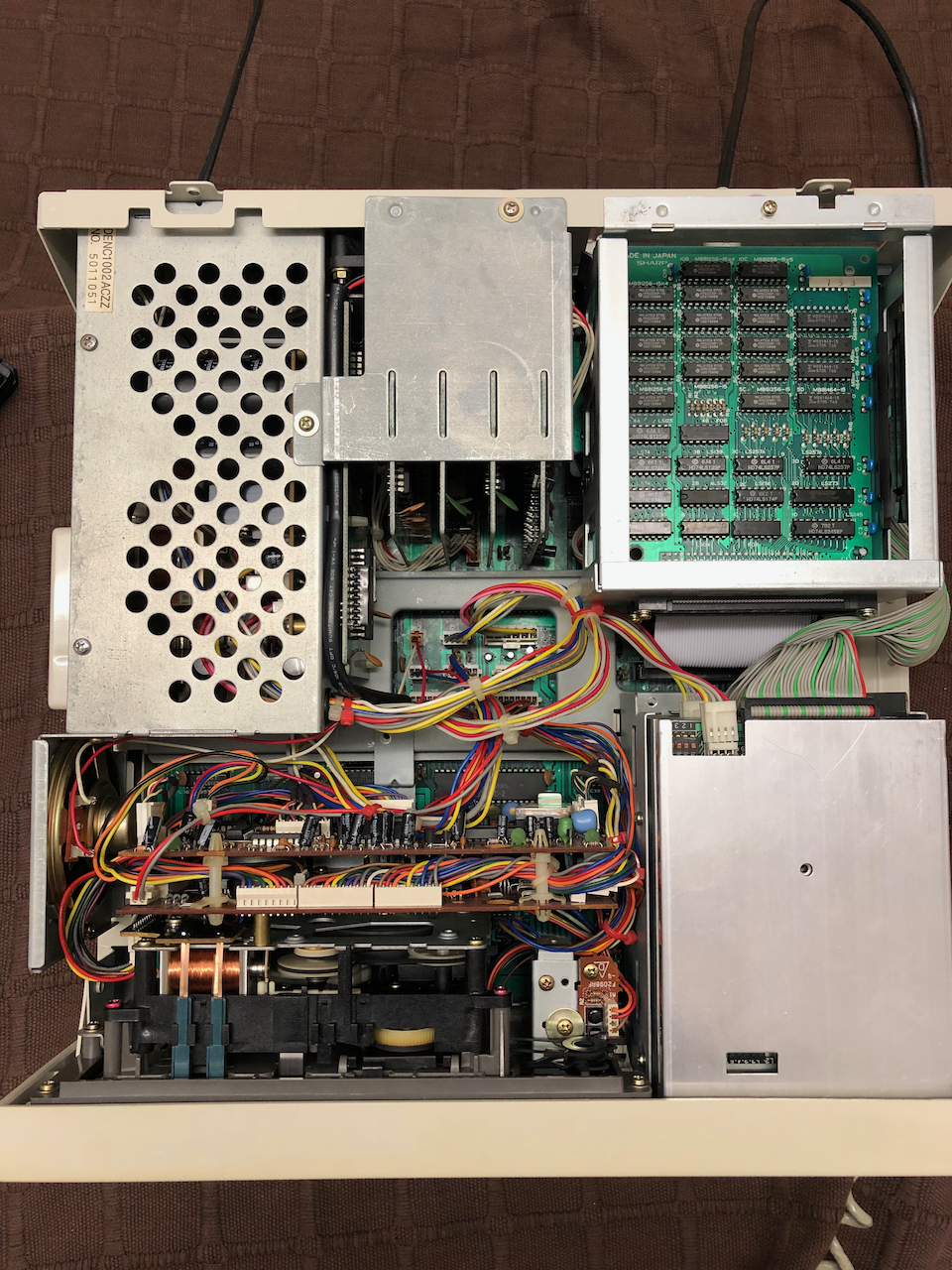
Internally the machine looks good, very little signs of rust which I’ve encountered on many machines from Japan. I’m guessing the sea air, like the UK, attacks the metal work when they are stored.
As can be seen, the machine is fully loaded with all the options. It even has an MZ-2000 Kanji ROM card which seems out of place, I will put this card in my MZ-2000!
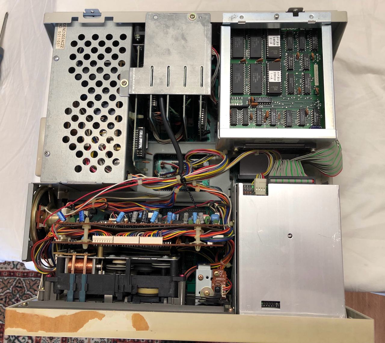
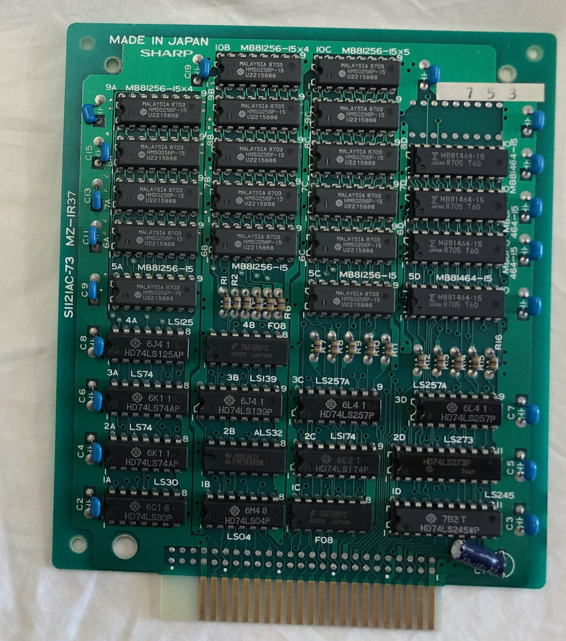
First expansion board, an MZ-1R37 640KByte EMM card. This card adds 640Kbyte additional RAM which is typically used for a RAM disk.
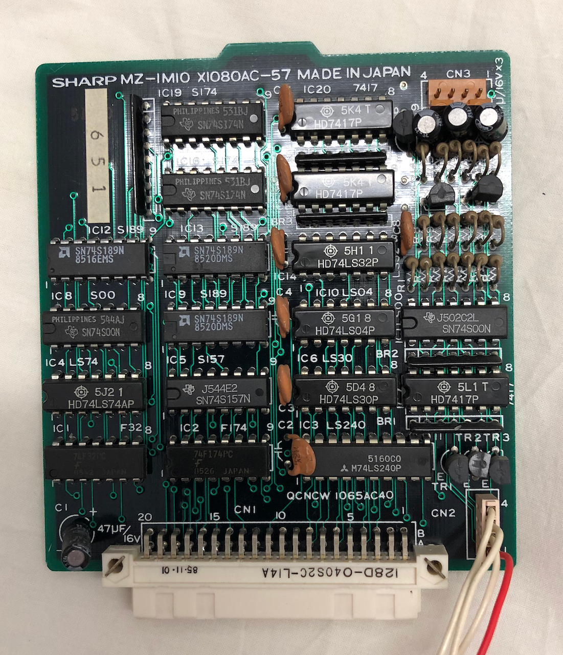
Next up is am MZ-1MIO board, this card adds a 4096 colour capability to the MZ-2500 using a colour palette.
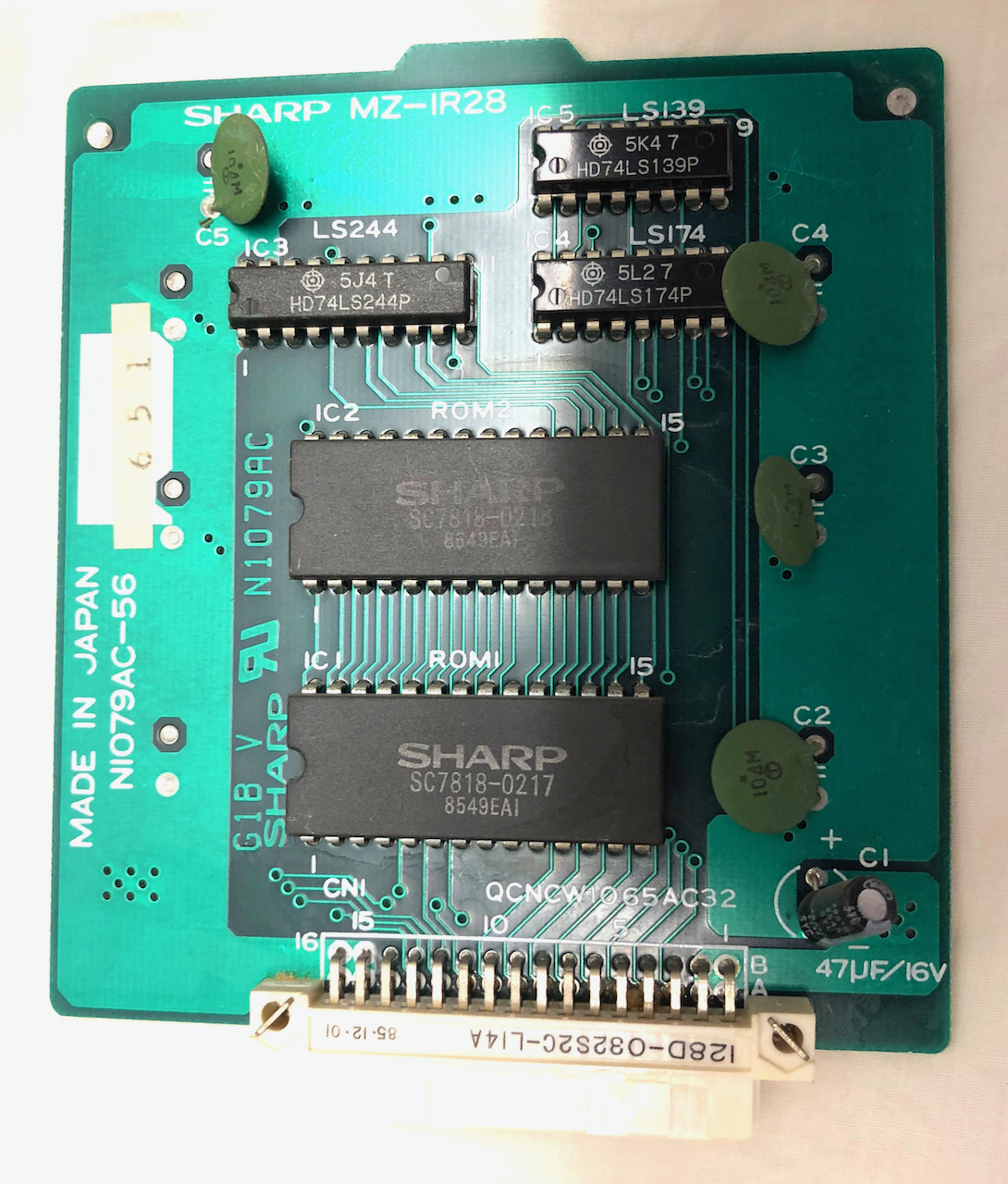
Next is an MZ-1R28 board, this board adds Hiragana to Kanji translation dictionary.
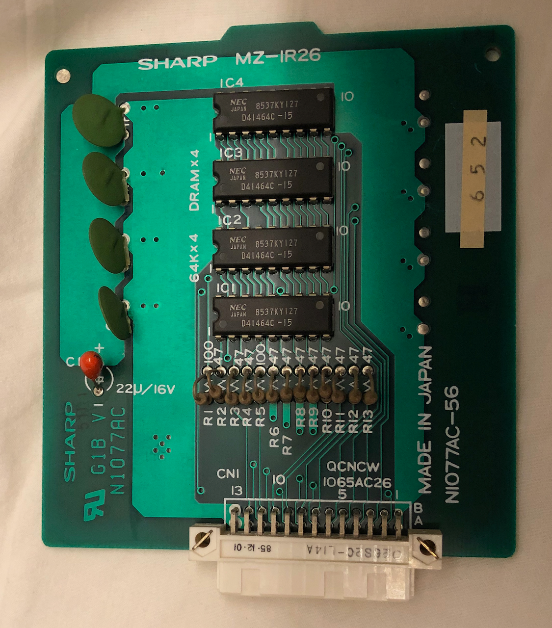
Next is an MZ-1R26 128KB RAM expansion card, increasing the MZ-2500 memory from 128KBytes to 256KBytes.
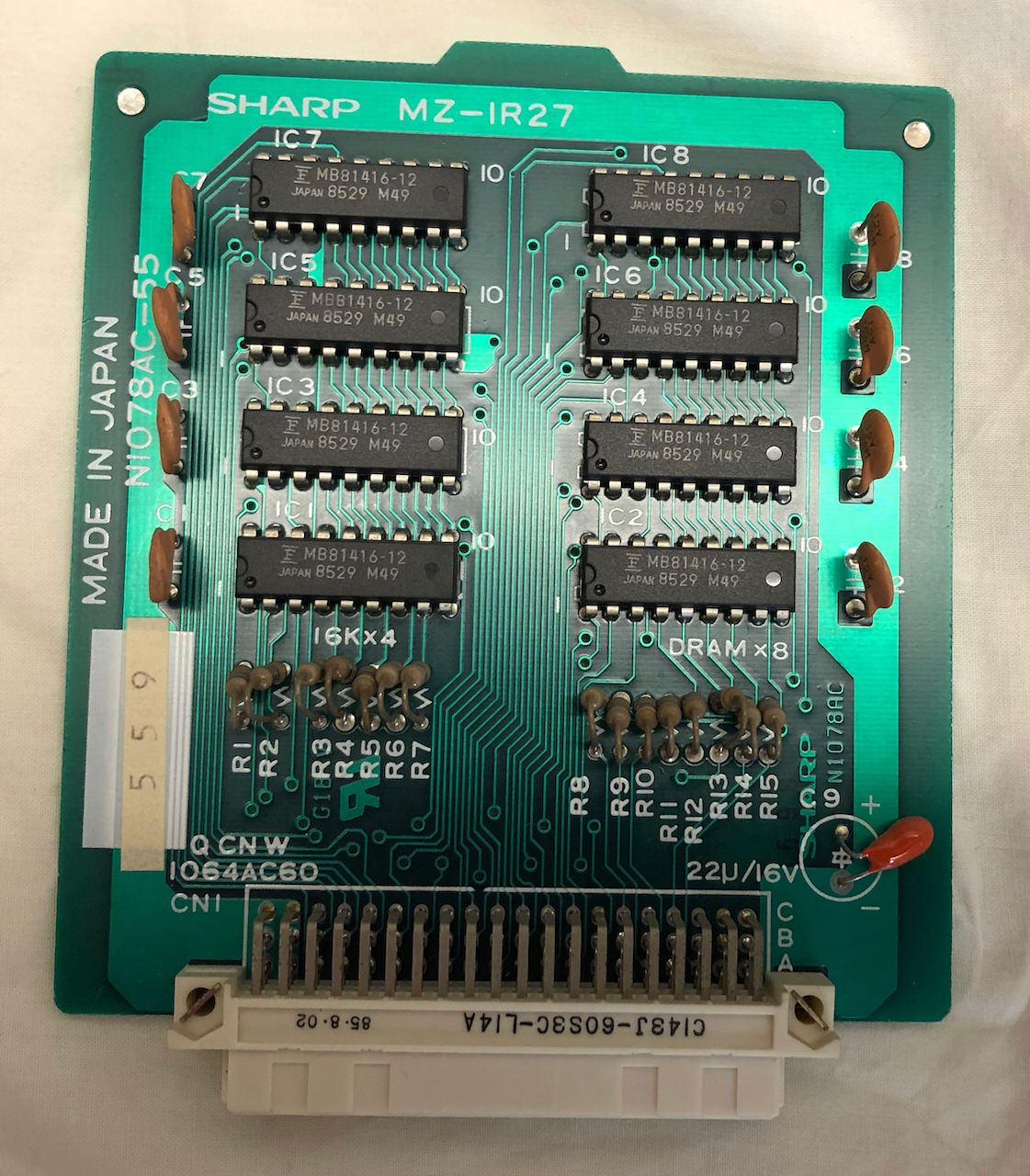
Finally an MZ-1R27 64KByte Video RAM expansion card, increasing the MZ-2500 video RAM to 128KBytes.
It took quite a while to remove the packing tape, it had set like super glue and after removal and full clean, the discoloration wasnt, to me, acceptable. Where the packing tape was located the machine was almost original colour and everywhere else was varying shades of yellow. Not something I would have prefered to do but a little retrobrite had to be applied to get the plastic to a uniform colour. It is still a slight yellow but uniform across the whole front bezel now. Harsher retrobriting would have brought the front bezel to original white colour but I considered this and wanted the machine to have some of it's character rather than a new out of box assembly clone.
Front Bezel after renovation.
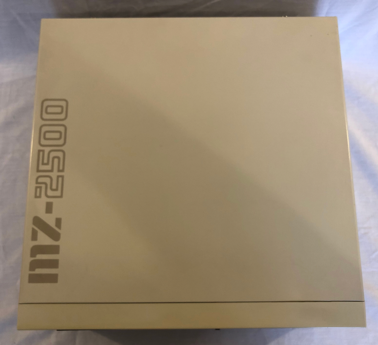
Lid, only needed a good clean.
Side, the power switch was very discoloured so I brought it into line with the front bezel.
Opposite side, just needed a good clean.
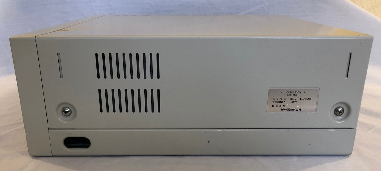
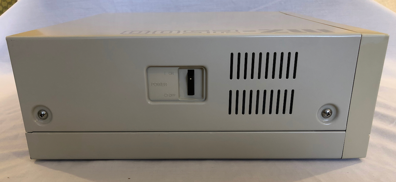
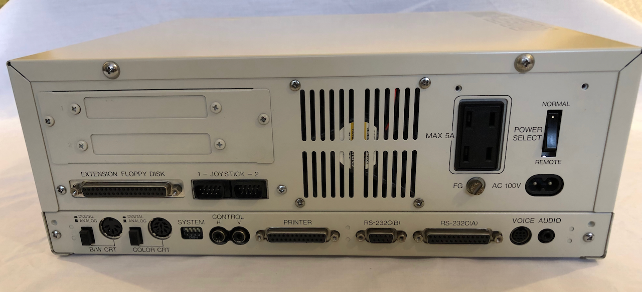
Rear panel, amazingly in very good condition, the fan was black with dust and soot but a good clean sorted the panel out.
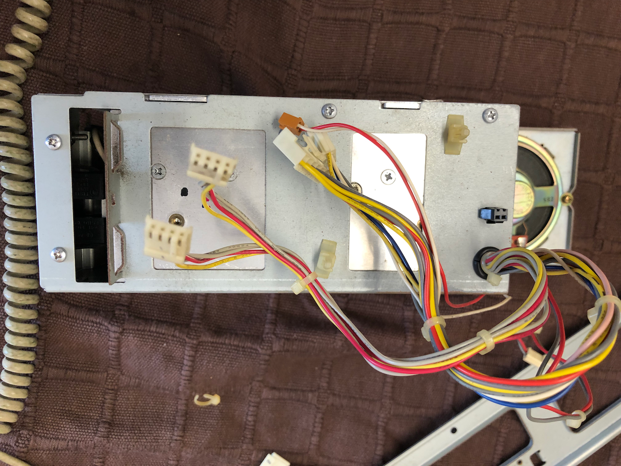
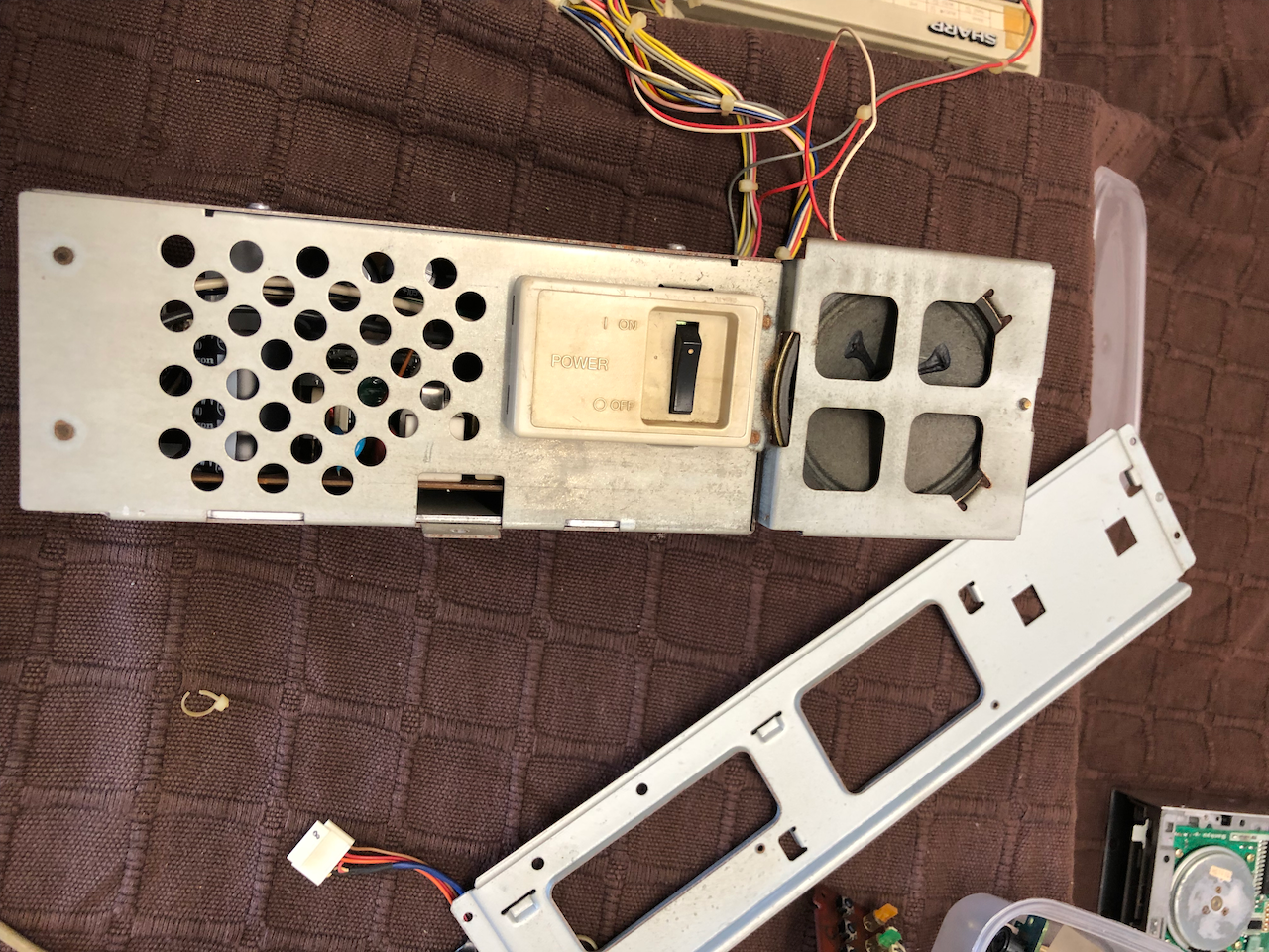
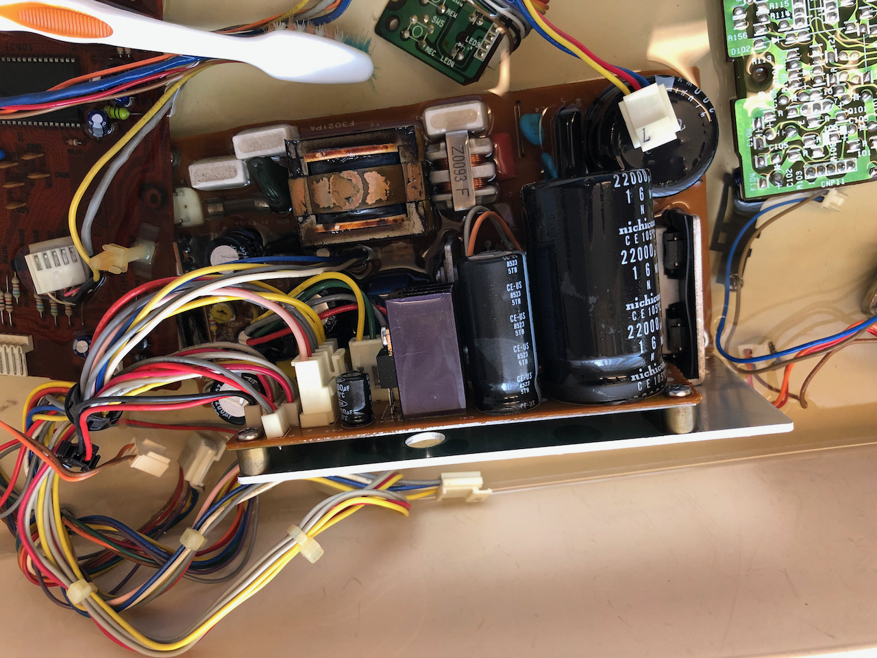
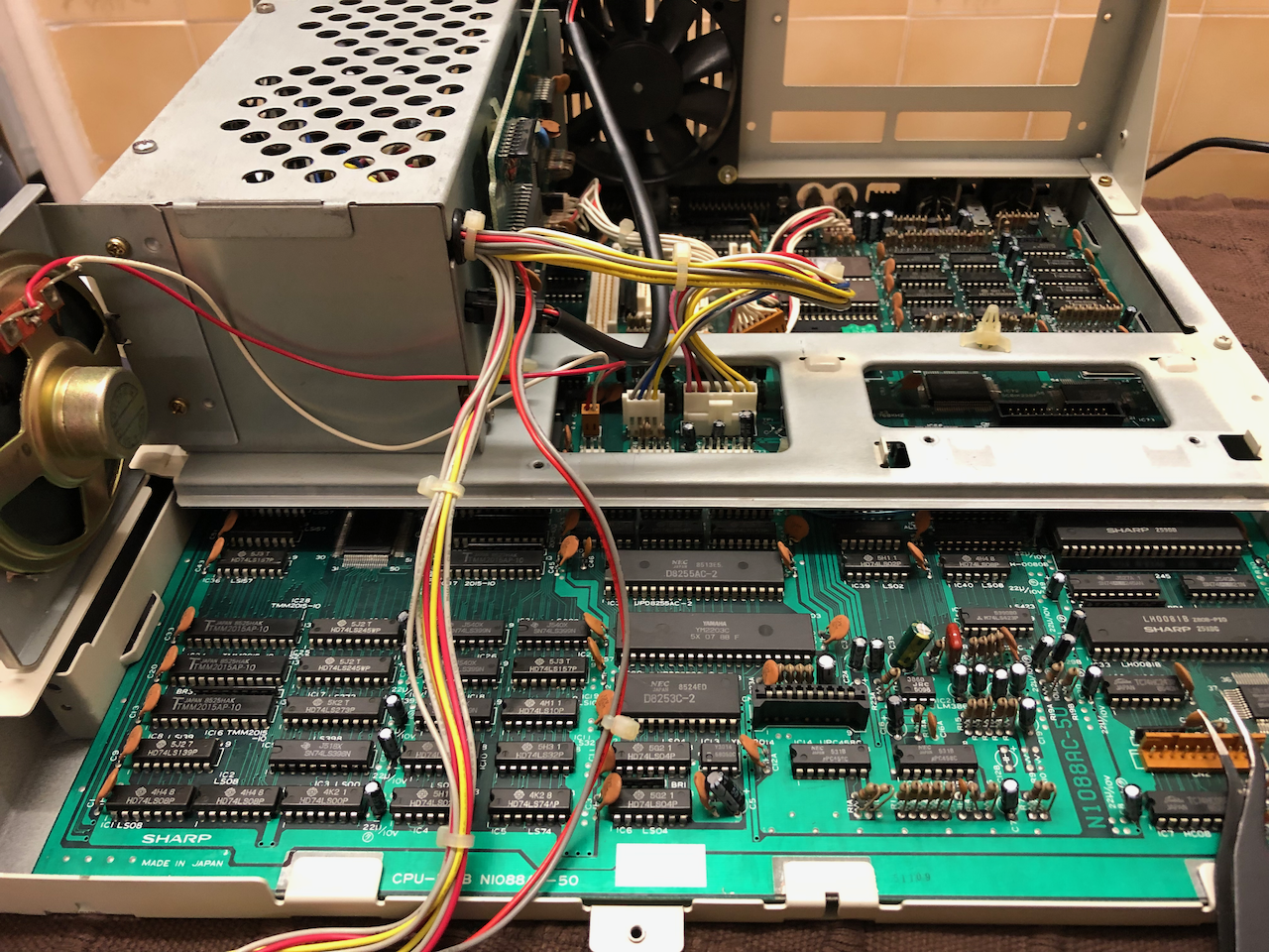
After removal of the PSU it was fully striped down and cleaned in a bath of Isopropyl alcohol, using a paint brush and tooth brush to clear and dislodged the years of 'electronic killer' gunge! The switch and external power socket were cleaned in Isopropyl alcohol and then with contact cleaner. The metal work was washed down in Isopropyl alcohol, cleaned up and then fine rust oil rubbed all over it to prevent the onset of rust.
I then set about desoldering and checking the electrolytics, replacing any which were out of tolerance by +/- 10%.
Finally, power up and check each of the voltage lines for noise and value.
Pictures below are from the 2nd unit under renovation, I forgot to take photos of the first machine as I was so engrossed!!
Another item which needs attention is the NiMH battery. On some machines they leak and damage the PCB often leaving the machine unserviceable. Luckily on this machine it was intact (Brown cylindrical device in bottom left corner below) so only required a replacement.
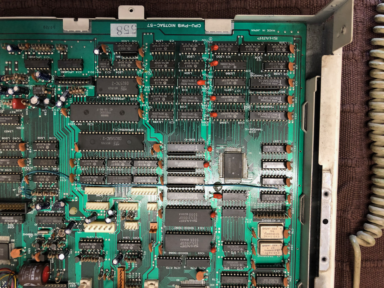
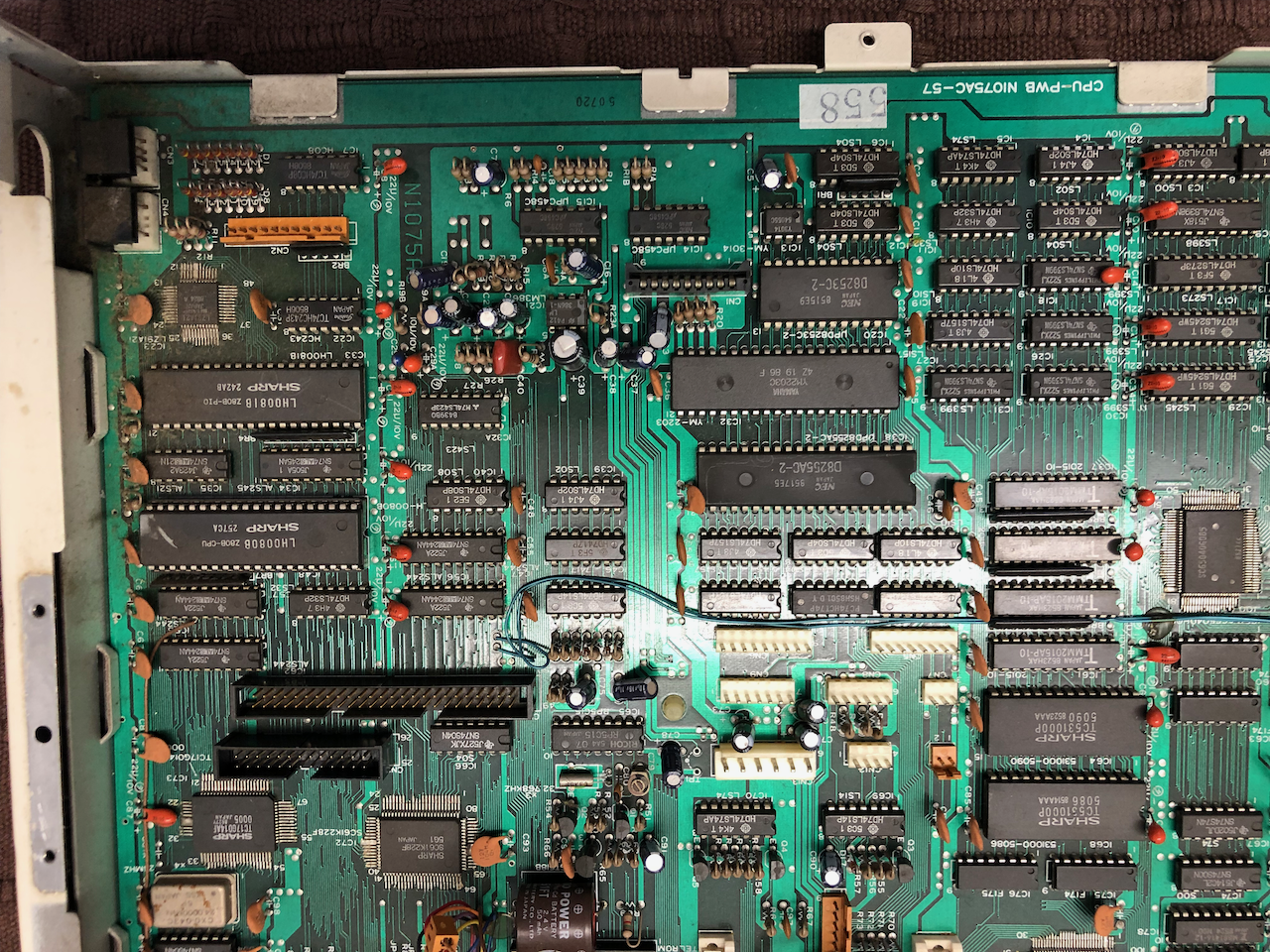
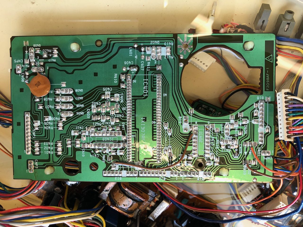
I didnt take photos of the mainboard, before/after, so below are just some mainboard photos for reference. The orange components are the tantalum bead devices.
Ever forward and onward, the 3.5" floppy drives.... once serviced I can boot a game :)
Servicing of the floppy disks amounted to disassembly and clean of all the metal work as above, cleaning of the control boards in Isopropyl alchol (the main control board) and gentle wiping and cleaning with a cotton bud of the head and mechanism. I lubricated the head control mechanism then put everything back together half expecting to delve into the wonderful world of floppy head alignment or track zero sensor replacement.
Connection to the mainboard Floppy daughter card and PSU, a prepared floppy disk (using Kryoflux) and power on.... The pleasant familiar sound of a healthy floppy disk seeking and stepping and the startup screen to Xevious... all good. I tried numerous other floppies, ie. Fenix, CP/M etc and all worked fine.
Unfortunately, the second MZ-2500 machine floppy drives had succumb to rust so this will require a lot more hard work, for now something to do on a rainy day! Maybe I can get some photos as I didnt take any of the floppy drives!!
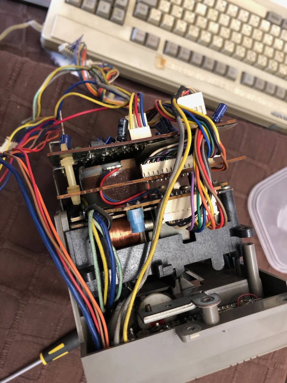
The part I had been dreading, after numerous hours working with them on the MZ-2000, the Cassette Drive.....
The cassette mechanism for the MZ-2500 is basically the same as the MZ-2000 but with stereo heads (as it can playback/record audio cassettes and telephone recordings) and more control circuitry. It comprises of 2 control boards, whereas the MZ-2000 only has 1.
As found out on the MZ-2000, the mechanism doesnt age well, the pictures below are from the second MZ-2500 I'm renovating, which externally looked better than the first, but inside was rusting and decaying.
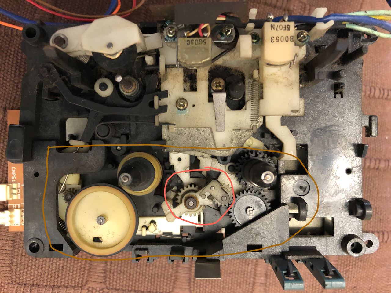
The ringed items are the main cause for concern, they are nylon cogs and with age start to crack where they are under greatest stress.
A full strip down is essential, right down to disassembling the head and drive modules. After washing with Isopropyl alcohol the first stage is to identify cracked cogs and repair them with plastic cement. I was at one stage going to get these parts 3D printed but decided against it. Another point of issue is the pinch roller, this degenerates and becomes like tar. Luckily you can still buy pinch rollers from China, so a quick order of 13x8mm pinch roller with 6mm rubber height and 2mm rubber diameter sorts this problem out.
Once the cogs are repaired, you need to set about greasing all the friction points, this part is very necessary as any friction, no matter how small can lead to some very interesting malfunctions. The flywheel top and bottom spindles need greasing, the solenoids need a little lubrication and the motor may need a drop of lubrication oil, on the 2nd MZ-2500 this was necessary due to rust.
The belts, if they have a deformation in them (ie. not round) they need replacing. The main belt is generally fine (ie. motor to flywheel) but the two smaller belts need replacing. The tape counter belt may need replacing if it has stretched or kinked, this belt is important because the tape counter sends pulse signals to the controller so it can determine if the tape is in motion, no pulse and it will stop the motor and disengage solenoids.
Re-assembling the cassette mechanism you can manually turn the flywheel and engage each solenoid to verify its smooth action and there should be very little additional force required on the flywheel during actions such as engaging the tape heads, and force means something hasnt been lubricated. I reassembled the complete tape drive and decided to test it, rewind, ffwd, play all worked fine, in MZ-2500 mode I could even play a music cassette, just one thing didnt work and it was the most important, the IPL couldnt see or interact with the cassette drive, either to eject the tape or engage play/rew/ffwd. This was also the case on the 2nd MZ-2500 and after researching some Japanese sites, a common fault but no cure was offered. I spent an age probing the 8255 and buffer drivers but couldnt find a cause, if I manually forced a signal active then the cassette drive would respond, ie. play. I then decided it was the input signals showing the CMT status but these 'seemed' in order albeit the high/low logic levels werent definitive. In exasperation and something I was trying to avoid given the sheer number, I set about replacing all the capacitors in the CMT control boards, a long task! After re-assembly, BINGO! the drive could now be seen and the IPL would correctly engage and boot off the cassette.
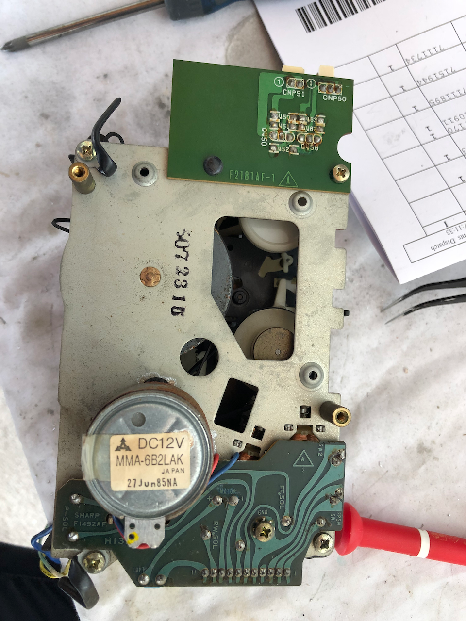
These pictures are taken from the 2nd MZ-2500 I own and comparing with the first, this machine was one of the first to come off the production line. Many manual corrections on the motherboard and additions to the tape drive, such as the F2181AF-1 card including point to point wires across the control circuits show it to be a first production or pre-production unit.
Top view of the first MZ-2500 cassette drive.
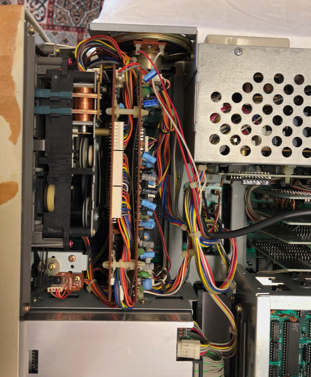
Side view of the second MZ-2500 cassette drive showing the circuit boards stacked on each other. Note the rust on the motor, this machine spent it’s days by the seaside I’m guessing!
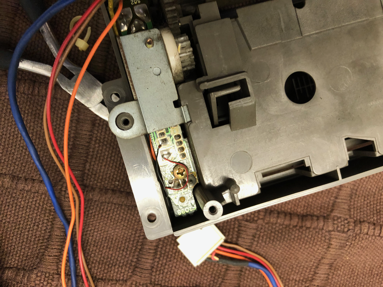
An important point during disassembly, the electret microphone is below the cassette draw damper and control board, you need to desolder the two fine wires before disassembly else you risk damaging it.
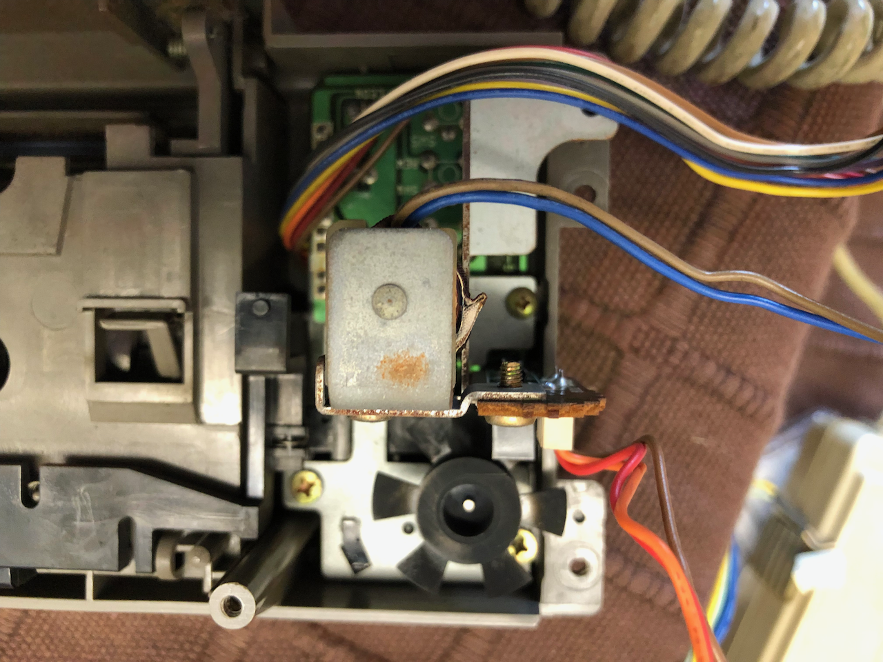
The tape counter control circuit, this is important as it informs the microcontroller that the tape is turning. If no signal is sent it assumes a tape jam and stops the motor and disengages the solenoids.
The partly diassembled mechanism of the 2nd MZ-2500, you cant see the cracks but one exists on the clutch and some plastic c-clip equivalents which keep the cogs/wheels in place.
First level circuit board, similar to the MZ-2000 control board but sited on top of the mechanism. On this one there is additional wiring and components not seen on the first leading me to believe this was a first or pre-production unit.
The motor and rear side of the cassette mechanism before disassembly. Note the additional F2181AF-1 board which doesnt appear on the 1st MZ-2500 or the MZ-2000. Note the rust on the motor casing but underneath rust is prevalent on the flywheel and other metalwork.
The finished main unit, all cleaned with rust prevention and capacitor replacement. I clean up all the wires and connectors as well as generally there is a black oily gunge over everything, a simple wipe with a tissue will evidence this.
Side view during reassembly.
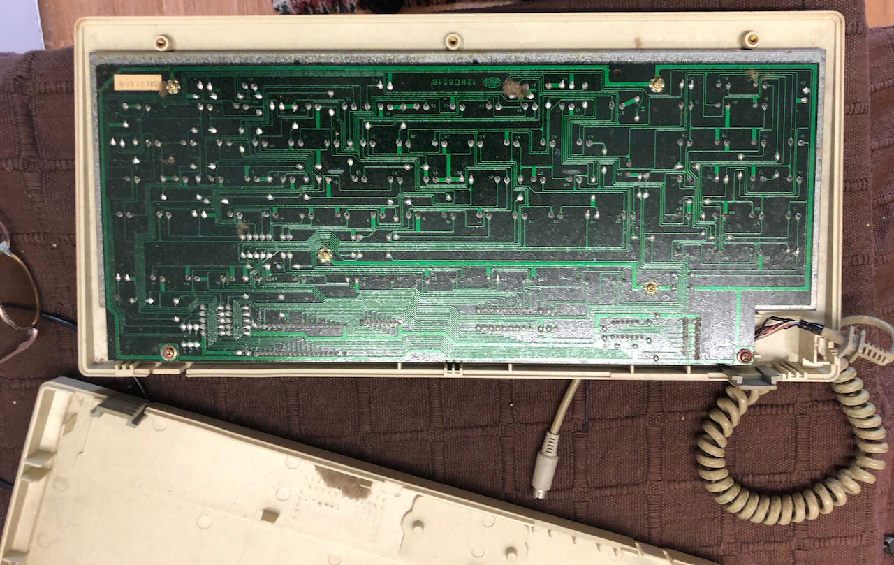
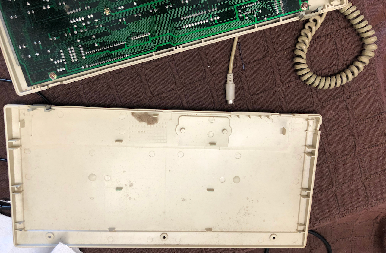
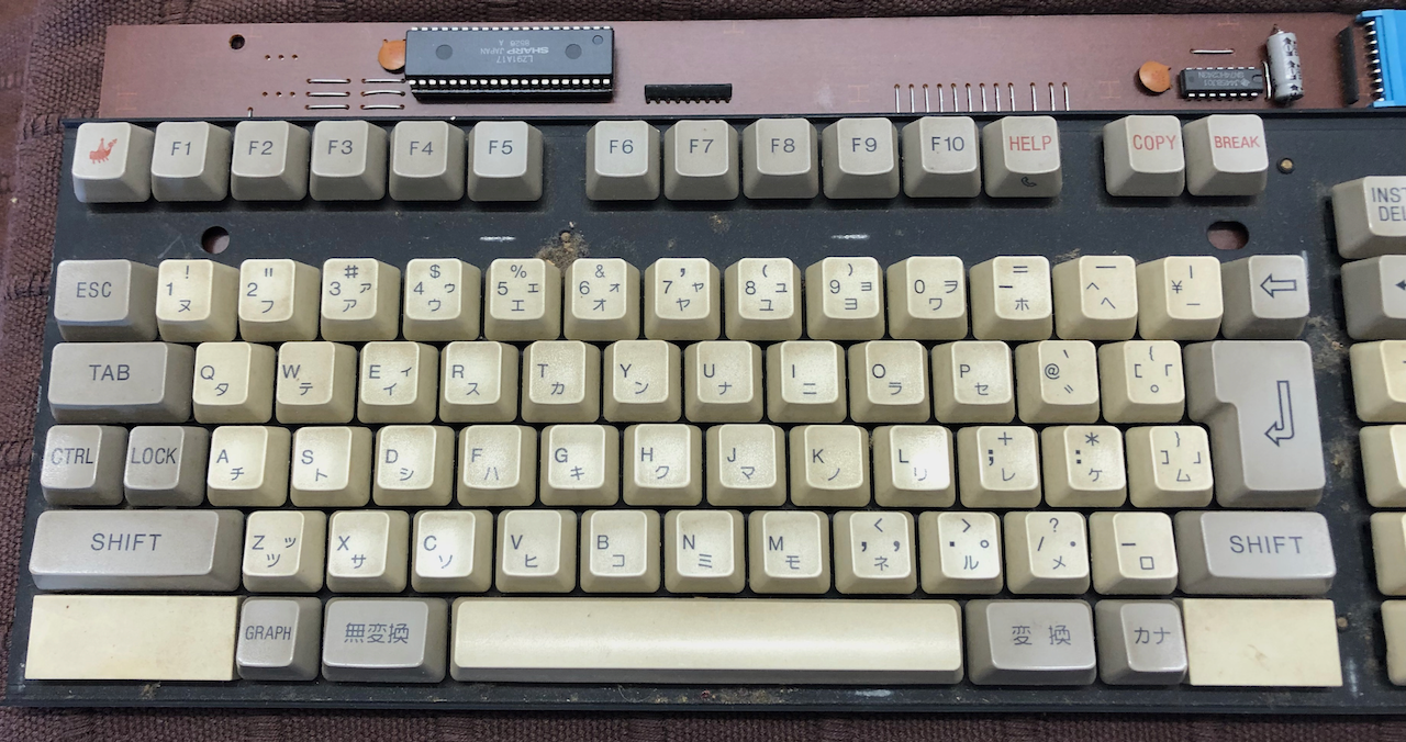
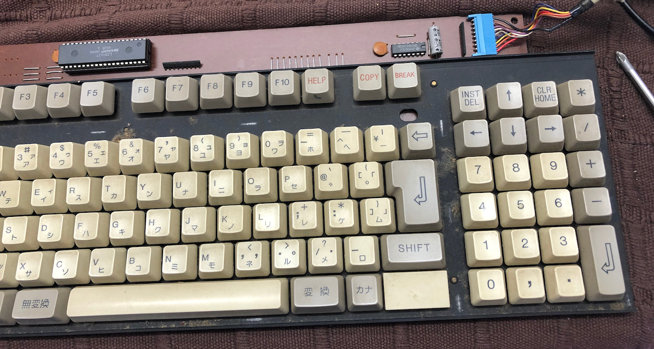
The photos below show the keyboard just after disassembly.
In order to test the various modes of the machine I made cassettes using the TZFS extensions I’ve recently added which allow reading/creating all Sharp MZ tape formats on an MZ-700 or MZ-80A tape deck.
To create the floppy disks I used Kryoflux with the following parameters:
dtc -d0 -dd1 -wv1 -w -fsuper\ mz\ demo\ 1_d88 -e79
It is necessary to convert the D88 format image to Kryoflux raw stream image format before writing to floppy.
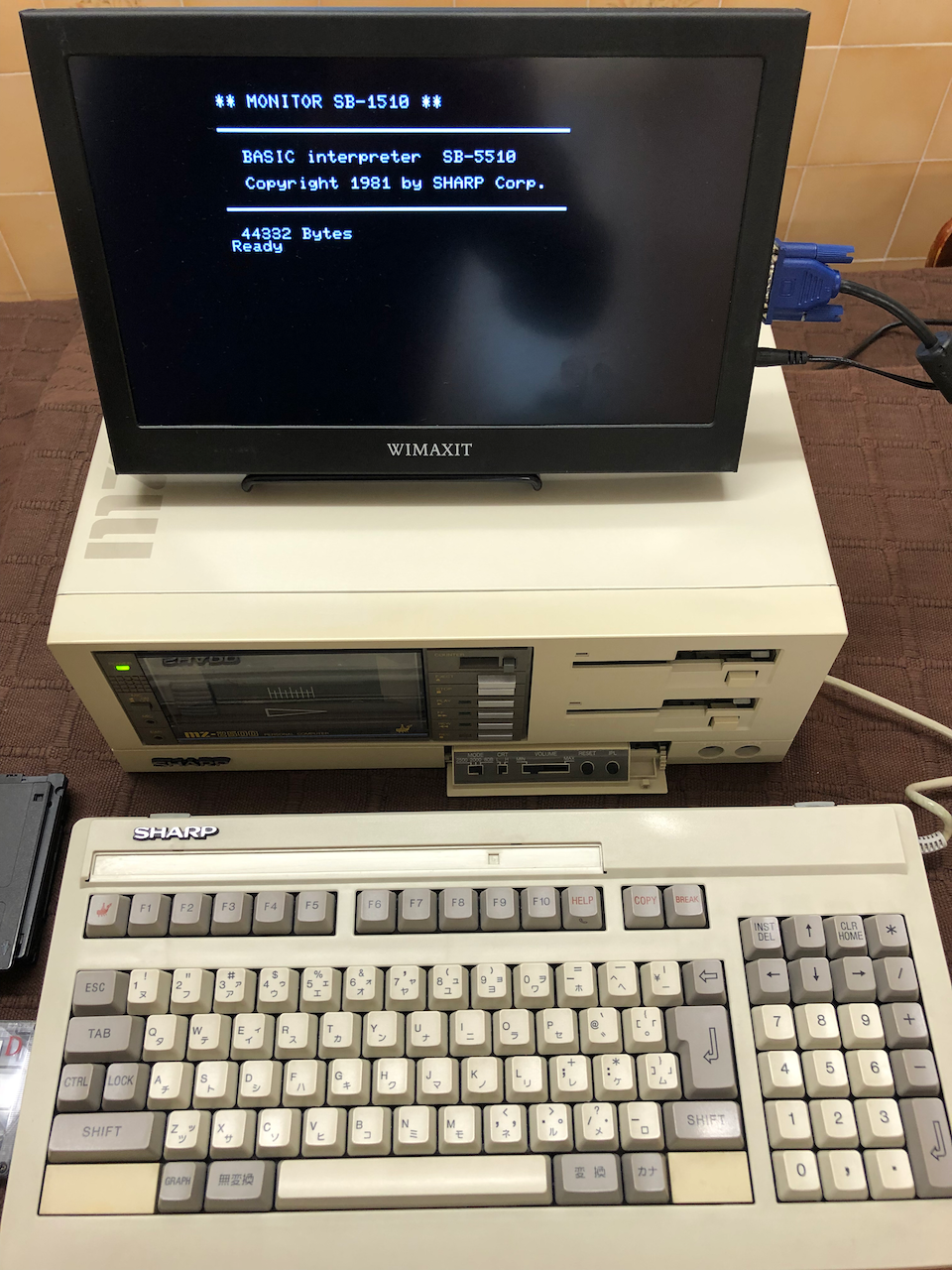
MZ-80B Mode - boot BASIC SB-5510 from tape/CMT unit.
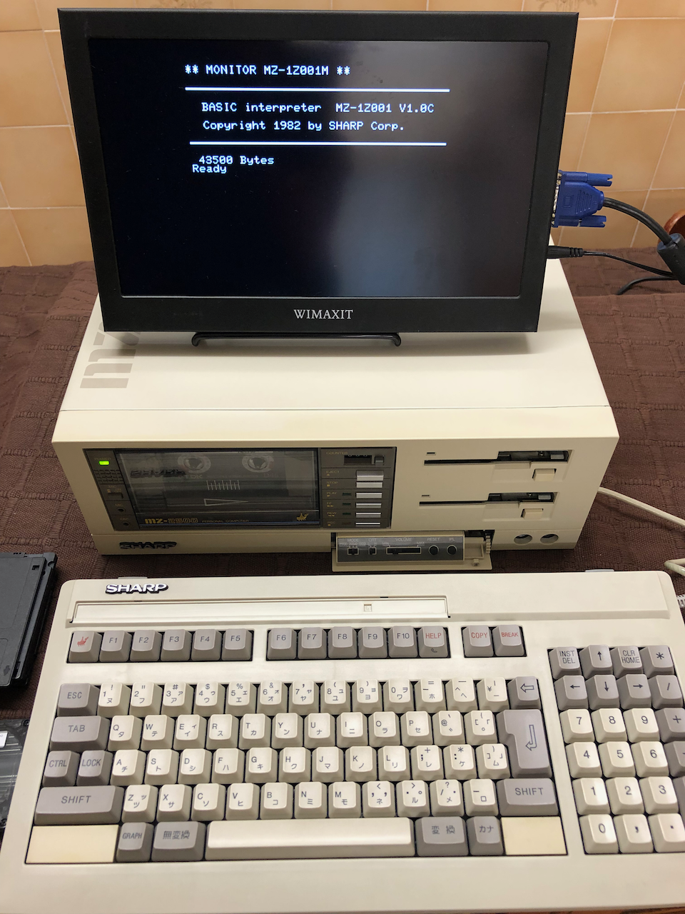
MZ-2000 Mode - boot BASIC MZ-1Z001 from tape/CMT unit.
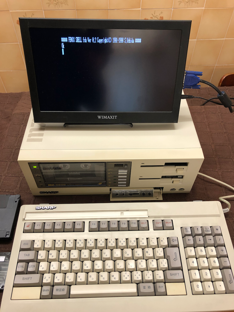
MZ-2500 mode - boot FENICS from floppy disk.
MZ-2500 mode - boot BASIC M25 from floppy disk.
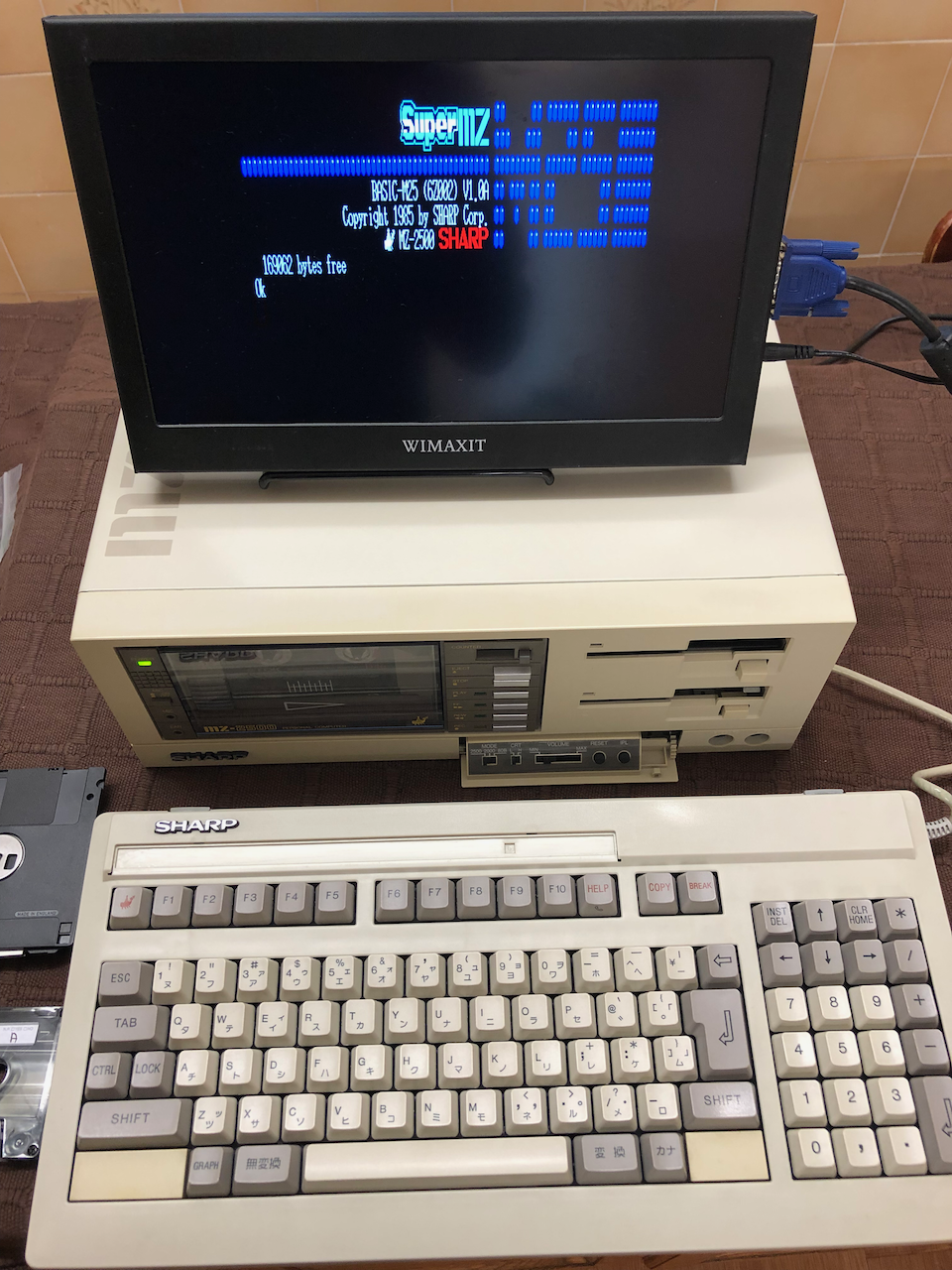
MZ-2500 mode - boot Super MZ Demo from floppy disk. (see video for demo running).

MZ-2500 mode - boot Xevious from floppy disk.
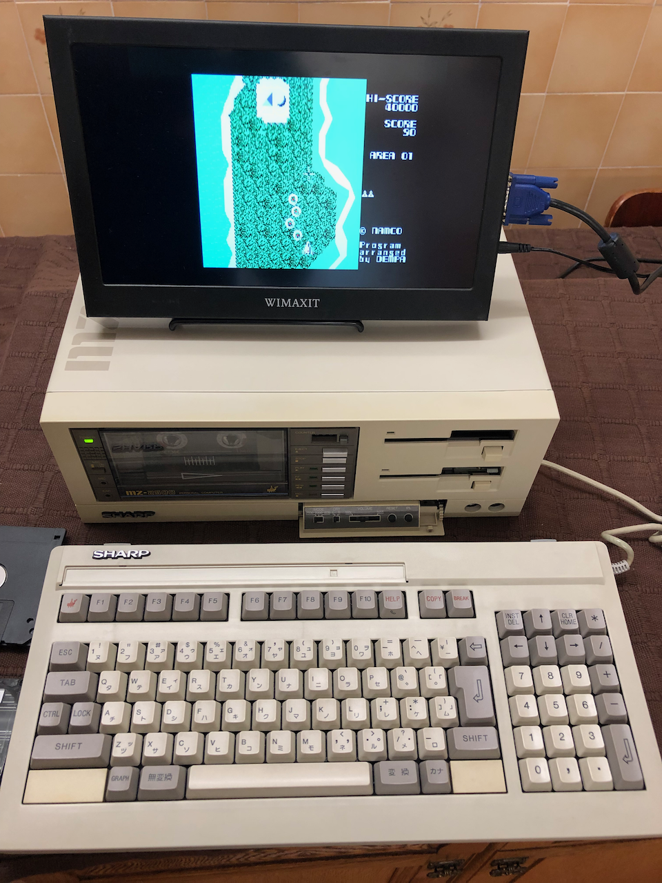
MZ-2500 Demo movie running the SuperMZ Demo Program
This machine I believe was stored for a long time probably in a shop hence the packing tape which was probably a sales leaflet banner across the front. It came with all the original manuals, a Japanese monitor video cable, keyboard overlays and stands, power cable and 2 of the 4 original disks, the missing ones would have been the BASIC M25 and BASIC S25.
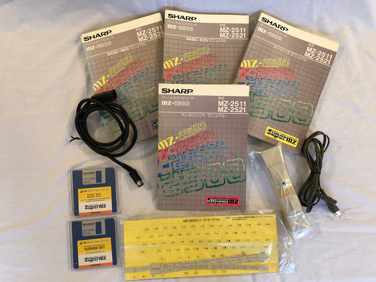
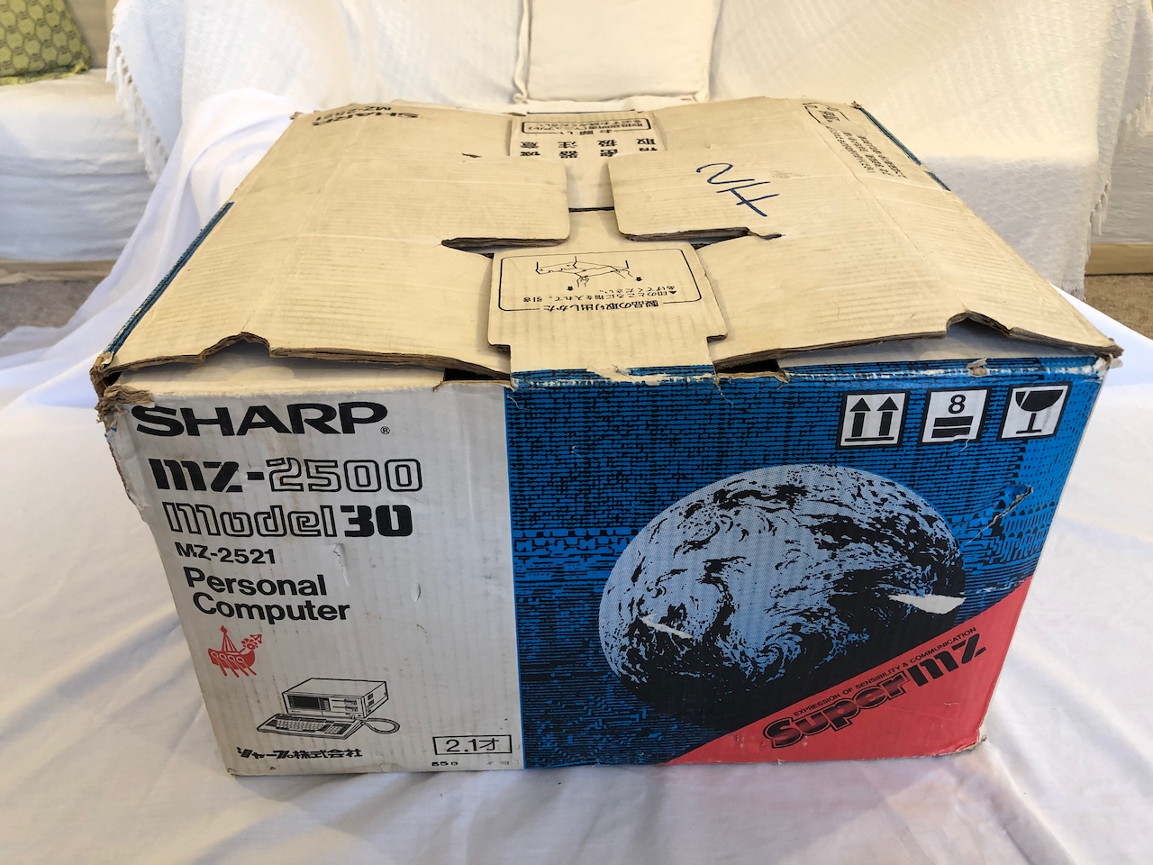
The machine also has its original packaging, the top layer containing the keyboard, manuals and cables and the bottom layer the machine itself.
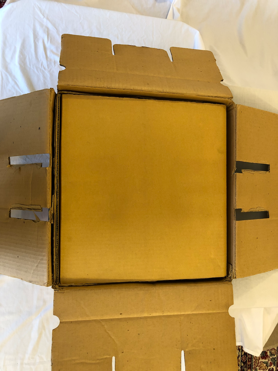
The original box, some luck person on floor 2F I guess use this machine back in the 80’s/90’s.
Next Steps
It was always the intention to sell one of the machines if I could get both working, the first machine is perfect and is more a collectors item, the 2nd has a working motherboard and suitable for testing and development projects but not really for sale other than 'junk'! My thinking is thus to sell the first machine for the right price, I prefer to keep it for myself but if a collector is interested then I'm willing to part with it. That being said, it is dependent on getting the 2nd machine to a useable state, if this is not achievable then I will keep the first otherwise it means buying a third MZ-2500 from Japan (when they come up for auction) and taking another risk that it will work. Watch this space as I will add the 2nd machine renovation details in due course.
UPDATE: Famous Last Words, I ended up buying 2 more MZ-2500's as the 2nd unit mentioned above was unserviceable junk! I bought 2 as there was a period when a few came up and the experience I garnered above showing some were junk I increased the possibility of ending up with a working machine by buying 2!!! Costly, you bet! Well, I lucked out, the 3rd and 4th machine, albeit not show model condition, were both serviceable. One cassette drive was not serviceable but I was fortunate that a Japanese collector I sold a board to sourced and sent me a working unit and a very nice memory expansion board, thank-you Sun Saito! A bit of hard work replacing all the capacitors, stripping the cassette decks to clean and grease, replace belts and pinch rollers etc. The hardest part was what felt like 100 capacitors on the 3 stacked levels of the cassette drive mechanism. Job done, two working machines and one came with original packaging so this one I will put up for sale and keep the 4th. In hindsight I should have kept the 1st machine, it would have cost me less and I would have a perfect example but C'est la vie!
Credits
Licenses
The Gnu Public License v3
The source files are distributed in the hope that it will be useful, but WITHOUT ANY WARRANTY; without even the implied warranty of MERCHANTABILITY or FITNESS FOR A PARTICULAR PURPOSE. See the GNU General Public License for more details.
You should have received a copy of the GNU General Public License along with this program. If not, see http://www.gnu.org/licenses/.