 SharpKey Multi-HID Interface User Manual
The SharpKey
The name SharpKey is derived from
Sharp Keyboard Interface, as it is based on the original mz25key Sharp MZ-2500/MZ-2800 PS/2 Keyboard Interface.
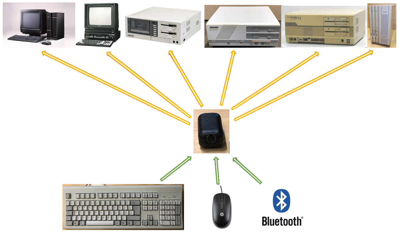
The SharpKey Multi-HID Interface is a device which enables connection of Keyboards and Mice, via PS/2 or Bluetooth, to vintage Sharp and NEC computers. It is
housed in a small KM-24 black or light-grey casing to match the host console colour and takes up minimal additional space. It has two external ports, one for a PS/2 keyboard or mouse and the second
for a cable to connect with the host keyboard or mouse input socket. If bluetooth is used, the PS/2 port is not used and only a host cable from the host port is required.
In use the SharpKey takes power from the host, adding little extra overhead to the host computers power supply. It typically consumes a 30mA when active in interface mode rising to 150mA if the IoT web interface is enabled. Peak instantaneous startup current for WiFi can be 250mA.
This section describes the ports, interfaces, buttons and LEDs of the SharpKey.
Ports
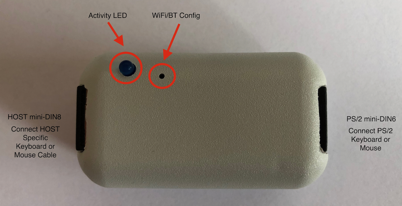
The SharpKey is equipped with two mini-DIN female ports, an LED and a configuration switch for enabling the on-board WiFi IoT web interface and the Bluetooth device Pairing. The image
below shows the locations.
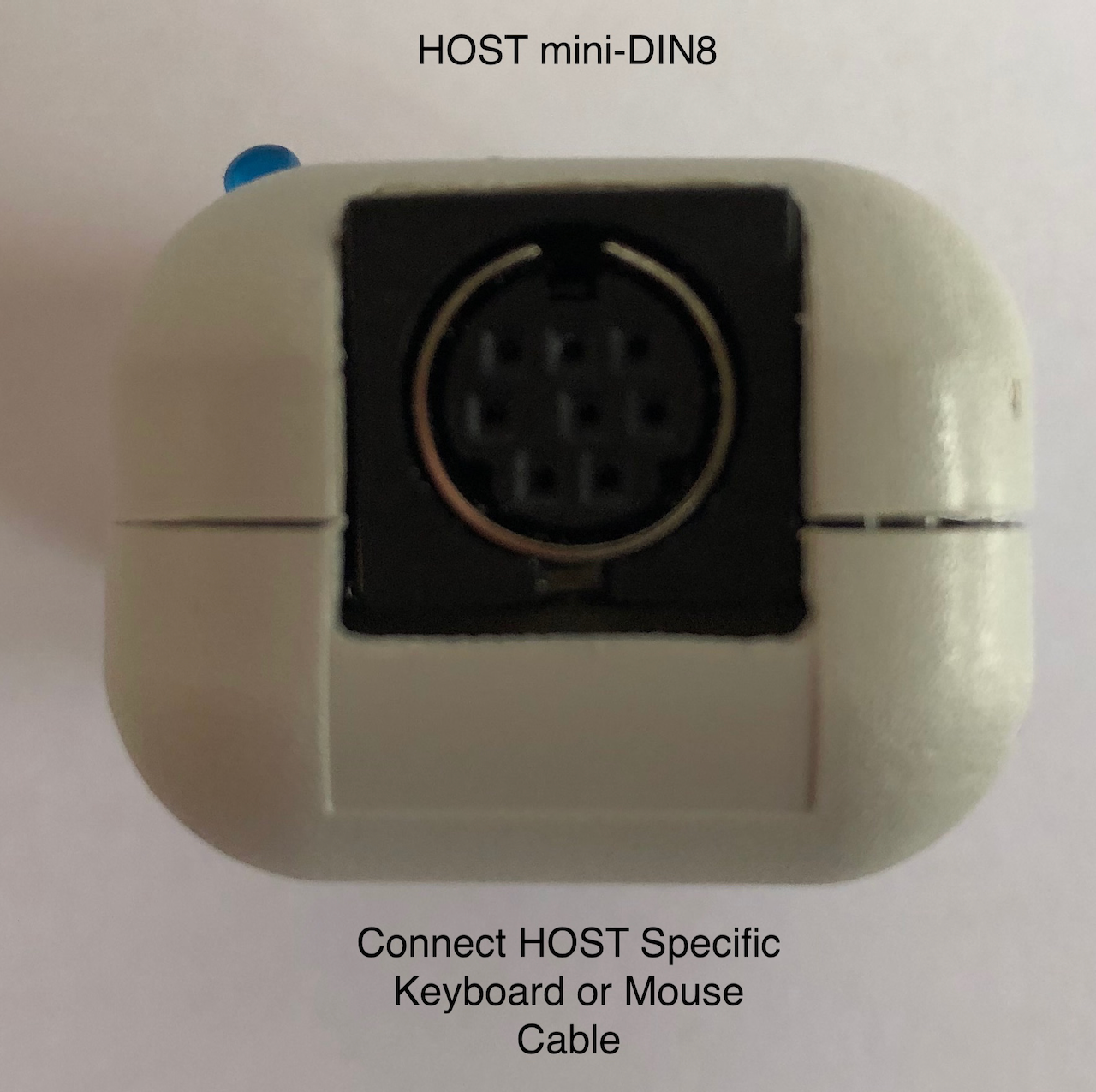
On the left is the HOST connector, this is an 8pin mini-DIN female socket into which a HOST specific cable is plugged. The cable interfaces the SharpKey to either a mouse or keyboard port
on a particular host, ie. Sharp MZ-2800.
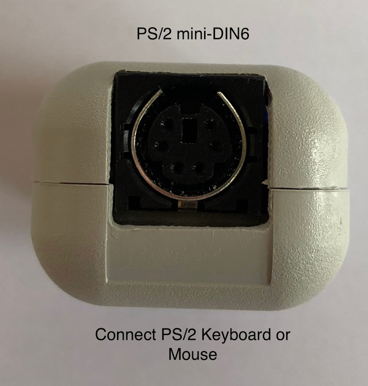
On the right is the PS/2 connector, this is a 6pin mini-DIN female socket into which a PS/2 keyboard or PS/2 mouse is plugged. This socket is hot-swappable so it is possible to unplug a
device and re-insert it whilst the interface is powered on. Plugging a different device of the same type is possible but changing from a keyboard to a mouse/vis-a-viz is not possible as it
would require the HOST cable to be changed as well (ie. if the HOST side is connected to the keyboard input of a Sharp X68000 and the PS2 side to a PS/2 Keyboard, you would need to change the HOST
side to a X68000 mouse cable if you wanted to connect a PS/2 Mouse).
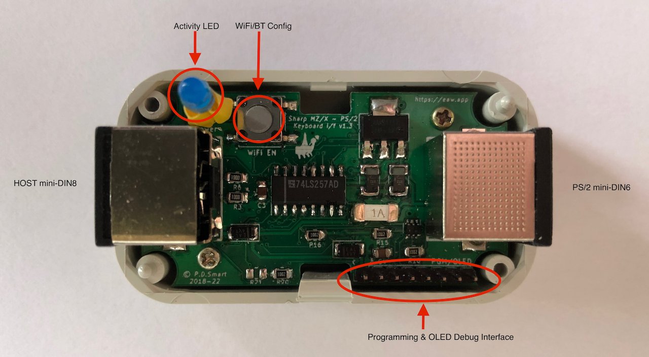
Internally, there is an 8pin 2mm header connector, this is used when OTA Firmware upgrade fails (ie. bricked) or for development and debugging of new features. See the technical documentation for
more information on this connector and its use.
LEDs
The Blue Activity LED is used to indicate device operation and warn of errors or device status.
During normal operation, the Activity LED lights up for a second when the interface is powered on and then the LED powers off. If there is no PS/2 device connected, the LED will light permanently
until a PS/2 device is connected (or Bluetooth enabled and a device pairs with the SharpKey). During keyboard activity, the LED will pulse on each key press. During mouse activity, the LED will
only light up if the 'third wheel button' is pressed and the mouse enters configuration mode.
| LED State |
Occurrence |
Description |
| On |
During power up |
Lights for 1 second then turns off. This indicates normal power up and initialisation successful. |
| |
Normal use |
PS/2 Keyboard or mouse not connected, Bluetooth device not paired. |
| Off |
During power up |
Device failure. |
| |
Normal use |
Device running normally. |
| Pulsing |
Normal use |
LED lights briefly on each keyboard key pressed. |
| |
WiFi Selection |
LED pulses 1 flash per 0.5 seconds when the WiFi key is being pressed for more than 2 seconds and the SharpKey indicates configured WiFi Client/Access Point mode selected. |
| |
|
LED Pulses 1 flash per 0.25 seconds when the WiFi key is being pressed for more than 5 seconds and the SharpKey indicates default parameter Access Point mode selected. |
| |
Bluetooth Pairing |
LED Pulses 1 flash per 0.125 seconds when the WiFi key is being pressed for more than 10 seconds and Bluetooth Pairing mode selected. |
| |
NVS Reset |
LED Pulses 1 long flash per second when the WiFi key is being pressed for more than 15 seconds and NVS Reset is selected. |
Switches
The WiFi/Bluetooth configuration switch is located within the SharpKey casing and accessed via a pin-hole on the casing top, next to the LED. A non-conducting rod needs to be used, inserting
it into the pin-hole and depressing the internal switch.
The length of time the switch is depressed indicates the feature the user wishes to access.
| Time Switch Depressed |
LED |
Feature |
| 1 second |
Off. |
Cancel any selected feature, ie. WiFi mode or Bluetooth pairing. |
| 2 key presses in 1 second |
SharpKey reboots and LED will light until a key is pressed or mouse moved. |
Reboot SharpKey. Used if you need to reboot the SharpKey, for example, changing from PS/2 to Bluetooth after disconnecting PS/2 device. |
| 2 - 4 seconds |
Flashes 2 times per second. |
Select configured WiFi mode, Access Point or Client. |
| 5 - 9 seconds |
Flashes 4 times per second. |
Select default parameter WiFi Access Point mode. |
| 10 - 14 seconds |
Flashes 8 times per second. |
Select Bluetooth Pairing mode. |
| 15 - 19 seconds |
Flashes one long pulse per second. |
Select NVS Reset mode (clear all settings and restore to factory mode). |
See the relevant section for more information on accessing and using the different features.
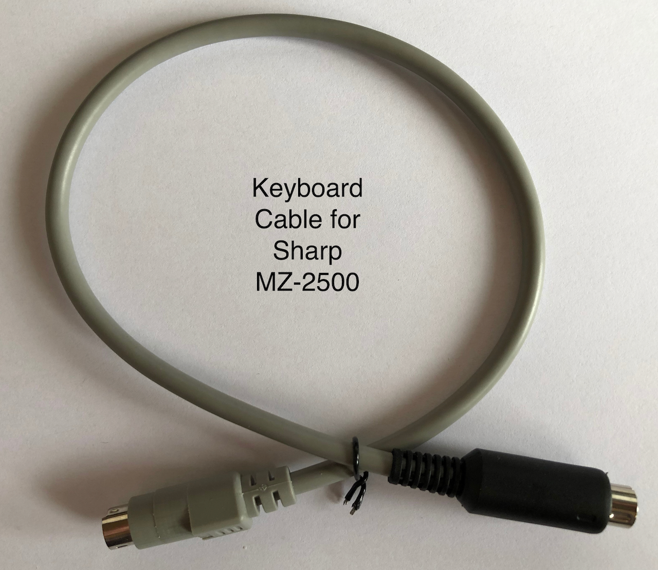
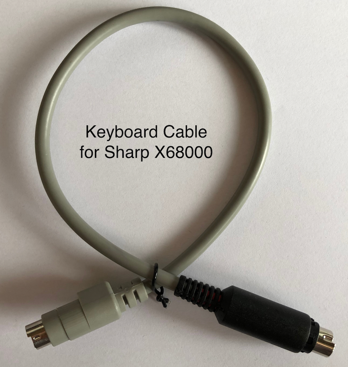
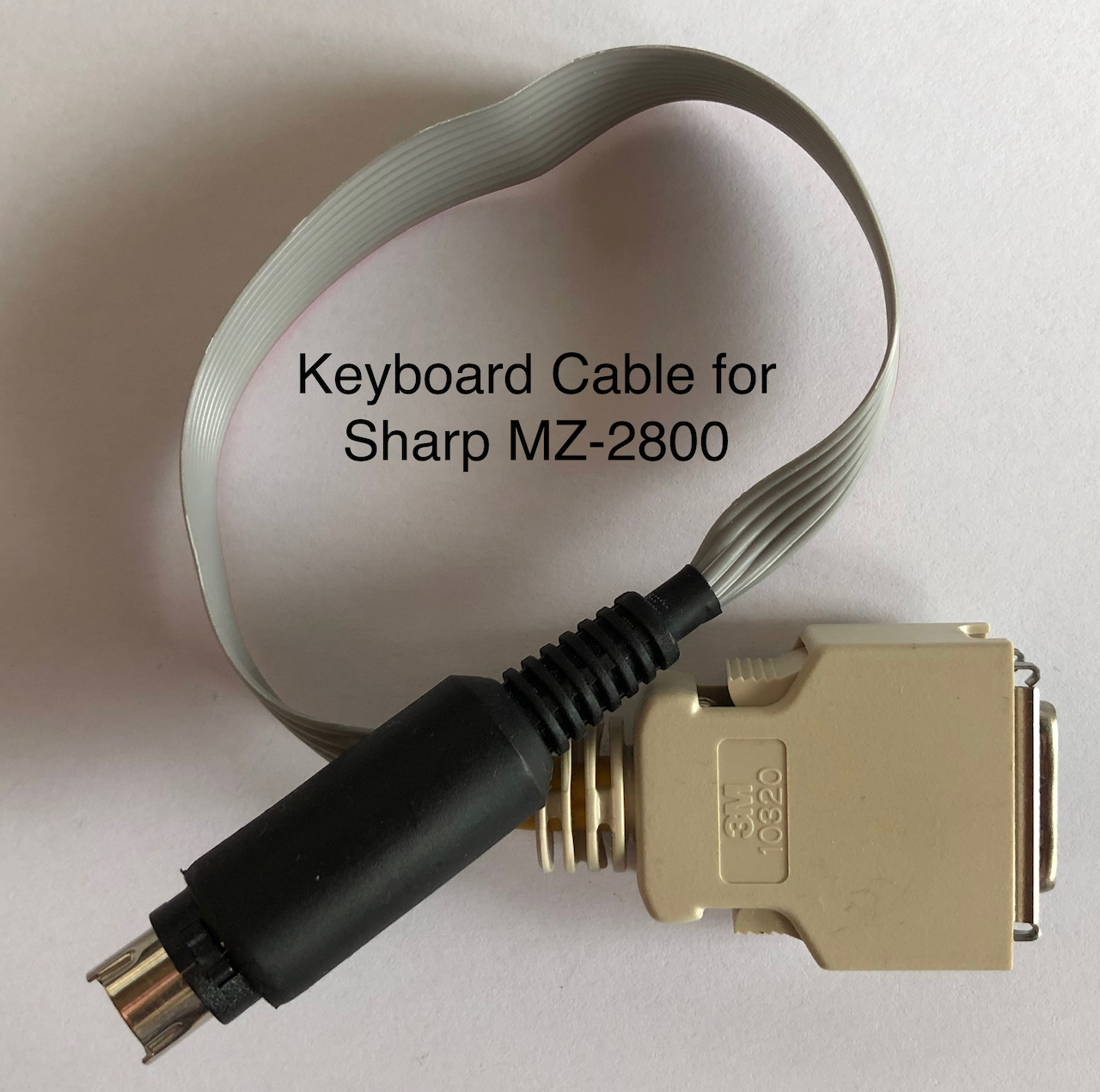
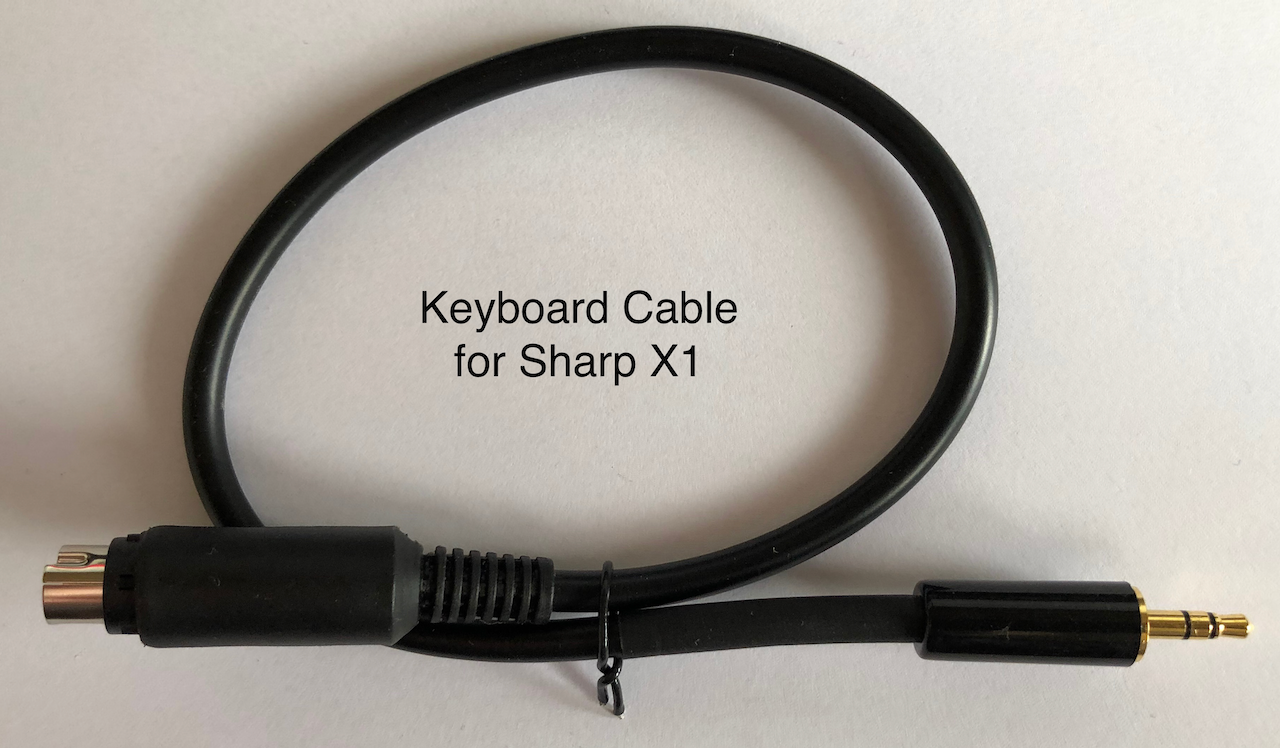
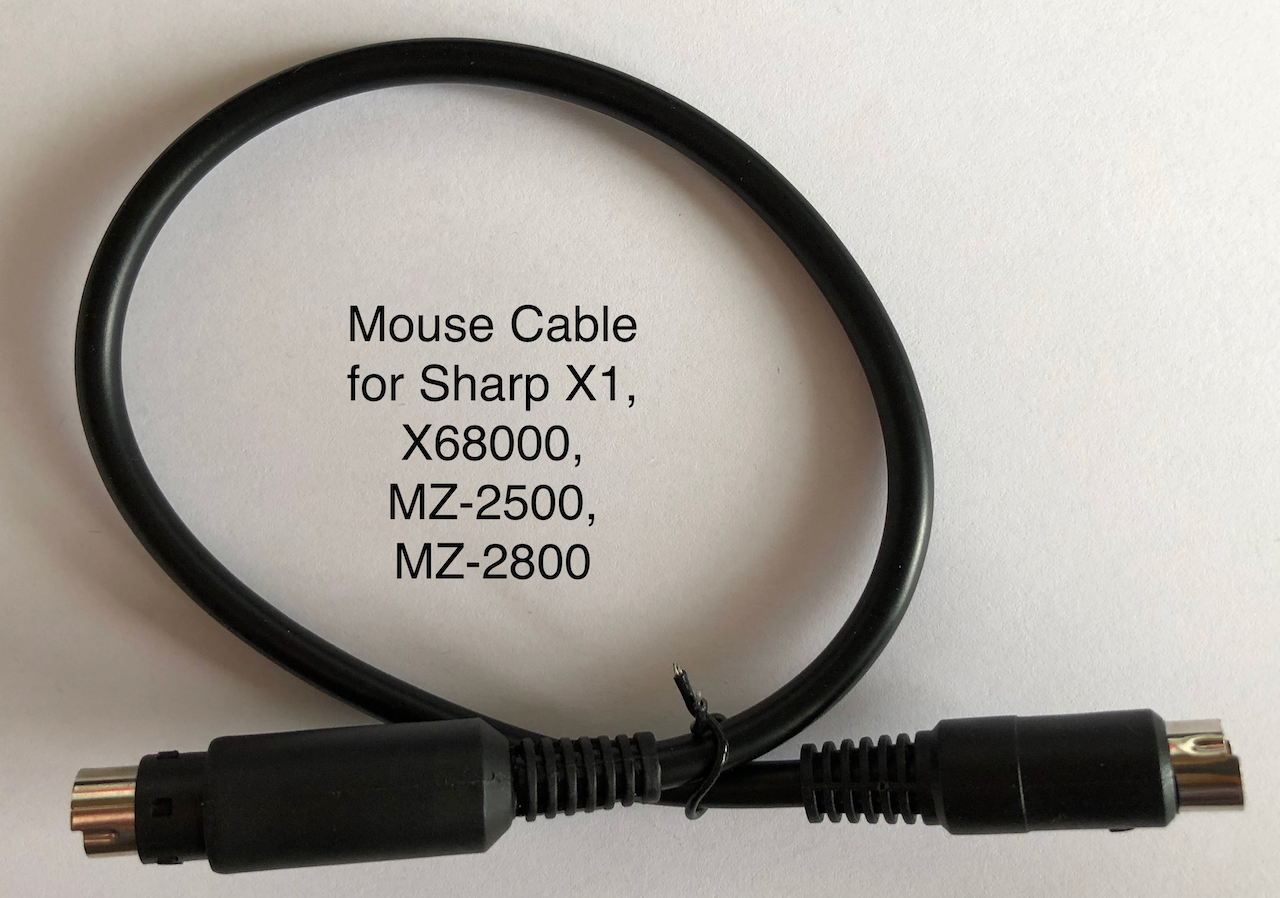
Cables
Each host machine has different electrical and mechanical specifications for its keyboard and mouse inputs. The SharpKey is able to manage the electrical and protocol requirements but
the mechanical requirement must be met with a physical cable.
This means each host machine keyboard and mouse input port requires a unique cable from the SharpKey into the host keyboard or mouse port. On Sharp machines, the mouse port is common so
only one cable is required to connect the SharpKey to any Sharp mouse port. The different cables can be seen below.
Each cable has an 8pin mini-DIN connector attached (the MZ-2500 has 2 so either side connector can be used) which plugs into the SharpKey. The opposite end of the cable plugs into the host keyboard or mouse
port.
Connecting the SharpKey
Connecting the SharpKey is simply a matter of obtaining the correct cable for your host machine, either keyboard or mouse, plugging the 8pin mini-din end into the SharpKey and the opposite
end into your host machine keyboard or mouse port.
If you intend to use a PS/2 Keyboard or PS/2 mouse, insert the keyboard/mouse 6pin mini-din connector into the opposite end of the SharpKey. If you are intending to use Bluetooth then no
connection needs to be made with the PS/2 port on the SharpKey.
NB. Bluetooth will only be enabled when no PS/2 device is connected.
Once the cables have been connected, power on your machine and use the PS/2 keyboard/mouse or Bluetooth keyboard/mouse as normal. If any keyboard keys do no map correctly to the host
keys, you can use the IoT web interface to add key mappings as required.
NB. Bluetooth devices require pairing and once paired, on power up, may take a few seconds to connect. When using Bluetooth at power up, wake the bluetooth devices up by repeatedly hitting the shift key or shaking
the mouse, this is necessary as the device will be in sleep mode and the SharpKey wont be able to connect.
Bluetooth Pairing
In addition to PS/2 HID devices, Bluetooth wireless devices can also be connected to the SharpKey.
In order to use Bluetooth,
No PS/2 device should be connected to the SharpKey. If the SharpKey detects a PS/2 device during startup it will not enable Bluetooth. The Bluetooth transceiver in the ESP32 is
not so powerful so your device needs to be in a 1m range or less (some devices, typically mice, operate over a much longer distance).
On receipt, in
factory default mode or after an
NVS Clear function, the SharpKey will perform a Bluetooth scan looking for nearby devices which are in Pair mode. Simply press the
pairing button on your keyboard or mouse device and within 5-10 seconds it should connect
without requiring a pairing PIN.
Upto 5 additional devices can be paired with the SharpKey (which will operate simultaneously if all 5 devices are connected) can be added by placing the SharpKey into
Pairing Mode. To enter
Pairing Mode press the Wifi/Config Enable switch for 10-15 seconds, as you hold the key
you will notice the Blue LED change pattern:
- 2-5 seconds it will flash twice per second which indicates WiFi Enable Mode is selected if you release the switch.
- 5-10 seconds it will flash 4 time per second indicating Default WiFi Mode is selected if you release the switch.
- 10-15 seconds it will flash 8 times per second indicating Bluetooth Pairing Mode selected if you release the switch.
Release the switch after 10 seconds and the SharpKey will enter pairing mode and connect with any HID devices it finds in Pairing mode. The SharpKey stays in
pairing mode for 60 seconds during which time it will pair with as many HID devices it finds.
Device authentication (PIN entry) has been programmatically disabled for the SharpKey as it has no means to display a pairing PIN. This method generally works well for most BLE and BT Classic devices
but should your device require a PIN which cannot be disabled, after about 10 seconds the Blue LED will start flashing with 3 long pulses, repeated every second. If you see the LED flashing then enter the PIN code '
1234' on your keyboard and press ENTER. If the LED continues
to flash, repeat the PIN entry until it pairs and the LED stops flashing.
On future power cycles of the SharpKey it will be necessary to shake or wake your bluetooth device so that it reconnects. This can be achieved by pressing the
Shift key repeatedly on your keyboard or moving your mouse. If the bluetooth devices isnt woken, the SharpKey wont be able to see
it and connect. It can take 1-10 seconds to reconnect depending on your device and range from the SharpKey (the further the distance the longer it may take due to the ESP32 Bluetooth transceiver not being very powerful).
Accessing the IoT Web Interface
The SharpKey has several preconfigured keyboard maps, factory default set to a UK keyboard layout on all of the supported host machines. Using hotkeys (see below) it is possible to select a different map.
The in-built maps will evolve over time to support more keyboards and these updates will be distributed as a firmware update. Keyboards layouts currently supported are:
- Wyse KB-3926 UK Layout
- Generic OADG109 Japanese Layout
- Sanwa SKB-L1 Japanese Layout
- Perixx Periboard 810 UK Layout
- OMOTON K8508 UK Layout
There exists however an edge case of a key not working or not working the way it should for
an individual user, also other users may find their regional (country) keyboards not working well and these shortcomings needs to be addressed by the user who has more hands on experience.
To this end, the SharpKey can be configured to map any PS/2 code or code combinations into a key sequence expected by the active host. Bluetooth scancodes are internally mapped to PS/2 scancodes
so all keyboard type (PS/2 or Bluetooth) mapping is performed using PS/2 codes.
In order to make changes the SharpKey is equipped with an in-built web server using WiFi technology and can be configured in Access Point mode (you connect your WiFi device to the SharpKey) or Client mode
where the SharpKey uses stored credentials to connect with your home network router.
To access the web interface, the SharpKey needs to enable the wifi Access Point or Client transceiver. This is done via the
WiFi/BT Config switch.
There are two WiFi modes, Access Point and Client:
- Access Point is where the SharpKey acts as a WiFi router and you search via your computer/phone wifi settings for the WiFi network:
sharpkey and connect using the password: sharpkey. The SSID and password can be changed in the configuration but should you forget your changes, pressing the WiFi/BT switch for more than 5 seconds
will force the SharpKey to enter Access Point mode using the aforementioned defaults.
- Client mode is where the SharpKey connects to your home network, details of which must be pre-entered into the SharpKey via the Access Point mode. Once set, each time the SharpKey enters WiFi mode
it will automatically try to connect to your router, using DHCP (your router allocates it an address) or with a fixed address you provide.
The steps for accessing each of the modes can be seen in the table below.
| Mode |
How to Access |
Description |
Access Point mode.
Initial setup or by forcing default mode. |
Initial factory setup, pressing the WiFi switch for 5-10 seconds will enter WiFi Access Point mode. If a bad configuration has been made or you have a network change, press the WiFi switch for 5-10 seconds to load default parameters and enter Access Point mode. |
Search on your computer or phone WiFi settings menu for the network:sharpkey. Connect with this network and enter the password:sharpkey. After successful connection, open a web browser and enter in the address bar: http://192.168.4.1 - you will now be able to access the SharpKey and configure the WiFi via WiFi Manager. |
| Access Point mode. |
Once the SharpKey has been configured and you selected AP Mode in the WiFi Manager, pressing the WiFi switch for 2-5 seconds will enter Access Point mode. |
This mode is where you have selected Access Point mode via the WiFi Manager menu in the browser configuration. You can change the network name (SSID), password and IP address range to suit your requirements. In this mode you will always connect to the SharpKey by joining its network in the WiFi settings menu of your computer or phone and access the configuration web page using the settings you provided. |
| Client (also called Station) mode. |
Once the SharpKey has been configured and you selected Client Mode in the WiFi Manager, pressing the WiFi switch for 2-5 seconds will enter Client mode. |
This mode allows the SharpKey to connect with your network via WiFi login to your router. During the initial connection in Access Point mode, under the WiFi Manager menu, select and setup Client mode with your router credentials. Once configured, everytime you enable WiFi the SharpKey will connect to your router and be accessible by an allocated IP address on your network or a fixed IP address you entered in the WiFi Manager menu. |
After pressing the WiFi configuration switch for the required amount of time the device will reboot and enter the requested WiFi mode. The blue led will light and if it remains lit then an error has occurred. If it briefly flashes several times then the desired WiFi configuration has been setup and established.
If all is successful and you have either joined the Access Point network or the SharpKey has connected to your network, opening a browser and entering the correct IP address, (ie. http://192.168.4.1 for the initial Access Point mode) will see the status screen below.
The correct IP address is the one you configured in WiFi Manager, or in the case of Client Mode with DHCP enabled, the one allocated by your router which you can find by looking at the admin page of your router.
A visual indication of the SharpKey connecting to your
Configuring Access Point Mode
The SharpKey factory state automatically starts in Access Point mode when WiFi is enabled. WiFi is enabled by pressing the WiFi/BT Config switch for 2-5 seconds. Once the device is configured, if the device cannot be accessed (for example, due to network change), pressing the WiFi/BT Config switch for 5-10 seconds will automatically enter Access Point mode with default parameters.
The default parameters in unconfigured Access Point mode are below.
| Parameter |
Value |
| SSID (network name) |
sharpkey |
| Password |
sharpkey |
| Access Point IP address |
192.168.4.1 |
| Router address |
192.168.4.1 |
| DHCP assigned IP range |
192.168.4.2 - 192.168.4.254 |
After setting the SharpKey into WiFi mode, access the WiFi menu of your computer or phone and select the
sharpkey network. Enter the password
sharpkey, your computer or phone will now join the SharpKey network and you can access it's web interface.
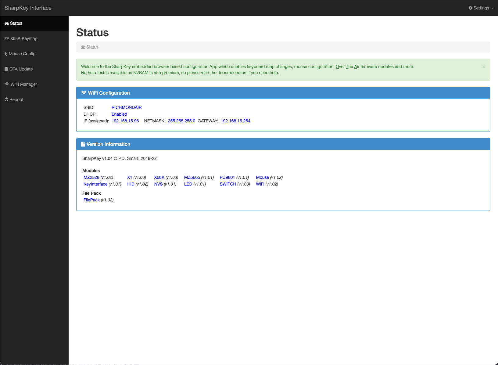
Enter the URL http://192.168.4.1 into a web browser and you will be presented with the status screen:
The status screen shows 2 panels, a
WiFi Configuration panel which shows the active WiFi configuration being used by the SharpKey and a
Version Information panel which shows the firmware modules installed along with their version number and the disk filesystem version. This information can be used
for feature verification or fault tracking/raising a support ticket and also to view versions to see if an update pack offers newer software or fixes.
In the left side of the screen, called the sidebar menu, are the possible options available to view or configure in the web interface. This document details each of the options in more detail further down.
Click on the
WiFi Manager option in the left sidebar menu. This will start the WiFi Manager configuration screen which will appear like:
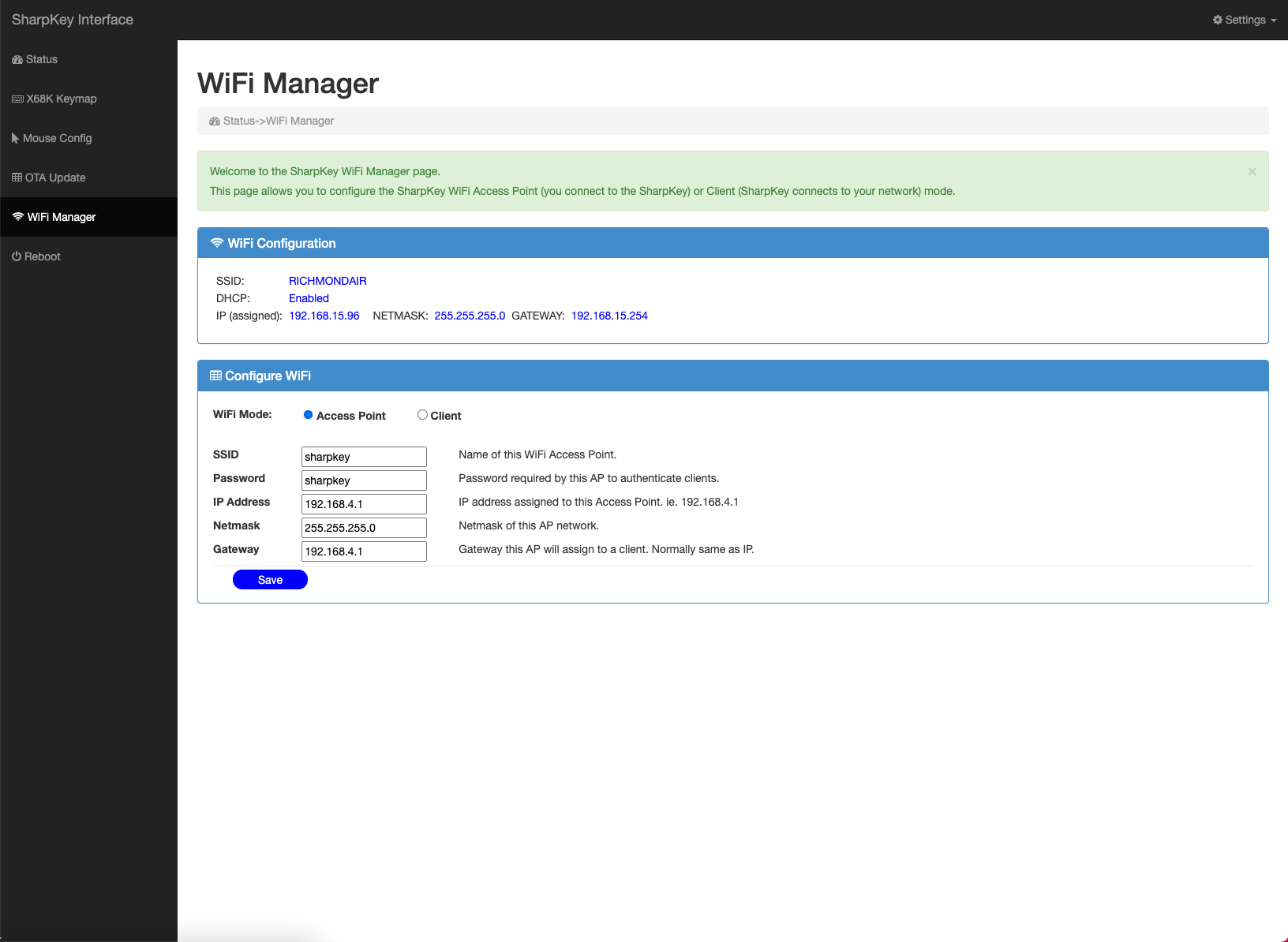
You now have a choice, configure the SharpKey as an Access Point or as a Client. Access Point means the SharpKey provides the WiFi network and your computer/phone needs to connect with it via the WiFi settings menu. Client mode means you enter details of your home network and the SharpKey will automatically connect to your home network and your computer or phone
will see it as a device on your network.
If you decide to use Access Point mode, you can leave it configured with the defaults, or change them with the Configure WiFi panel below.
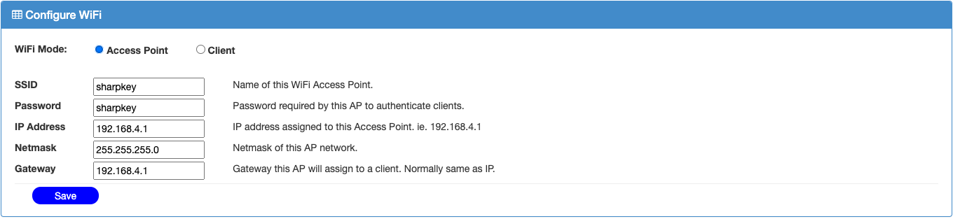
The options for the Access Point mode in the Configure WiFi panel are:
| Option |
Description |
| WiFi Mode |
Select the type of mode required, in this instance click on Access Point. |
| SSID |
This is the network name you will see on your computer or phone when you go to the Wifi settings menu and scan for available networks. Either leave it as default or change to a meaningful name. |
| Password |
This is the password your computer or phone will request when you choose to join the network identified by SSID. |
| IP Address |
This is the IP address range the SharpKey will use for its DHCP server which allocates any connecting clients requesting an address. This value should end with a .1 which is assigned to the SharpKey and the DHCP server will allocate addresses xxx.xxx.xxx.2 - 254 to a connecting client. |
| Netmask |
This is the network mask used for filtering and masking IP addresses. Unless you are network savvy, always set this address to 255.255.255.0. |
| Gateway |
This is the gateway a computer or phone needs to route network requests. This should be the same as IP Address as the SharpKey doesnt perform routing. |
Once you have entered the required settings, press on
Save and the data will be validated. If the data is correct, a message will be displayed in green advising you all is ok and to press Reboot. If the message is in red, take note of the error and correct accordingly, pressing
Save once the error has been fixed.
After a successful save, press reboot and the SharpKey will reboot, immediately entering WiFi mode for data confirmation (ie. you dont need to press the WiFi/BT Config switch again). Just allow a few seconds and then join with the SharpKey network using your computer or phones WiFi settings menu. Once connected to the SharpKey network, open a browser and enter the IP Address you
chose in the
Configure WiFi panel and you will be immediately taken to the SharpKey status menu.
Configuring Client Mode
The SharpKey factory state automatically starts in Access Point mode when WiFi is enabled. Follow the Access Point mode configuration up until you see the SharpKey status screen and follow the instructions below.
Click on the 'WiFi Manager' option in the left sidebar menu. This will start the WiFi Manager configuration screen which will appear like:
You now have a choice, configure the SharpKey as an Access Point, in which case follow the
Configure Access Point Mode instructions, or configure the SharpKey in Client Mode.
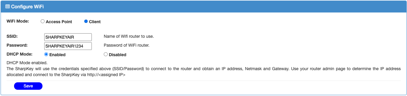
If you decide on Client Mode, click on the
Client radio button and the
Configure WiFi panel will update to request Client parameters. There are two distinct Client mode's of operation, either
DHCP Enabled where the router provides all network connection information or
DHCP Disabled where you manually specify network parameters.
The initial parameters requested in the
Configure WiFi panel appear below, which is the same for DHCP Enabled or Disabled mode.
| Option |
Description |
| WiFi Mode |
Select the type of mode required, in this instance click on Client. |
| SSID |
This is the network name you want the SharpKey to join with in order to establish a connection with your home network. |
| Password |
This is the password the SharpKey will provide to your router to authenticate itself and establish a connection. |
| DHCP Mode |
This specifies wether you want your router to provide all network information (Enabled) or you will manually provide it (Disabled). |
The panel will appear as indicated below:
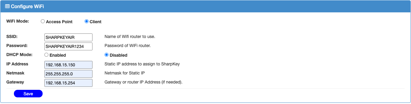
Should you decide to use DHCP Disabled mode, additional parameters are requested in the Configure WiFi panel:
| Option |
Description |
| IP Address |
This is the address the SharpKey will use for itself on your home network. You will connect to the SharpKey using this address in your browser, ie. http://<IP Address>. |
| Netmask |
This is the filter and masking parameter in order for your SharpKey to occupy parts of a subnet. Unless your network savvy, enter 255.255.255.0 |
| Gateway |
This is the IP address of the device on your network which acts as a gateway to the internet/intranet. The SharpKey is not internet aware so enter the same value as the IP Address above. |
The updated panel will appear as indicated below:
Once you have set the correct mode of operation and entered the requested parameters press
Save and the parameters will be validated and updated. Should the parameters be valid a green success message will appear indicating this and requesting you to press reboot. Should the parameters be invalid, a red message will appear indicating which entry is incorrect, fix it and press
Save again.
After a successful save, press
Reboot on the left side-bar and the SharpKey will reboot. Press the WiFi switch again if you want to enter WiFi mode with the new settings. If the SharpKey fails to join with the network the LED will stay lit otherwise will blink several short pulses to confirm WiFi connection. If the SharpKey fails to enter WiFi mode (ie. cannot connect with your router), the LED will remain lit and after 1 minute
it will reboot. In this situation, press the WiFi/BT Config switch for 5-8 seconds and it will enter WiFi Access Point mode with default settings so you can reconfirm the credentials you entered.
OTA Updates
The SharpKey is equipped with a feature to allow updates to its internal firmware or disk filing system. The firmware or filesystem can be upgraded for newer features or to fix known bugs.
In order to use the OTA Updates feature, access the web interface using the Access Point/Client information above and open a browser to load the initial status page, ie:
Click on the OTA Update option in the left sidebar menu. This will start the OTA Update configuration screen which will appear like:
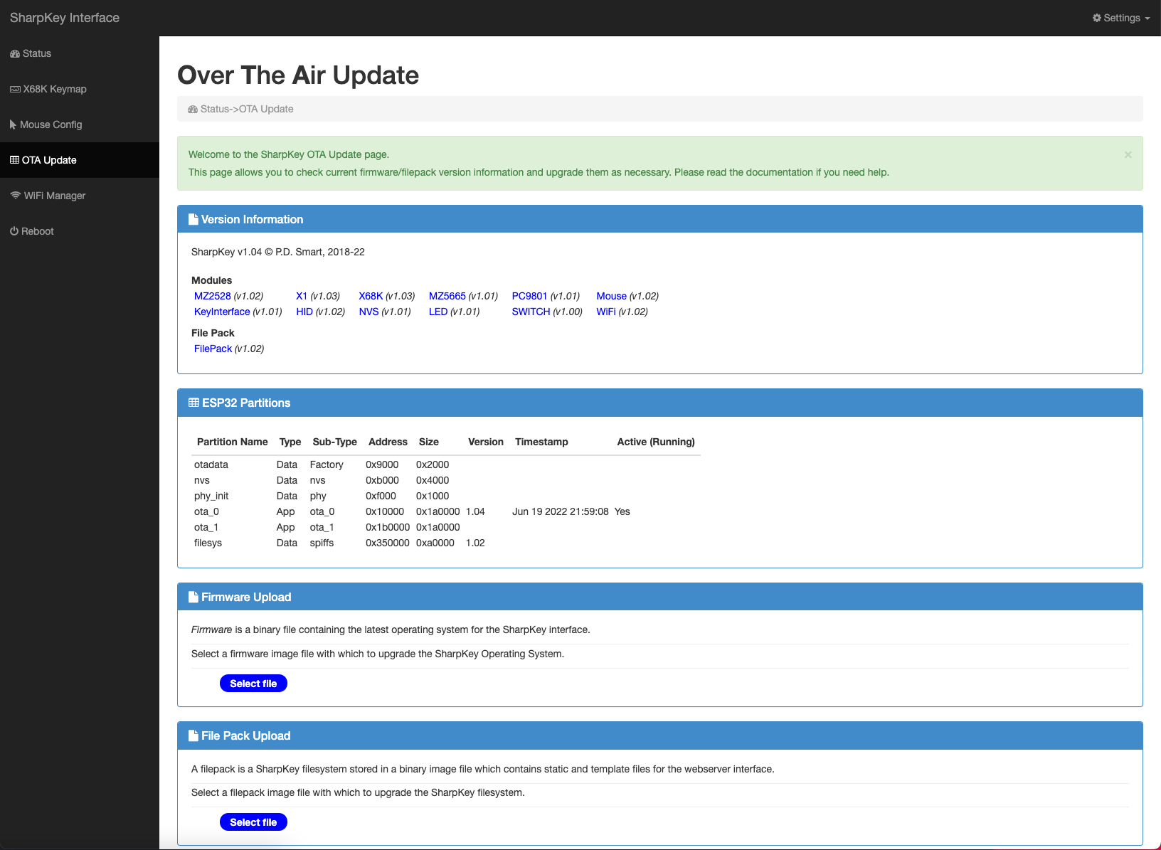
The OTA Update screen shows 4 panels:
- a Version Information panel which shows the firmware modules installed along with their version number and the disk filesystem version. This information can be used
for feature verification or fault tracking/raising a support ticket and also to view versions to see if an update pack offers newer software or fixes.
- an ESP32 Partitions panel which shows the layout of the NVS Flash RAM on the ESP32 SoC which powers the SharpKey. The information of interest is the Partion Names: ota_0, ota_1 and filesys. The SharpKey uses a fault tolerant update system in a round robin method. If the current firmware is running on partition ota_0 then any updates will be placed onto ota_1. After update, should
the SharpKey fail to boot an automatic rollback is performed and the SharpKey will reboot off ota_0. This is not the case for the filesystem filesys, if an update fails then the filesystem may be corrupted and the web interface will fail to work. In this case an external programming probe needs to be connected to the SharpKey in order to reflash the filesystem. This is a rare occurrence and
only happens due to software bugs or power outages.
- a Firmware Upload panel which allows you to select a new firmware file and upload it into the SharpKey.
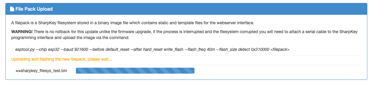
- a File Pack Upload panel which allows you to select a new filesystem image file and upload it into the SharpKey.
In order to upgrade the firmware, click on the
Select file button in the
Firmware Upload panel and choose a stored or downloaded firmware image. Validation will occur before programming so if you choose the wrong image, the SharpKey will refuse to update. Validation will also check the version and block the update if the version chosen is the same as the current firmware. Once selected, the panel will update as follows:
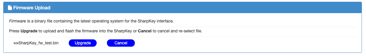
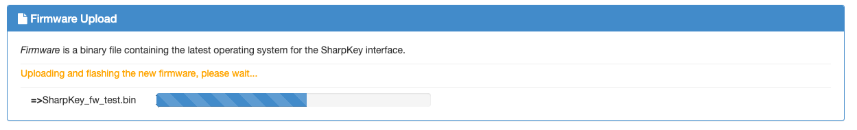
Click on the Upgrade button if you are ready to upload and flash the new firmware into the SharpKey or click Cancel to clear the chosen file. Once you press Upgrade the update procedure will commence, firstly the file will be validated and if valid, file upload will take place and the panel will change showing the status:
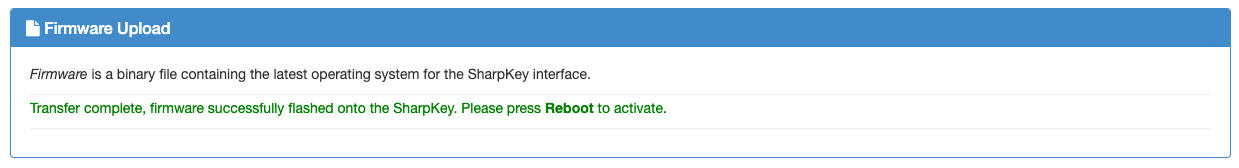
After a successful upload, a green success message will appear advising you to perform a reboot operation. If a red message appears, reboot the SharpKey and try the firmware upload again. The failsafe mechanism will never overwrite the current firmware so you can always restart the SharpKey.
In order to upgrade the filepack (the filesystem which contains key mapping images and web server files), click on the Select file button in the File Pack Upload panel and choose a stored or downloaded filepack image. Validation will occur before programming so if you choose the wrong image, the SharpKey will refuse to update. Once selected, the panel will update as follows:
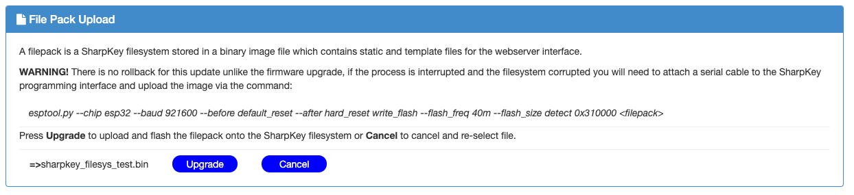
Click on the Upgrade button if you are ready to upload and flash the new filepack into the SharpKey or click Cancel to clear the chosen file. Once you press Upgrade the update procedure will commence, firstly the file will be validated and if valid, file upload will take place and the panel will change showing the status:
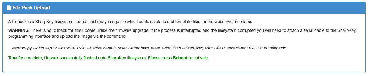
After a successful upload, a green success message will appear advising you to perform a reboot operation.
If a red message appears, reboot the SharpKey and try the filepack upload again. In this situation, where a filepack update has failed, if the SharpKey fails to enter WiFi mode then there is a good chance the filesystem is corrupted. The SharpKey interface will continue
to operate but no access will be possible to the web interface. In order to correct this, an external programming probe needs to be connected to the SharpKey in order to reflash the filesystem. See the technical documentation on a correct procedure. The situation where a filepack upload fails and corruption occurs should be very rare, just ensure power is continuously applied
to the SharpKey during an upload.
Key Map Editor
To cater for unmapped key combinations or keyboards with different layout, configuration and scan codes, the SharpKey allows keyboard map editting. The key maps can be updated via the in-built keymap editor or via a local file save-edit-upload procedure using a tool such as
dhex. If the key mapping file becomes corrupted you can upload a backup from local file or
let the SharpKey reload from the internal default map so another attempt at key map editting can be made.
Given the differences between the various supported machines, the key map editor and it's data differ per model, so a section is dedicated to each machine below, describing the mapping logic and the editor use in making changes. The keymap can only be editted for the active host detected by the SharpKey on startup. If a host is not detected then no keymap editting option will
appear in the left side bar menu.
The basic key map editor, common to all supported hosts, is based on a hex input table, with mapping priority top down, where each entry in the table specifies one key map. Data can be entered in hex or decimal values and some input fields have popover boxes which aid in choosing features such as SHIFT key to aid in the configuration process.
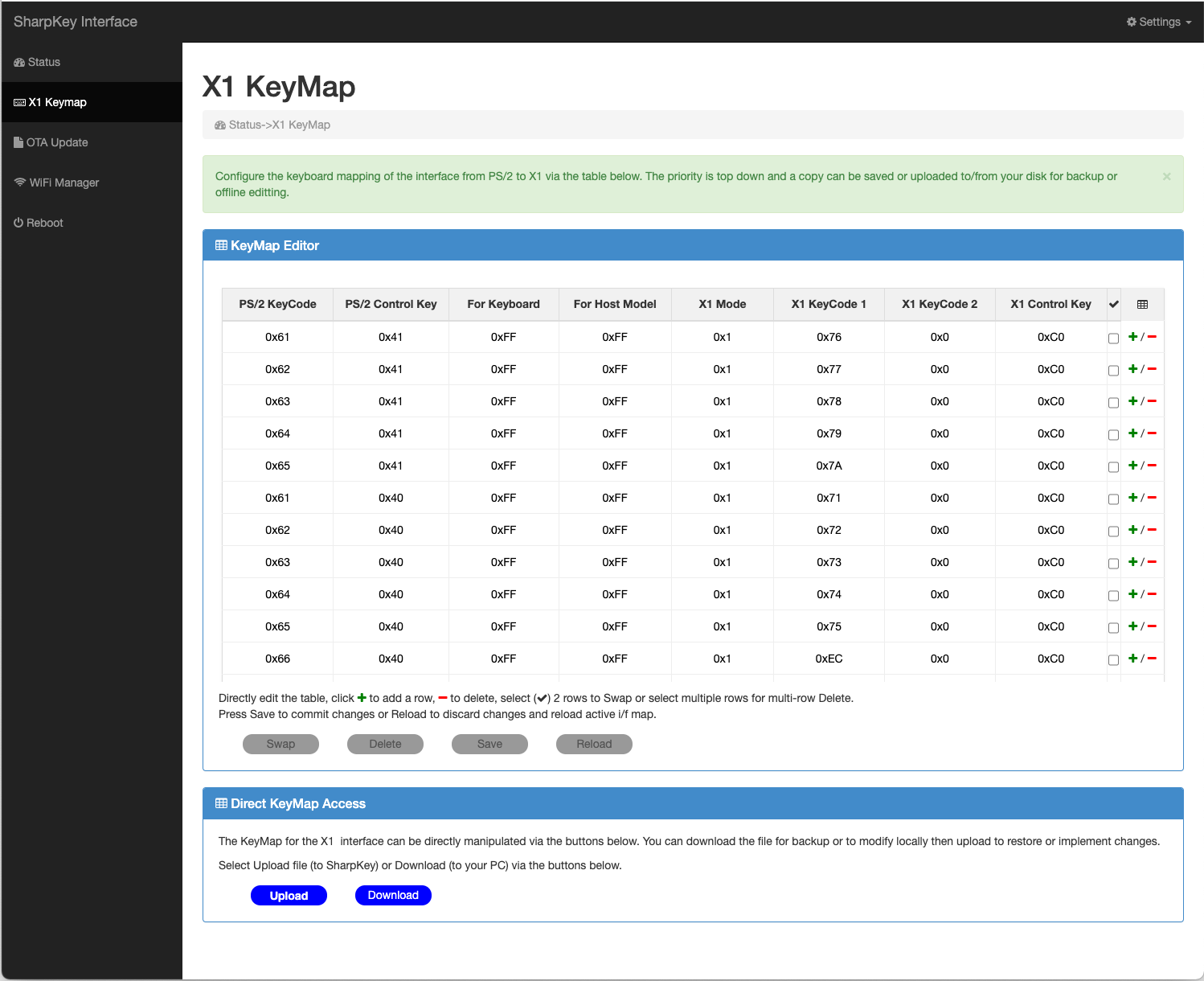
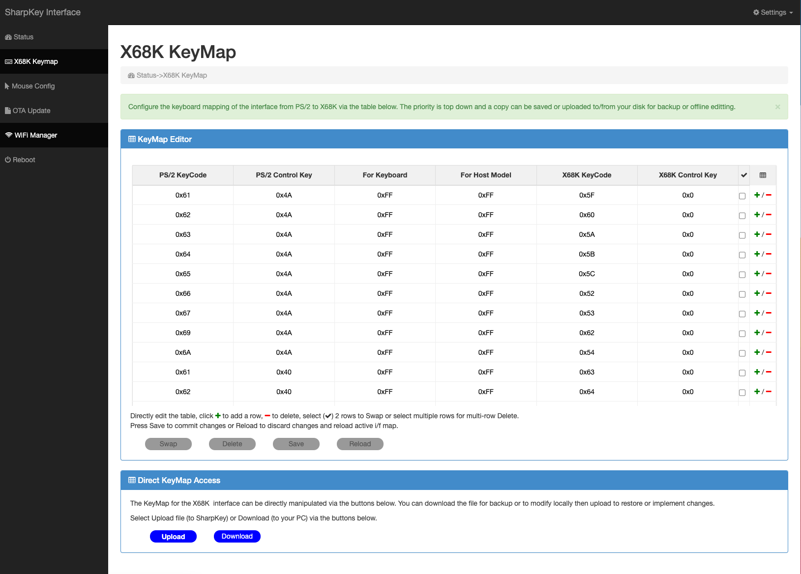
To access the keymap editor of the active host, start the web interface using the Access Point/Client information above and open a browser to load the initial status page, an example of which is below.
Click on the <HOST> KeyMap option in the left sidebar menu. This will start the key map editor screen for the active host which will be similar to the example below.
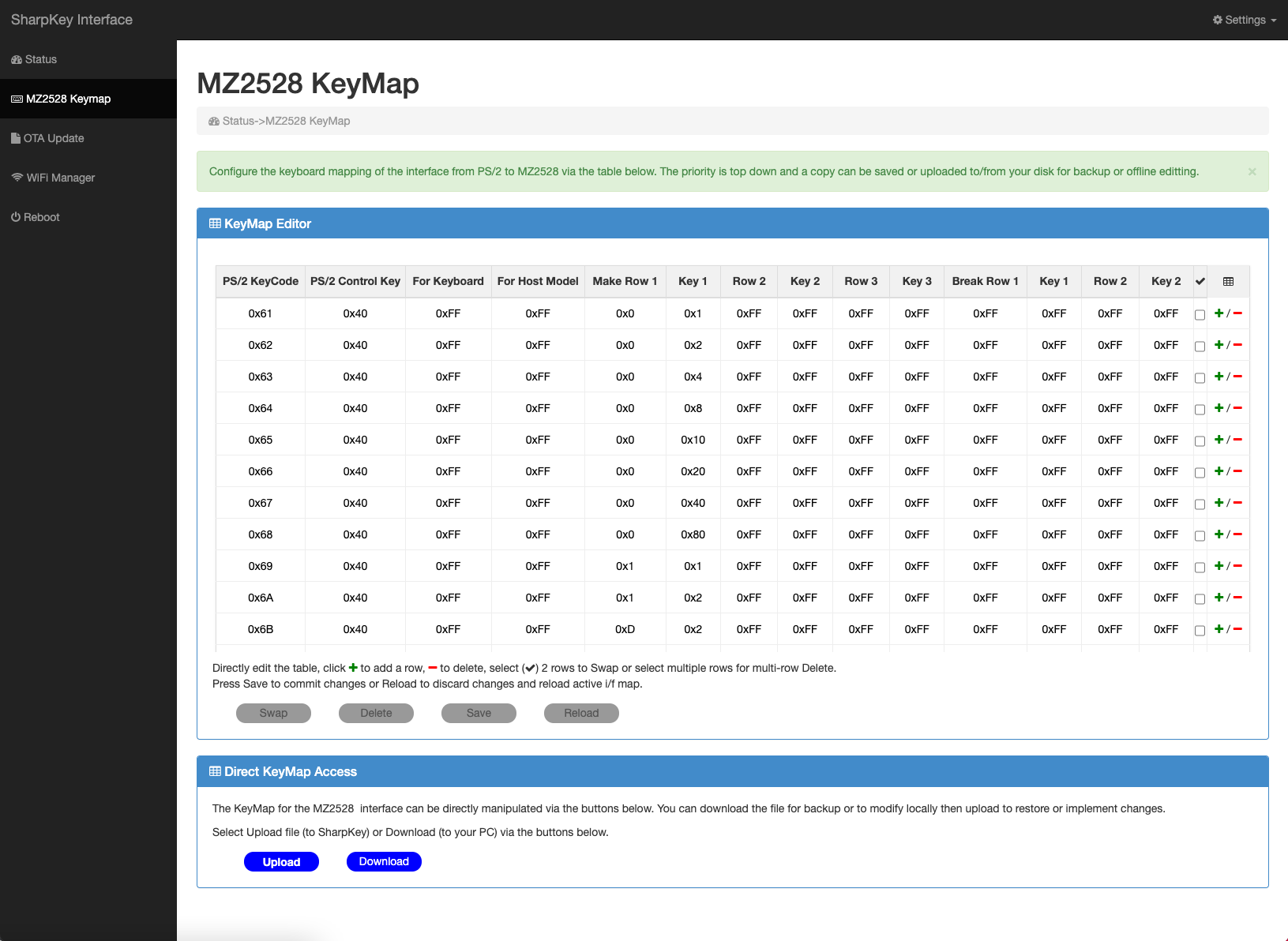
There are 2 panels in the keymap editor, one is for direct input and editting of the key map values, the second is for saving and loading of a keymap file to a local disk. The latter option can be used for backup or to allow external editting of the keymap using local computer tools.
In the
KeyMap Editor panel, a table will be displayed, based on responsive technology which will auto size to the viewable window, use the mouse scroll wheel to scroll down or the TAB/Cursor keys to scroll left and right.
The table headers differ depending on the active host and will be described in more detail in the host sections below.
The editor can add, delete, swap, save changes or reload using the four buttons amd two columns on the right of the table as follows:
- to add a column, click the green + symbol and a blank line will appear on the row below the +. All values will be set to disabled and require completion to become active.
- to delete a single row, click the red - symbol ON the row you wish to delete.
- to delete multiple rows, click on the Tick Box to the right of each row to be deleted. When one or more tick boxes are ticked, the blue Delete button will be made active, press Delete and the rows will be removed.
- to swap TWO rows, click the Tick Box to the right of each row, TWO rows only should be ticked. Once two rows have been ticked, the blue Swap button will be made active, press Swap and the rows will be swapped.
- to save the keymap (make it active on next reboot), once you have made data changes the blue Save button will be made active, click on it to save the changes.
- once changes have been made, the blue Reload button will be made active, clicking this button at any time will discard all changes and reload the keymap.
Messages will be displayed in the status box just above the buttons, this is where errors will be reported if any occur.
Please see the sections below for more specific keymap detail.
Sharp MZ-2500 / MZ-2800 Key Map
The MZ-2500 and MZ-2800 models share a common key map table. In common with other supported host machines, the key map allows targetting a map at a specific keyboard model (ie. Wyse KB-3296) and a specific host variant (ie. MZ-80B on an MZ-2500).
The MZ-2500/MZ-2800 machines use a keyboard which is based on a 13x8 or 14x8 key matrix where all inactive keys see a logic
1 and an active key sees a logic
0. The MZ-2500 keyboard matrix can be visualised in the following tables and image along with the keyboard layout. The first table has the column as the horizontal header and the second table has the row as the horizontal header.
    MZ-2500 Keyboard Map.

     Row     D7        D6        D5        D4        D3        D2        D1        D0
    ----------------------------------------------------------------------------------
      0      F8        F7        F6        F5        F4        F3        F2        F1
      1      KP -      KP +      KP .      KP ,      KP 9      KP 8      F1O       F9
      2      KP 7      KP 6      KP 5      KP 4      KP 3      KP 2      KP 1      KP 0
      3      BREAK     RIGHT     LEFT      DOWN      UP        RETURN    SPACE     TAB
      4       G         F         E        D         C         B         A         / ?
      5       O         N         M        L         K         J         I         H
      6       W         V         U        T         S         R         Q         P
      7       , <       . >       _        YEN |     ^ '¿      Z ¿       Y         X ¿
      8       7 '       6 &       5 %      4 $       3 #       2 "       1 !       0
      9                 [ {       @ `      - =       ; +       : *       9 )       8 (
     10       KP /      KP *      ESC      BACKSPACE INST/DEL  CLR/HOME  COPY      ] }
     11                                    CTRL      KANA      SHIFT     LOCK      GRAPH
     12                                                                  KJ2       KJ1
     13                                                                  HELP      ARGO

     Col      0        1         2         3         4         5         6         7        8        9        10       11       12      13
     --------------------------------------------------------------------------------------------------------------------------------------
     D0       F1       F9        KP 0      TAB       / ?       H         P         X        0        8 (      ] }      GRAPH    KJ1     ARGO
     D1       F2       F10       KP 1      SPACE     A         I         Q         Y        1 !      9 )      COPY     LOCK     KJ2     HELP
     D2       F3       KP 8      KP 2      RETURN    B         J         R         Z        2 "      : *      CLR/HOME SHIFT
     D3       F4       KP 9      KP 3      UP        C         K         S         ^ '¿     3 #      ; +      INST/DEL KANA
     D4       F5       KP ,      KP 4      DOWN      D         L         T         YEN |    4 $      - =      BACKSPACE CTRL
     D5       F6       KP .      KP 5      LEFT      E         M         U         _        5 %      @ `      ESC
     D6       F7       KP +      KP 6      RIGHT     F         N         V         . >      6 &      [ {      KP *
     D7       F8       KP -      KP 7      BREAK     G         O         W         , <      7 '               KP /
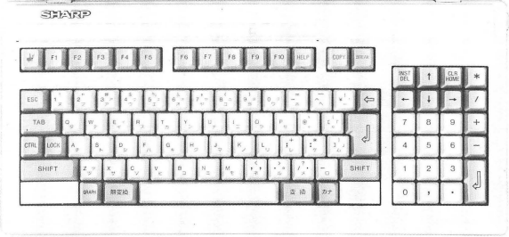
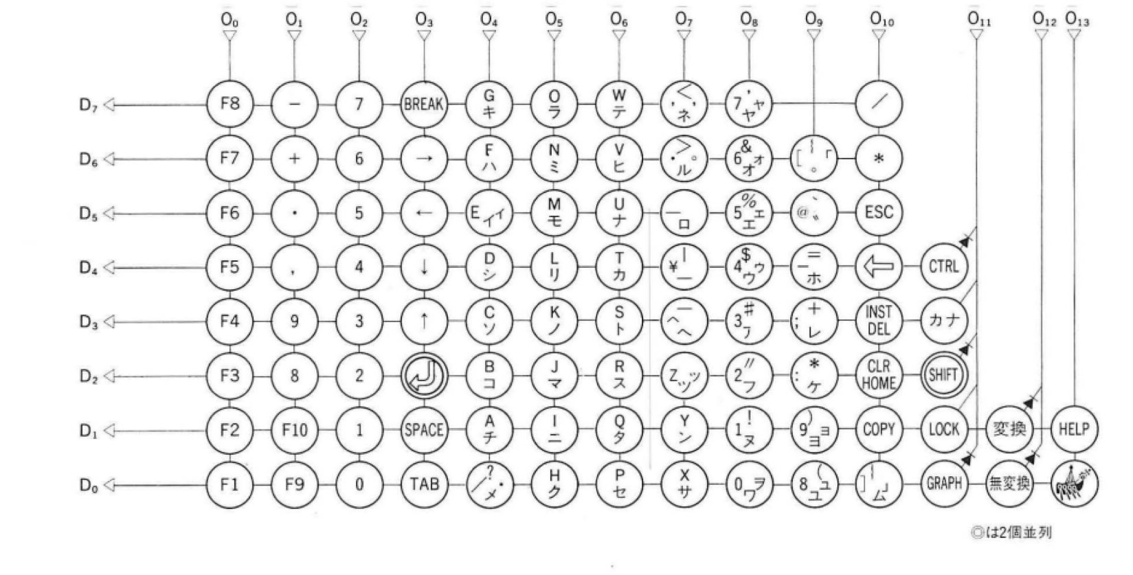
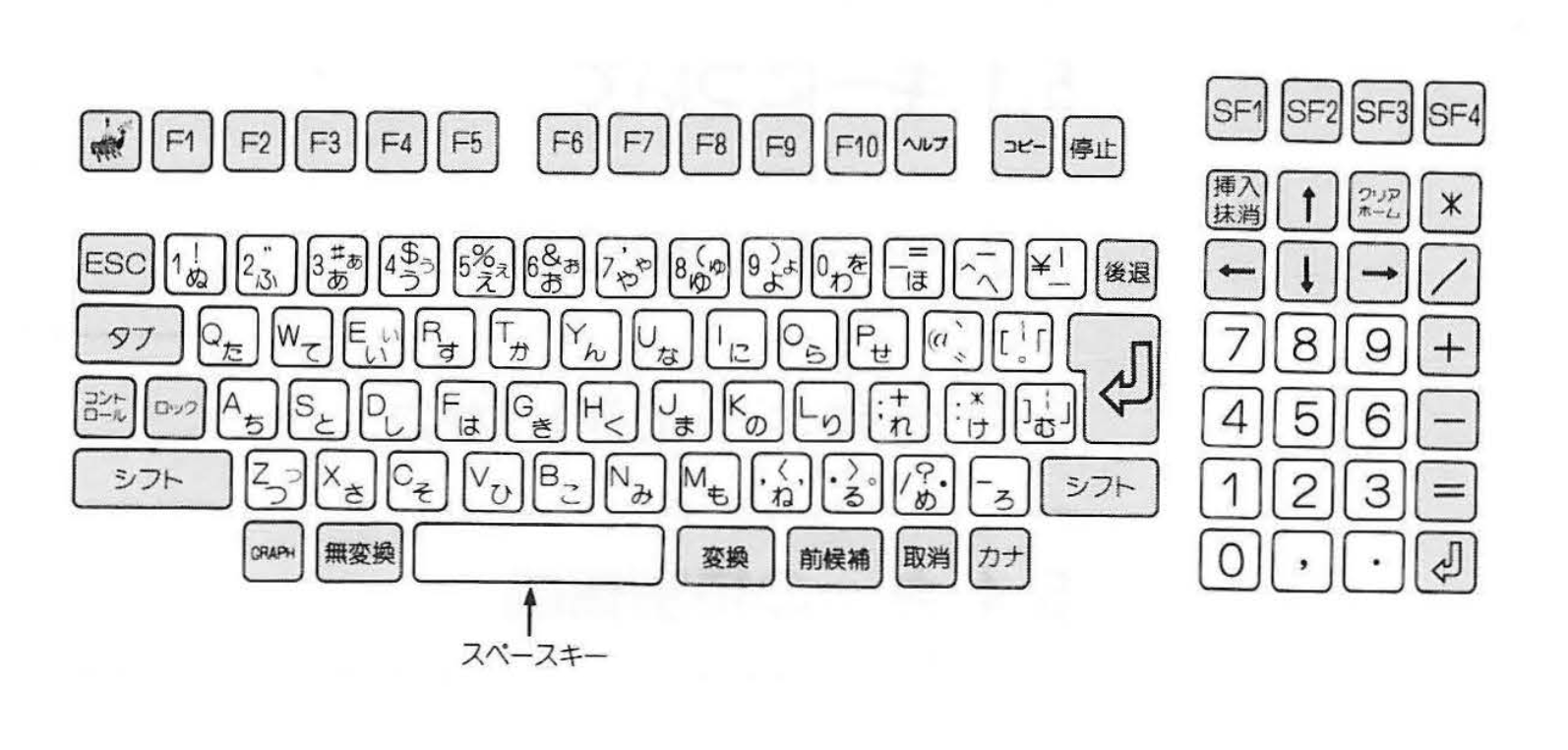
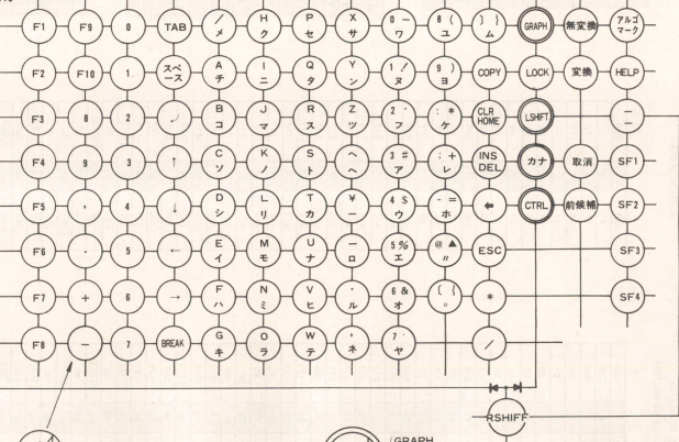
The MZ-2800 keyboard matrix can be visualised in the following images, the first image is the keyboard layout and the second is the keyboard matrix.
A PS/2 key (Bluetooth keyboards are internally mapped to PS/2 keys) may require activation of one or more row/column pairs within the keyboard matrix AND possibly deactivation of another row/column pair. To cater for this, 14 parameters are
provided per single key map, all of which need to be configured or defaulted, which is described below.
The mapping process traverses the mapping table from top to bottom everytime a PS/2 key is pressed and if a key is matched, the MZ-2500/2800 output matrix is updated using a
Make Row parameter which points to a row in the matrix and a
Make Key parameter which sets, via logical OR, the 8 bit column data for that row.
Upto 3 matrix bits can be set (3 key presses on the MZ-2500/2800 keyboard) per PS/2 key. Upto 2 matrix releases can be set per PS/2 key. A key release is used when a modifier may already have been pressed, ie. SHIFT and it needs to be released to set the required key into the matrix. Both set and releases use logic
1 to indicate an active state.
ie. Make Row 1 = 0x01, Make Key 1 = 0x80 - Using the MZ-2500 matrix map below, this combination would see the KeyPad Minus key being pressed on the output matrix which is sent to the MZ-2500 as keyboard input, the MZ-2500 would then react by detecting and acting on a KeyPad Minus key being pressed.
In the mapping table, for the matrix Row and Key values, a set bit = 1 and a reset bit = 0 which is the inverse of the actual MZ-2500/MZ-2800 keyboard matrix state but makes understanding and configuration easier. If the Row is set to 255 (0xFF), which is a marker value indicating an unused parameter, then that particular entry is ignored.
The following table describes each configurable parameter forming a single key map.
| Parameter |
Description |
| PS/2 KeyCode |
This is the raw PS/2 Keyboard Code for any given key excluding E0/E1 or Break modifiers which are reflected in the PS/2 Control Key flag. |
| PS/2 Control Key |
This is the control keys to be matched for any given PS/2 KeyCode. They include SHIFT, CTRL, CAPS, ALT, ALTGR, GUI, FUNC and BREAK (not break key but key break or release). |
| For Keyboard |
This is a flag to specify a particular PS/2 or Bluetooth keyboard model(s) to which this map will be active if the connected keyboard matches. |
| For Host Model |
This is a flag to specify a model or set of models the key map is active for. The MZ-2500 can emulate an MZ-80B, MZ-2000 and MZ-2500 and the MZ-2800 can emulate an MZ-2500 or MZ-2800. |
| Make Row 1 |
This is the row in the MZ-2500/MZ-2800 keyboard matrix to activate when the defined PS/2 KeyCode matches. |
| Make Key 1 |
This is the column in the MZ-2500/MZ-2800 keyboard matrix which will be activated for a matching PS/2 KeyCode. |
| Make Row 2 |
Same as Make Row 1, second row activation if required. 0xFF = disabled. |
| Make Key 2 |
Same as Make Key 1. |
| Make Row 3 |
Same as Make Row 1, third row activation if required. 0xFF = disabled. |
| Make Key 3 |
Same as Make Key 1. |
| Break Row 1 |
This is the row in the MZ-2500/MZ-2800 keyboard matrix to be de-activated, if set, when the defined PS/2 KeyCode matches. |
| Break Key 1 |
This is the column in the MZ-2500/MZ-2800 keyboard matrix which will be de-activated when PS/2 KeyCode matches. |
| Break Row 2 |
Same as Break Row 1, second row to be de-activeted if required. oxFF = disabled. |
| Break Key 2 |
Same as Break Key 1. |
All the keymap parameters are shown in the key map editor using HEX notation, ie:
All the keymap rows are stored in the table and the viewable table size is set according to the browser and/or computer screen size. To view hidden rows, use the mouse scroll wheel.
Data entry can be made in HEX or DECIMAL notation by clicking on a column and entering a value, then click on the next column and enter a value repeating, or click once then use the TAB key for more rapid data entry. Detail for each column
and it's reqired input values can be seen below.
PS/2 KeyCode - This column expects a PS/2 or Bluetooth keyboard scancode which can be found in your keyboard user manual or on the web where there are many references.
ie. the key
A has a generic scancode value of 0x1C. HEX codes are not that user friendly and as there are many keyboards with many differing scancodes it is not possible to offer a picklist.
PS/2 scancodes can be represented by multiple bytes, only use the primary byte and ignore extended code seqeuences such as E0/E1/F0 as these are internally processed and the corresponding feature selected in the
PS/2 Control Key column.
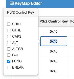
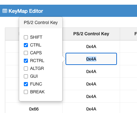
PS/2 Control Key - This parameter indicates which modifier keys (ie. CTRL, SHIFT etc) are pressed along with the PS/2 scancode in order to make a match. As a hex value is required, the modifier values are as follows:
| Modifier Key | Value | Modifier Key | Value | Modifier Key | Value | Modifier Key | Value |
| SHIFT | 0x01 | CTRL | 0x02 | CAPS | 0x04 | ALT | 0x08 |
| ALTGR | 0x10 | GUI | 0x20 | FUNC | 0x40 | BREAK | 0x80 |
A popover picklist has been added to this field, when you click in the field (tabbing into the field wont show the popover) a popover will appear, example below. Click on the key modifiers you require to be matched along with the PS/2 scancode in order for the map to make a match and process the rest of the mapping parameters.
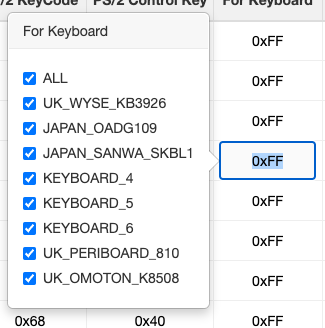
For Keyboard - This column expects an 8bit value, each bit indicates a supported keyboard model and if the active keyboard matches one of the set bits the rest of the mapping parameters will be processed.
Valid values are in the table below with five keyboard models defined and the rest are place markers ready for assigning to a custom keyboard. ie. your own keyboard mappings could be assigned to
Keyboard 4 and using the hotkey SHIFT+CTRL+ESC+KeyPad_4 will set the active keyboard to
Keyboard 4 and your mappings will then be active.
A value of 255 (0xFF) in this field enables the keymap for all keyboard models. Most of the default mappings are enabled for all keyboards, placing your own mapping higher up in the mapping table makes it take priority over the standard map.
| Keyboard Model | Value | Keyboard Model | Value | Keyboard Model | Value | Keyboard Model | Value |
| UK WYSE KB3926 | 0x01 | JAPAN OADG109 | 0x02 | JAPAN Sanwa SKB-L1 | 0x04 | Keyboard 4 | 0x08 |
| Keyboard 5 | 0x10 | Keyboard 6 | 0x20 | UK Periboard 810 (BT) | 0x40 | UK OMOTON K8508 (BT) | 0x80 |
A popover picklist has been added to this field, when you click in the field (tabbing into the field wont show the popover) a popover will appear, example below. Click on the keyboard models and your mapping will be enabled for the indicated keyboard models or use ALL for all keyboards.
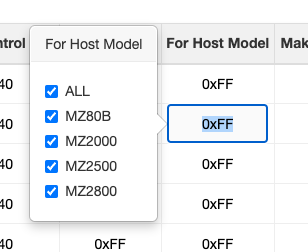
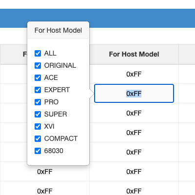
For Host Model - This column expects an 8bit value, each bit indicating a machine model the map will be active with. The MZ-2500 is capable of running as an MZ-80B, MZ-2000 and MZ-2550 with each having slightly different key mappings and the MZ-2800 also has differences so this field is used to target a key
map at a particular machine or set of machines.
Valid values are in the table below with a value of 255 (0xFF) indicating all host models.
| Host Model | Value | Host Model | Value | Host Model | Value | KHost Model | Value |
| MZ80B | 0x01 | MZ2000 | 0x02 | MZ2500 | 0x04 | MZ2800 | 0x08 |
A popover picklist has been added to this field, when you click in the field (tabbing into the field wont show the popover) a popover will appear, example below. Click on the Host Model and your mapping will be enabled for the indicated models or use ALL for all possible hosts.
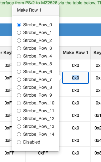
Make Row 1, Row 2, Row 3, Break Row 1, Row 2 - This column expects an 4bit value representing a strobe row from 0 to 15. A value of 255 (0xFF) indicates the parameter is not used. Select the row to target in the output matrix when you need to activate/deactivate a key that the host will see.
A popover select list has been added to this field, when you click in the field (tabbing into the field wont show the popover) a popover will appear, example below. Click on Strobe Row you wish to select, the strobe rows and columns appear in the keyboard matrix outlined in the MZ-2500/MZ-2800 documentation or use the MZ-2500 keyboard table above.
Default Mapping Table
The table below describes the default map in a easy to understand format.
| MZ-2500 Key |
MZ-2800 Key |
PS/2 Key |
Description |
PS/2 Keyboard |
| LOCK |
LOCK* |
Caps Lock |
Shifts and locks upper/lower case characters. Press once to lock upper case, LED light comes on, press again to release and return to lower case characters. |
Wyse KB-3926 |
| HELP |
HELP* |
F11 |
HELP functionality |
|
| BREAK |
BREAK* |
Pause |
BREAK key. PS/2 normally use CTRL+BREAK to generate a BREAK but the MZ-2500 requires SHIFT+BREAK which doesnt yield BREAK, thus a mapping is created for SHIFT+PAUSE (which is also the same key as BREAK) to create an MZ-2500 BREAK. |
|
| COPY |
COPY* |
F12 |
COPY functionality |
|
| CLR |
CLR* |
Shift+Home |
Clear screen |
|
| HOME |
HOME* |
Home |
Set cursor to 0,0 position ie. HOME. |
|
| INST |
INST* |
Insert |
Insert characters at cursor position. |
|
| DEL |
DEL* |
Delete |
Delete characters from cursor position. |
|
| ARGO |
ARGO |
Print Screen |
ARGO functionality. ie. Bring up applets menu in BASIC v2 |
|
| GRAPH |
GRAPH |
Left GUI |
Change to Graphics character entry. |
|
| Yen |
Yen |
|\ |
Insert a Yen symbol |
|
| KANA |
KANA |
Right GUI |
Select KANA functionality. |
|
| KJ1 Sentence |
KJ1 Sentence |
Left ALT |
KJ1 functionality |
|
| KJ2 Transform |
KJ2 Transform |
Right ALT |
KJ2 functionality |
|
| |
PREVIOUS* |
PGDN |
Previous Key |
|
| |
CANCEL* |
Right CTRL |
Cancel Key |
|
| |
SF1 |
|
Special Function 1 |
Not yet mapped |
| |
SF2 |
|
Special Function 2 |
Not yet mapped |
| |
SF3 |
|
Special Function 3 |
Not yet mapped |
| |
SF4 |
|
Special Function 4 |
Not yet mapped |
* = Written in Japanese on the MZ-2800.
All other keys are as per the symbol on the PS/2 keyboard. The Num Lock key toggles the keypad between numeric and cursor functions. The keyboard mapping passes through modifier keys unless there is an exact map, ie. SHIFT. Thus key combinations not catered for
in the mapping table may work, ie. SHIFT+KANA, albeit you can always edit the map via the web interface above.
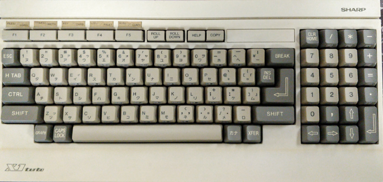
Sharp X1 Key Map
The Sharp X1 series includes the X1, X1 Turbo and X1 Turbo Z. The mapping is more conventional in so much that a PS/2 scancode (Bluetooth scancodes are mapped internally to PS/2 scancodes) maps to an X1 scancode rather than a key matrix like the Sharp MZ series machines. The PS/2 protocol sends multiple bytes depending on which key is pressed and the internal
mapping massages this into an 8bit KeyCode and 8bit modifier Control keys. The X1 is similar, requiring an 8bit key code plus an 8bit modifier code for the original model. The Turbo/Turbo Z series has a mode switch, Mode A (original) and Mode B, where Mode B sends a more rapid 24bit response and is used for gaming. The 24bits in Mode B represent a bit map,
each bit mapped to a single key, so a different mapping technique is needed if the SharpKey is mapping keys for Mode B.
The Sharp X1 Turbo layout can be seen in the image below. The keys return an ASCII value + modifier byte on each key press and release.
Mode A is used for all Sharp X1 models and is used for general keyboard usage. It sends key data as an ascii code + control modifier keys in the format <Control Bits><Ascii Key Code>. The bit values for the Control byte can be seen in the table below and they use negative logic, ie.
0 is active,
1 is inactive. When a PS/2 key is pressed, the control bits are updated if it is a control key, if the key is
a normal key then the control + keycode is sent to the host.
| 7 |
6 |
5 |
4 |
3 |
2 |
1 |
0 |
| TENKEY |
KIN |
REP |
GRPH |
CAPS |
KANA |
SFT |
CTRL |
Mode B is intended for gaming and sends a subset of keys as a direct 24bit representation on each press/release change. The transmission protocol is also sped up to minimise time lag. The data is sent in the format <BYTE1><BYTE2><BYTE3>. The bit values can be seen in the table below and they use negative logic, ie.
0 is active,
1 is inactive. When a PS/2 or Bluetooth key is pressed,
the required bit in this bitmap should be set (
0) to create the key mapping.
| |
7 |
6 |
5 |
4 |
3 |
2 |
1 |
0 |
| BYTE1 |
Q |
W |
E |
A |
D |
Z |
X |
C |
| BYTE2 |
7 |
4 |
1 |
8 |
2 |
9 |
6 |
3 |
| BYTE3 |
ESC |
1 |
- |
+ |
* |
HTAB |
SP |
RET |
The mapping process traverses the mapping table from top to bottom everytime a PS/2 or Bluetooth key is pressed and if a key is matched then the resulting output parameters are serialised and sent to the Sharp X1. As the Sharp X1 Turbo/Turbo Z have a Mode B game mode, the mapping table parameters cater for a direct key + modifier map or a key to 24bit (3 bytes) map.
The following table describes each configurable parameter forming a single key map.
| Parameter |
Description |
| PS/2 KeyCode |
This is the raw PS/2 Keyboard Code for any given key excluding E0/E1 or Break modifiers which are reflected in the PS/2 Control Key flag. |
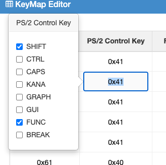
| PS/2 Control Key |
This is the control keys to be matched for any given PS/2 KeyCode. They include SHIFT, CTRL, CAPS, KANA, GRAPH, GUI, FUNC and BREAK (not break key but key break or release). |
| For Keyboard |
This is a flag to specify a particular PS/2 or Bluetooth keyboard model(s) to which this map will be active if the connected keyboard matches. |
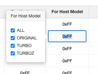
| For Host Model |
This is a flag to specify a model or set of models the key map is active for. The X1 came in 3 main releases, the Original series, Turbo and TurboZ series. |
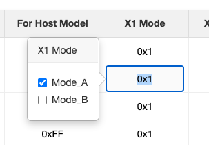
| X1 Mode |
This is a flag which specifies the keyboard mode, for an X1 it has 2 modes, a Mode A which is standard operation and Mode B which is gaming mode. |
| X1 KeyCode1 |
This parameter, in Mode A, specifies the actual Key Code the Sharp X1 expects for normal keyboard input. In Mode B this parameter specifies Byte 1 of the 24bit word, each bit within specifies a specific key being pressed. |
| X1 KeyCode2 |
This parameter, in Mode B, specifies Byte 2 of the 24bit word, each bit within specifies a specific key being pressed. |
| X1 Control Key |
This parameter, in Mode A, specifies the keyboard modifiers, ie. SHIFT, which are being activated along with the keycode. In Mode B this parameter specifies Byte 3 of the 24bit word, each bit within specifies a specific key being pressed. |
All the keymap parameters are shown in the key map editor using HEX notation, ie:
All the keymap rows are stored in the table and the viewable table size is set according to the browser and/or computer screen size. To view hidden rows, use the mouse scroll wheel.
Data entry can be made in HEX or DECIMAL notation by clicking on a column and entering a value, then click on the next column and enter a value repeating, or click once then use the TAB key for more rapid data entry. Detail for each column
and it's reqired input values can be seen below.
PS/2 KeyCode - This column expects a PS/2 or Bluetooth keyboard scancode which can be found in your keyboard user manual or on the web where there are many references.
ie. the key
A has a generic scancode value of 0x1C. HEX codes are not that user friendly and as there are many keyboards with many differing scancodes it is not possible to offer a picklist.
PS/2 scancodes can be represented by multiple bytes, only use the primary byte and ignore extended code seqeuences such as E0/E1/F0 as these are internally processed and the corresponding feature selected in the
PS/2 Control Key column.
PS/2 Control Key - This parameter indicates which modifier keys (ie. CTRL, SHIFT etc) are pressed along with the PS/2 scancode in order to make a match. As a hex value is required, the modifier values are as follows:
| Modifier Key | Value | Modifier Key | Value | Modifier Key | Value | Modifier Key | Value |
| SHIFT | 0x01 | CTRL | 0x02 | CAPS | 0x04 | KANA | 0x08 |
| GRAPH | 0x10 | GUI | 0x20 | FUNC | 0x40 | BREAK | 0x80 |
A popover picklist has been added to this field, when you click in the field (tabbing into the field wont show the popover) a popover will appear, example below. Click on the key modifiers you require to be matched along with the PS/2 scancode in order for the map to make a match and process the rest of the mapping parameters.
For Keyboard - This column expects an 8bit value, each bit indicates a supported keyboard model and if the active keyboard matches one of the set bits the rest of the mapping parameters will be processed.
Valid values are in the table below with five keyboard models defined and the rest are place markers ready for assigning to a custom keyboard. ie. your own keyboard mappings could be assigned to
Keyboard 4 and using the hotkey SHIFT+CTRL+ESC+KeyPad_4 will set the active keyboard to
Keyboard 4 and your mappings will then be active.
A value of 255 (0xFF) in this field enables the keymap for all keyboard models. Most of the default mappings are enabled for all keyboards, placing your own mapping higher up in the mapping table makes it take priority over the standard map.
| Keyboard Model | Value | Keyboard Model | Value | Keyboard Model | Value | Keyboard Model | Value |
| UK WYSE KB3926 | 0x01 | JAPAN OADG109 | 0x02 | JAPAN Sanwa SKB-L1 | 0x04 | Keyboard 4 | 0x08 |
| Keyboard 5 | 0x10 | Keyboard 6 | 0x20 | UK Periboard 810 (BT) | 0x40 | UK OMOTON K8508 (BT) | 0x80 |
A popover picklist has been added to this field, when you click in the field (tabbing into the field wont show the popover) a popover will appear, example below. Click on the keyboard models and your mapping will be enabled for the indicated keyboard models or use ALL for all keyboards.
For Host Model - This column expects an 8bit value, each bit indicating a machine model the map will be active with. The Sharp X1 was released in many variants and each model may have differences which require specific key maps.
Valid values are in the table below with a value of 255 (0xFF) indicating all host models.
| Host Model | Value | Host Model | Value | Host Model | Value | Host Model | Value |
| Sharp X1 Original | 0x01 | Sharp X1 Turbo | 0x02 | Sharp X1 TurboZ | 0x04 | | |
A popover picklist has been added to this field, when you click in the field (tabbing into the field wont show the popover) a popover will appear, example below. Click on the Host Model and your mapping will be enabled for the indicated models or use ALL for all possible hosts.
X1 Mode - This parameter indicates for which mode of operation the key map is active. If Mode A, then parameters
X1 KeyCode 1 and
X1 Control Key are active, if Mode B, parameters
X1 KeyCode 1 (BYTE1),
X1 KeyCode 2 (BYTE2) and
X1 Control Key (BYTE 3) are active.
As a hex value is required, the modifier values are as follows:
| Mode | Value | Mode | Value |
| Mode A | 0x01 | Mode B | 0x02 |
A popover picklist has been added to this field, when you click in the field (tabbing into the field wont show the popover) a popover will appear, example below. Click on the Mode and your mapping will be enabled for the indicated mode.
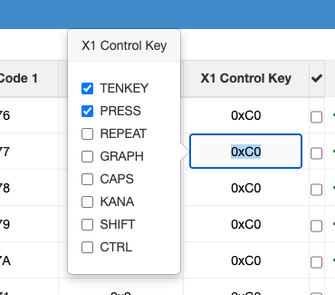
X1 Control Key - This parameter indicates which modifier keys (ie. CTRL, SHIFT etc) are pressed along with the X1 KeyCode and sent to the Sharp X1. As a hex value is required, the modifier values are as follows:
| Modifier Key | Value | Modifier Key | Value | Modifier Key | Value | Modifier Key | Value |
| SHIFT | 0x01 | CTRL | 0x02 | CAPS | 0x04 | KANA | 0x08 |
| GRAPH | 0x10 | GUI | 0x20 | FUNC | 0x40 | BREAK | 0x80 |
A popover picklist has been added to this field, when you click in the field (tabbing into the field wont show the popover) a popover will appear, example below. Click on the Control keys required and these flags will be sent to the X1 along with the X1 KeyCode for the given PS/2 + PS/2 Control key combination.
Default Mapping Table
The table below describes the default map in a easy to understand format.
| X1 Key |
PS/2 Key |
Description |
| XFER |
F10 |
Actuate XFER key |
| HELP |
F11 |
Actuate HELP key |
| COPY |
F12 |
Actuate COPY key |
| Roll Up |
PGUP |
Actuate Roll Up key |
| Roll Down |
PGDN |
Actuate Roll Down key |
| CLR |
SHIFT + HOME |
Actuate CLR key |
| ARGO |
PRTSCR |
Actuate ARGO key |
| BREAK |
PAUSE |
Actuate BREAK key |
| GRAPH |
LeftGUI |
Actuate GRAPH key |
| KJ1 Sentence |
LeftALT |
Actuate KJ1 key |
| KJ2 Transform |
RightALT |
Actuate KJ2 key |
| KANA |
RightGUI |
Actuate KANA key |
All other keys are as per the symbol on the PS/2 keyboard. The Num Lock key toggles the keypad between numeric and cursor functions. The keyboard mapping passes through modifier keys unless there is an exact map, ie. SHIFT. Thus key combinations not catered for
in the mapping table may work, ie. SHIFT+KANA, albeit you can always edit the map via the web interface above.
Sharp X68000 Key Map
The Sharp X68000 series includes the Original, ACE, Expert, Super, Pro, XVI, Compact and 68030 models. There also exists some specialised 'Red' models. The mapping is conventional and similar in concept
to the PS/2 protocol, ie. a scancode is sent over an asynchronous serial wire for every key pressed. This makes the mapping easier as it is a relative 1:1 map.
Below are the X68000 keyboard layout image and scan code image per key. These can be used in preparing map parameters.
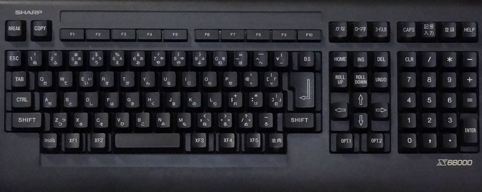
X68000 Scan Codes
,---. ,---.    ,-------------------,    ,-------------------.  ,-----------. ,---------------.
| 61| | 62|    | 63| 64| 65| 66| 67|    | 68| 69| 6A| 6B| 6C|  | 5A| 5B| 5C| | 5D| 52| 53| 54|
`---' `---'    `-------------------'    `-------------------'  `-----------' `---------------'
,-----------------------------------------------------------.  ,-----------. ,---------------.
| 01| 02| 03| 04| 05| 06| 07| 08| 09| 0A| 0B| 0C| 0D| 0E| 0F|  | 36| 5E| 37| | 3F| 40| 41| 42|
|-----------------------------------------------------------|  |------------ |---------------|
|  10 | 11| 12| 13| 14| 15| 16| 17| 18| 19| 1A| 1B| 1C|     |  | 38| 39| 3A| | 43| 44| 45| 46|
|------------------------------------------------------. 1D |  `---=====---' |---------------|
|  71  | 1E| 1F| 20| 21| 2l| 23| 24| 25| 26| 27| 28| 29|    |   ___| 3C|___  | 47| 48| 49| 4A|
|-----------------------------------------------------------|  | 3B|---| 3D| |-----------|---|
|  70    | 2A| 2B| 2C| 2D| 2E| 2F| 30| 31| 32| 33| 34|   70 |  `---| 3E|---' | 4B| 4C| 4D|   |
`-----------------------------------------------------------|  .---=====---. |-----------| 4E|
       | 5F| 55 | 56 |     35     | 57 | 58 | 59 | 60|         |  72 |  73 | | 4F| 50| 51|   |
       `---------------------------------------------'         `-----------' `---------------'
The mapping process traverses the mapping table from top to bottom everytime a PS/2 key is pressed (Bluetooth scancodes are mapped internally to PS/2 scancodes) and if a key is matched then the resulting output parameters are serialised and sent to the Sharp X68000.
The following table describes each configurable parameter forming a single key map.
| Parameter |
Description |
| PS/2 KeyCode |
This is the raw PS/2 Keyboard Code for any given key excluding E0/E1 or Break modifiers which are reflected in the PS/2 Control Key flag. |
| PS/2 Control Key |
This is the control keys to be matched for any given PS/2 KeyCode. They include SHIFT, CTRL, CAPS, ALT, ALTGR, GUI, FUNC and BREAK (not break key but key break or release). |
| For Keyboard |
This is a flag to specify a particular PS/2 or Bluetooth keyboard model(s) to which this map will be active if the connected keyboard matches. |
| For Host Model |
This is a flag to specify a model or set of models the key map is active for. The MZ-2500 can emulate an MZ-80B, MZ-2000 and MZ-2500 and the MZ-2800 can emulate an MZ-2500 or MZ-2800. |
| X68K KeyCode |
This parameter represents the key value to be sent to the X68000 when the PS/2 KeyCode + PS/2 Control Key are matched. |
| X68K Control Key |
This parameter represents the control keys which are sent to the X68000 when the PS/2 KeyCode + PS/2 Control Key are matched. |
All the keymap parameters are shown in the key map editor using HEX notation, ie:
All the keymap rows are stored in the table and the viewable table size is set according to the browser and/or computer screen size. To view hidden rows, use the mouse scroll wheel.
Data entry can be made in HEX or DECIMAL notation by clicking on a column and entering a value, then click on the next column and enter a value repeating, or click once then use the TAB key for more rapid data entry. Detail for each column
and it's reqired input values can be seen below.
PS/2 KeyCode - This column expects a PS/2 or Bluetooth keyboard scancode which can be found in your keyboard user manual or on the web where there are many references.
ie. the key 'A' has a generic scancode value of 0x1C. HEX codes are not that user friendly and as there are many keyboards with many differing scancodes it is not possible to offer a picklist.
PS/2 scancodes can be represented by multiple bytes, only use the primary byte and ignore extended code seqeuences such as E0/E1/F0 as these are internally processed and the corresponding feature selected in the
PS/2 Control Key column.
PS/2 Control Key - This parameter indicates which modifier keys (ie. CTRL, SHIFT etc) are pressed along with the PS/2 scancode in order to make a match. As a hex value is required, the modifier values are as follows:
| Modifier Key | Value | Modifier Key | Value | Modifier Key | Value | Modifier Key | Value |
| SHIFT | 0x01 | CTRL | 0x02 | CAPS | 0x04 | KANA | 0x08 |
| GRAPH | 0x10 | GUI | 0x20 | FUNC | 0x40 | BREAK | 0x80 |
A popover picklist has been added to this field, when you click in the field (tabbing into the field wont show the popover) a popover will appear, example below. Click on the key modifiers you require to be matched along with the PS/2 scancode in order for the map to make a match and process the rest of the mapping parameters.
For Keyboard - This column expects an 8bit value, each bit indicates a supported keyboard model and if the active keyboard matches one of the set bits the rest of the mapping parameters will be processed.
Valid values are in the table below with five keyboard models defined and the rest are place markers ready for assigning to a custom keyboard. ie. your own keyboard mappings could be assigned to
Keyboard 4 and using the hotkey SHIFT+CTRL+ESC+KeyPad_4 will set the active keyboard to
Keyboard 4 and your mappings will then be active.
A value of 255 (0xFF) in this field enables the keymap for all keyboard models. Most of the default mappings are enabled for all keyboards, placing your own mapping higher up in the mapping table makes it take priority over the standard map.
| Keyboard Model | Value | Keyboard Model | Value | Keyboard Model | Value | Keyboard Model | Value |
| UK WYSE KB3926 | 0x01 | JAPAN OADG109 | 0x02 | JAPAN Sanwa SKB-L1 | 0x04 | Keyboard 4 | 0x08 |
| Keyboard 5 | 0x10 | Keyboard 6 | 0x20 | UK Periboard 810 (BT) | 0x40 | UK OMOTON K8508 (BT) | 0x80 |
A popover picklist has been added to this field, when you click in the field (tabbing into the field wont show the popover) a popover will appear, example below. Click on the keyboard models and your mapping will be enabled for the indicated keyboard models or use ALL for all keyboards.
For Host Model - This column expects an 8bit value, each bit indicating a machine model the map will be active with. The Sharp X68000 was released in many variants and each model may have differences which require a specific key map.
Valid values are in the table below with a value of 255 (0xFF) indicating all host models.
| Host Model | Value | Host Model | Value | Host Model | Value | Host Model | Value |
| X68000 Original | 0x01 | ACE | 0x02 | Expert | 0x04 | Super | 0x08 |
| Pro | 0x10 | XVI | 0x20 | Compact | 0x40 | 68030 | 0x80 |
A popover picklist has been added to this field, when you click in the field (tabbing into the field wont show the popover) a popover will appear, example below. Click on the Host Model and your mapping will be enabled for the indicated models or use ALL for all possible hosts.
X68K KeyCode - This column expects the X68000 key code to be sent to the X68000 when the selected PS/2 or Bluetooth KeyCode + PS/2 Control code is pressed.
ie. for the PS/2 scancode representing the key
A, 0x1E is sent to the X68000.
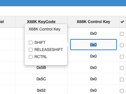
X68K Control Key - This parameter indicates which modifier keys (ie. CTRL, SHIFT etc) are sent along with the X68K KeyCode to the X68000. As a hex value is required, the modifier values are as follows:
| Modifier Key | Value | Modifier Key | Value | Modifier Key | Value | Modifier Key | Value |
| SHIFT | 0x80 | RELEASESHIFT | 0x40 | SHIFT | 0x01 | | |
A popover picklist has been added to this field, when you click in the field (tabbing into the field wont show the popover) a popover will appear, example below. Click on the key modifiers you require to be sent with the X68K KeyCode to the X68000 when a match is made.
Default Mapping Table
The table below describes the default map in a easy to understand format.
| X68000 Key |
PS/2 Key |
Description |
| Hiragana |
RightCtrl + F1 |
Actuates Hiragana key |
| Full Width |
RightCtrl + F2 |
Actuates FullWidth key |
| Katakana |
RightCtrl + F3 |
Actuates Katakana key |
| Romaji |
RightCtrl + F4 |
Actuates Romaji key |
| Tranpose |
RightCtrl + F5 |
Actuates Transpose key |
| Symbol |
RightCtrl + F6 |
Actuates Symbol key |
| CodeInput |
RightCtrl + F7 |
Actuates CodeInput key |
| Copy |
RightCtrl + F9 |
Actuates Copy key |
| Help |
RightCtrl + F10 |
Actuates Help key |
| OPT.1 |
F11 |
Actuates OPT.1 key |
| OPT.2 |
F12 |
Actuates OPT.2 key |
| BREAK |
SHIFT + PAUSE |
Actuates BREAK key |
| XF1 |
LeftGUI |
Actuates XF1 key |
| XF2 |
LeftALT |
Actuates XF2 key |
| XF3 |
RightALT |
Actuates XF3 key |
| XF4 |
RightGUI |
Actuates XF4 key |
| XF5 |
MENU |
Actuates XF5 key |
| UNDO |
END |
Actuates UNDO key |
| Roll Up |
PGUP |
Actuates Roll Up key |
| Roll Down |
PGDN |
Actuates Roll Down key |
| CLR |
SHIFT + HOME |
Actuates CLR key |
All other keys are as per the symbol on the PS/2 keyboard. The Num Lock key toggles the keypad between numeric and cursor functions. The keyboard mapping passes through modifier keys unless there is an exact map, ie. SHIFT. Thus key combinations not catered for
in the mapping table may work, ie. SHIFT+KANA, albeit you can always edit the map via the web interface above.
Hot Keys
Hot keys are special key combinations to enable/disable a keyboard feature. When a feature is selected via a Hot Key it is commited to permanent storage and remains active through power cycles.
The following hotkeys are currently defined:
| Active Host |
Hot Key |
Persisted |
Feature |
| All |
SHIFT+CTRL+ESC+ 1 |
Yes |
Select Keyboard Model UK KB-3926 |
| All |
SHIFT+CTRL+ESC+ 2 |
Yes |
Select Keyboard Model JAPAN OADG109 |
| All |
SHIFT+CTRL+ESC+ 3 |
Yes |
Select Keyboard Model JAPAN Sanwa SKB-L1 |
| All |
SHIFT+CTRL+ESC+ 4 |
Yes |
Select Keyboard Model Keyboard_4 |
| All |
SHIFT+CTRL+ESC+ 5 |
Yes |
Select Keyboard Model Keyboard_5 |
| All |
SHIFT+CTRL+ESC+ 6 |
Yes |
Select Keyboard Model Keyboard_6 |
| All |
SHIFT+CTRL+ESC+ 7 |
Yes |
Select Keyboard Model UK Periboard 810 (Bluetooth) |
| All |
SHIFT+CTRL+ESC+ 8 |
Yes |
Select Keyboard Model UK OMOTON K8508 (Bluetooth) |
| All |
SHIFT+CTRL+ESC+ 0 |
Yes |
Select STANDARD Map Keyboard |
| MZ-2500 |
SHIFT+CTRL+ESC+KeyPad 1 |
Yes |
Select keymap for an MZ-2500 |
| MZ-2800 |
SHIFT+CTRL+ESC+KeyPad 1 |
Yes |
Select keymap for an MZ-2800 |
| MZ-2500 |
SHIFT+CTRL+ESC+KeyPad 2 |
Yes |
Select keymap for an MZ-2000 |
| MZ-2500 |
SHIFT+CTRL+ESC+KeyPad 3 |
Yes |
Select keymap for an MZ-80B |
| X1 |
SHIFT+CTRL+ESC+KeyPad 1 |
Yes |
Select keymap for an Original X1 |
| X1 |
SHIFT+CTRL+ESC+KeyPad 2 |
Yes |
Select keymap for a Turbo X1 |
| X1 |
SHIFT+CTRL+ESC+KeyPad 3 |
Yes |
Select keymap for a TurboZ X1 |
| X1 |
SHIFT+CTRL+ESC+KeyPad 0 |
Yes |
Select keymap for a all models, ie. any X1 model key map will become active. |
| X1 |
SHIFT+CTRL+ESC+KeyPad 7 |
No |
Switch to keyboard Mode A |
| X1 |
SHIFT+CTRL+ESC+KeyPad 9 |
No |
Switch to keyboard Mode B |
| X68000 |
SHIFT+CTRL+ESC+KeyPad 1 |
Yes |
Select Original Model X68000 key map |
| X68000 |
SHIFT+CTRL+ESC+KeyPad 2 |
Yes |
Select ACE Model X68000 key map |
| X68000 |
SHIFT+CTRL+ESC+KeyPad 3 |
Yes |
Select Expert Model X68000 key map |
| X68000 |
SHIFT+CTRL+ESC+KeyPad 4 |
Yes |
Select Pro Model X68000 key map |
| X68000 |
SHIFT+CTRL+ESC+KeyPad 5 |
Yes |
Select Super Model X68000 key map |
| X68000 |
SHIFT+CTRL+ESC+KeyPad 6 |
Yes |
Select XVI Model X68000 key map |
| X68000 |
SHIFT+CTRL+ESC+KeyPad 7 |
Yes |
Select Compact Model X68000 key map |
| X68000 |
SHIFT+CTRL+ESC+KeyPad 8 |
Yes |
Select 68030 Model X68000 key map |
| X68000 |
SHIFT+CTRL+ESC+KeyPad 0 |
Yes |
Select key map for all models, ie. any X68000 model key map will become active. |
The meaning of the hot key features is keymap filtering. If the keyboard model is selected as KB-3926 then only keymap entries which have the Keyboard model set as KB-3926 or STANDARD are active, all other entries are inactive.
If the model of machine is set as an X1 Turbo, whilst connected to an X1 type machine, then only keymap entries which have the Host Model set as X1 Turbo or X1 ALL are active.
This allows for the creation of very specific keymaps per keyboard model, machine type and model.
Mouse Configuration
The SharpKey, when used as a mouse interface, can configure mouse parameters on both the PS/2 and host side. Bluetooth mice share the PS/2 configuration values but are rendered internally as the mice cannot be hardware configured.
Basic configuration can be made with the mouse itself by pressing the
scroll wheel for a defined period of time. This can be summarised in the table below.
| Mode |
Key Press |
Time Period |
LED State |
Description |
| Host Scaling |
Middle Scroll Key |
1 second |
Mode activated, 1 rapid blink.
Current setting is indicated by 1 blink per value every 1.5 seconds, valid range 0-4, so a setting of 1 will see 1 blink every 1.5 seconds. |
This mode allows the user to change the interpolated resolution seen by the host. Basically a divider ranging from 1/1, 1/2, 1/3, 1/4, 1/5 is used to reduce the PS/2 movement count. This results in a slower mouse movement. |
| PS/2 Resolution |
Middle Scroll Key |
2 seconds |
Mode activated, 2 rapid blinks.
Current setting is indicated by 1 blink per value every 2.5 seconds, valid range 1,2,4,8 counts/mm. |
This mode allows the user to change the PS/2 mouse resolution or sensitivity, ie. how many counts it makes per mm of movement. |
The value of the configuration mode is changed by scrolling the scroll wheel forward to increase or backward to decrease then observing the LED flash count. When the desired value is set, clicking the scroll wheel will result in the value being stored in permanent configuration and used until the next reconfiguration takes place.
Another way to configure the mouse parameters is to use the web based Mouse Configuration feature by accessing the web interface using the Access Point/Client information above and opening a browser to load the initial status page, ie:
Click on the Mouse Config option in the left sidebar menu. This will start the Mouse configuration screen which will appear like:
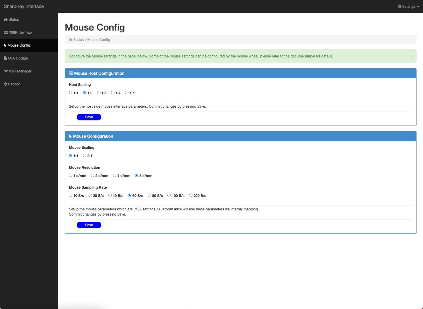
The Mouse Configuration screen shows 2 panels:
- A Mouse Host Configuration panel - this is used to configure host side mouse parameters.
- A Mouse PS/2 Configuration panel - this is used to configure PS/2 side mouse parameters.
Mouse Host Configuration
This panel currenly presents one option, setting the host side scaling of the PS/2 movement data. Select the scaling required and press the
Save button to commit to permanent storage. This feature can also be set via the mouse scroll wheel.
Mouse PS/2 Configuration
This panel offers 3 configurable options:
- PS/2 Mouse Scaling - This feature can scale the movement data sent by the mouse. If set to 1:1, no scaling occurs, if set to 2:1 then the movement data is multiplied by 2 resultion in the mouse movement been more rapid and travels further.
- PS/2 Mouse Resolution - This feature sets the accuracy of the mouse data as the mouse moves 1mm. The most inaccurate value is 1 c/mm, ie. 1 division value per mm, the most accurate is 8 c/mm, ie, 8 division values per mm.
- PS/2 Mouse Sampling Rate - This feature sets the accuracy of the mouse by transmitting more data per second regarding it's movement. The Sharp protocol requires a continous transmission of data every 20ms which equates to a sampling rate of 50/s, so a PS/2 sampling rate of 60/s is considered the optimal value.
After setting the required values, press the 'Save' button to commit the changes to permanent storage.
NB: The Mouse Configuration menu will be displayed when the SharpKey is primarily used as a mouse, ie. the Host cable connects to a Host mouse port. If the Host is keyboard and mouse capable over one cable then both the host keyboard map and mouse configuration menu will appear in the side-menu bar.
Credits
Espressif IDF development environment and use of the ESP-32S reference material was used in the design of this keyboard interface.
Licenses
This design, hardware and software, is licensed under the GNU Public Licence v3.
No commercial use to be made of this design or any hardware/firmware component without express permission from the author. This condition overrides
any rights afforded by the GNU GPL 3 license.
The Gnu Public License v3
The source and binary files in this project marked as GPL v3 are free software: you can redistribute it and-or modify it under the terms of the GNU General Public License as published by the Free Software Foundation, either version 3 of the License, or (at your option) any later version.
The source files are distributed in the hope that it will be useful, but WITHOUT ANY WARRANTY; without even the implied warranty of MERCHANTABILITY or FITNESS FOR A PARTICULAR PURPOSE. See the GNU General Public License for more details.
You should have received a copy of the GNU General Public License along with this program. If not, see http://www.gnu.org/licenses/.