 tranZPUter SW
Foreword
The tranZPUter SW is an offshoot from the tranZPUter project and utilises a Freescale K64F processor as the IO Control processor as opposed to the ZPU in the original tranZPUter project.
During testing of the tranZPUter v1.0 and with the advent of the RFS v2.0 upgrade with CP/M it was noticed that the tranZPUter should be updated so that the Z80 had additional memory and was able to run at higher clock frequencies. It should also run independent of the controlling IO processor, ie. the ZPU Evo on FPGA fabric or the K64F.
V1.0 of the tranZPUter had design restrictions which in all honesty make the project much harder to complete, for example, because of my lack of experience soldering BGA (Ball Grid Array) IC's, I chose the next best thing, a pre-fab FPGA board, the CYC1000 with the FPGA already soldered. This device and all other possibilities for the given size and FPGA ALM requirements had too few general I/O pins. This meant that multiplexing had to be used with tri-state register latches. KISS comes back to mind, Keep It Simple Stupid! So in order to further the concept and design I took a step back, looked at what was needed at the Z80 side to realise the CP/M requirements and looked at what was needed for the controlling IO Processor. As I am still not happy about soldering a 30+ pound IC where only an X-Ray machine can validate that it was soldered correctly, I opted for a powerful mini-development board, the Teensy 3.5 which has more than enough general I/O pins and is 5V tolerant, hence this interim design (which is actually better for anyone who is a software programmer and is not happy with electronics or VHDL yet wants to enhance a Z80 machine).
Everything will be written in C/C++ (FLW - Famous Last Words - I had to write the interrupt service routines in ARM Thumb assembler as the K64F isnt quite powerful enough using compiled C) and once working, I can take the bold step into speccing a tranZPUter v2.0 with a BGA knowing that the ZPU will run all the software just written.
Overview
The upgrade also extends the Z80 hardware capabilities by providing additional RAM to allow for a 64K version of CP/M and to increase the speed of the processor whilst maintaining the original speed when accessing the Sharp MZ80A motherboard peripherals.
This design is a work in progress, working in tandem with the tranZPUter. The C/C++ control software written for the tranZPUter SW is intended to work on the tranZPUter under the ZPU.
As the design replaces a Z80 in-situ it is not limited to the MZ80A but can be used in any Z80 based computer with the right software adaptations, ie. the MZ-700 or MZ-80B.
tranZPUter SW
The tranZPUter SW follows on from the tranZPUter design in it's goals and makes an improvement on the underlying Z80 hardware at the same time. It uses a Freescale K64F ARM Cortex-M4 in place of the ZPU Evo as the tranZPUter SW is more a software solution to the requirement rather than the ZPU Evo which is based on VHDL on an FPGA. The project adds the suffix SW for *S*oft*W*are to distinguish the two designs.
To provide different CPU's it is just a matter of taking existing CPU emulators, for example those used in the PiCoPro and adapting them to use the CPU signals on the MZ80A bus via this designs interface. The program memory could either be that on the MZ80A or the faster K64F memory. ie. There is no real need to use the MZ80A memory when using a soft CPU. The benefits of using a soft CPU is potentially better performance albeit this is yet to be determined as the K64F only runs at 120MHz. The design of the tranZPUter SW upgrades the Z80 hardware and can clock the processor, detached from the Sharp MZ80A motherboard, at much higher clock rates, potentially to 20MHz using the Z8400 20MHz CPU. Higher CPU performance will be a benefit to programs such as CP/M or databases such as DBase II.
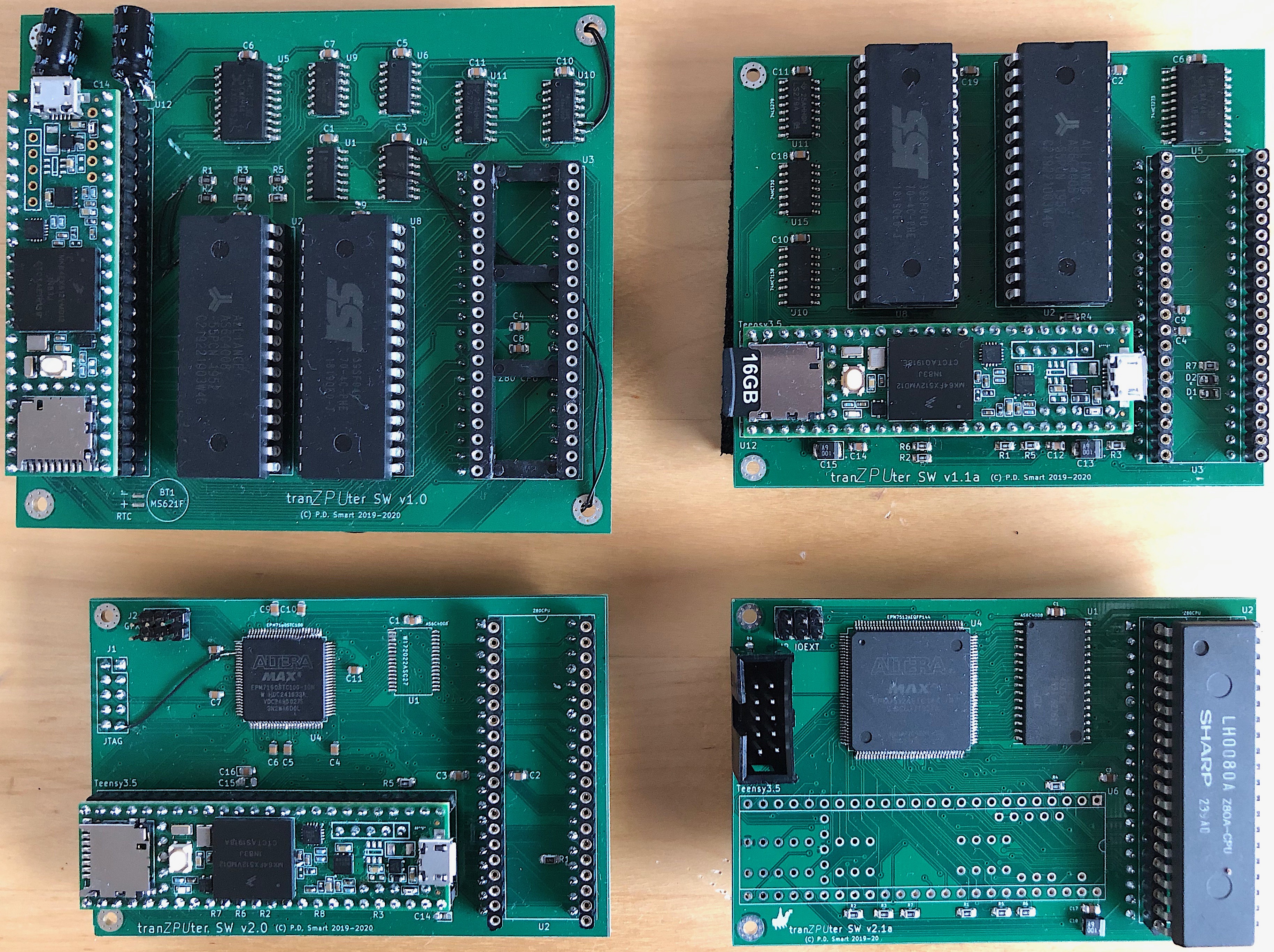
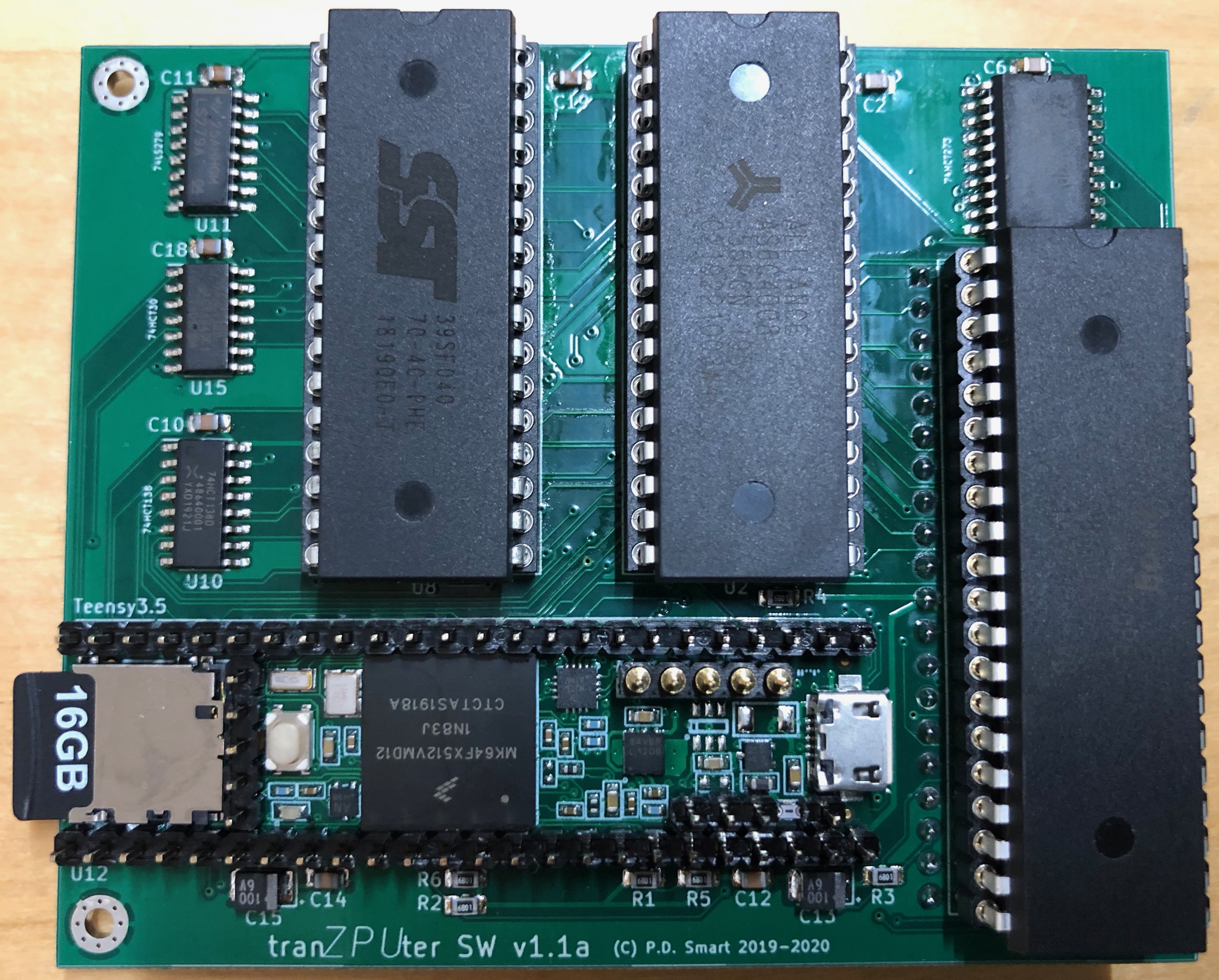
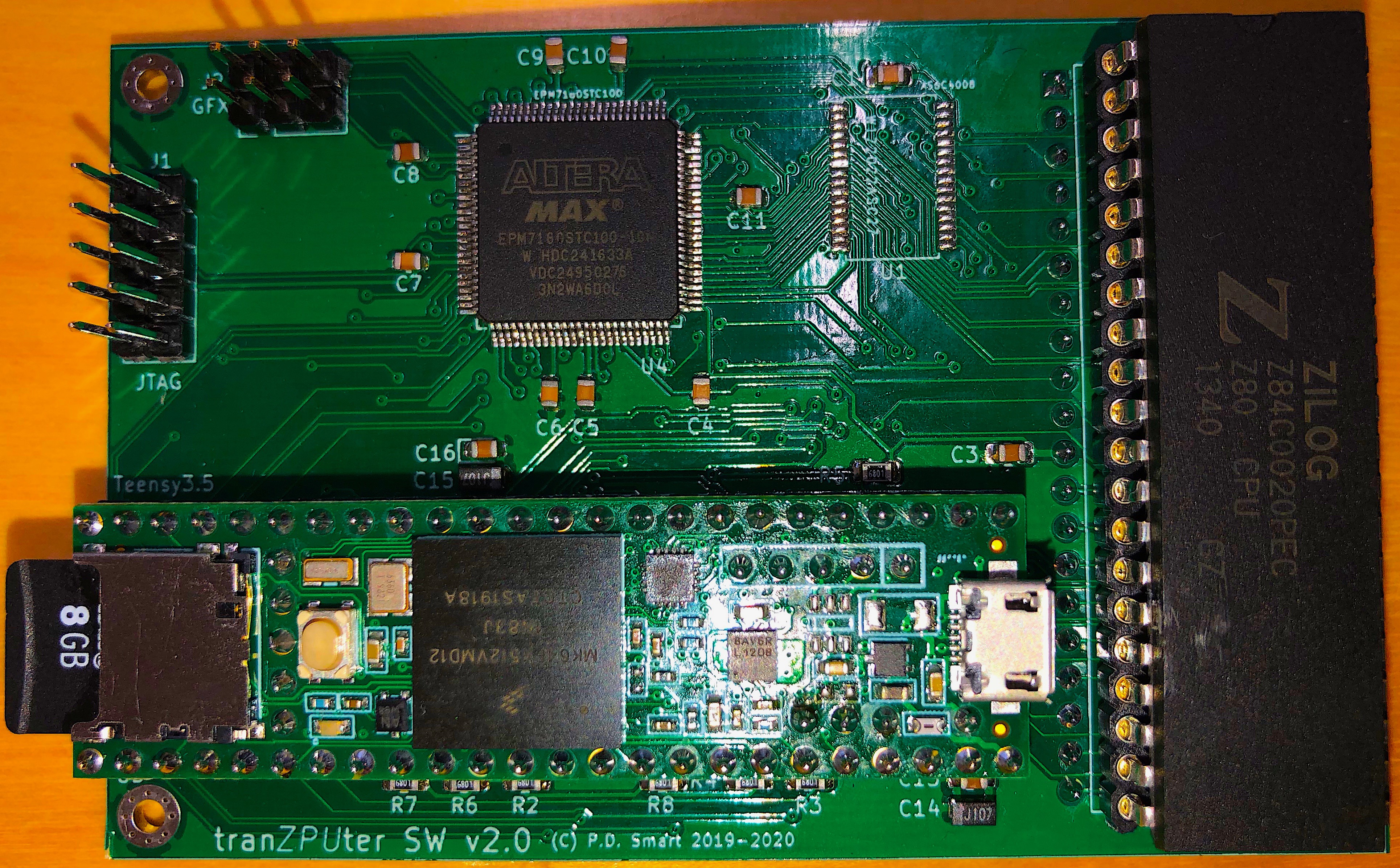
In the gallery are pictures of the current design and files uploaded onto github are relatively stable, WIP files wont be uploaded as they are in constant flux.
Hardware
Bus mastering is used to take control of the Z80 bus and to transfer data between main memory and an SD Card or between the I/O processor and the Video display buffer for presentation of menu's. It is also used where a soft processor completely idle's the hard Z80 and acts as the main computer CPU. ie. using a soft CPU emulator, it can process applications in local memory and slow down to access I/O and the Video buffer on the host machine as needed presenting a completely different computing experience. Imagine, a 6809 or a 68000 based Sharp MZ80A!
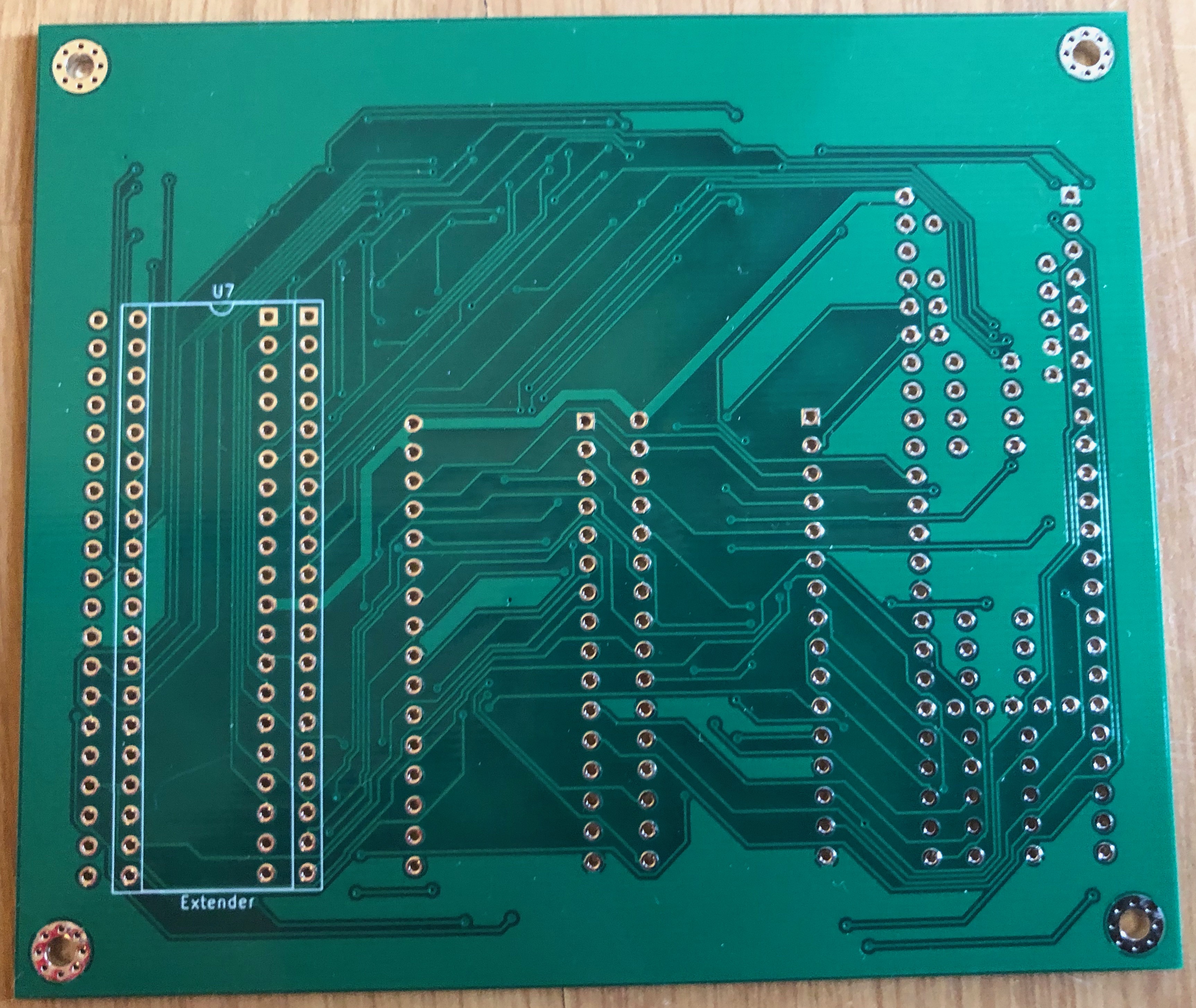
The design centres around lifting the original Z80 onto a daughter card and rerouting several of its signals such that they can be controlled as needed.
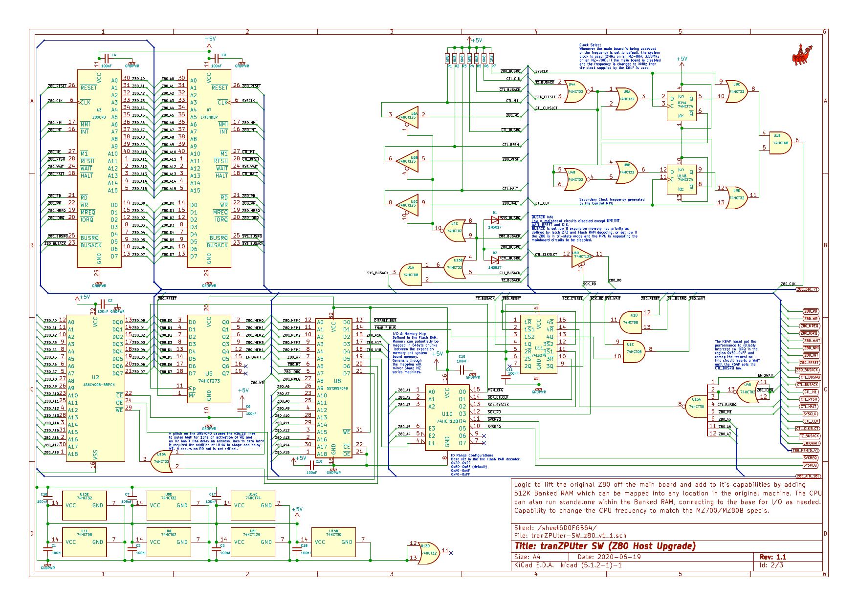
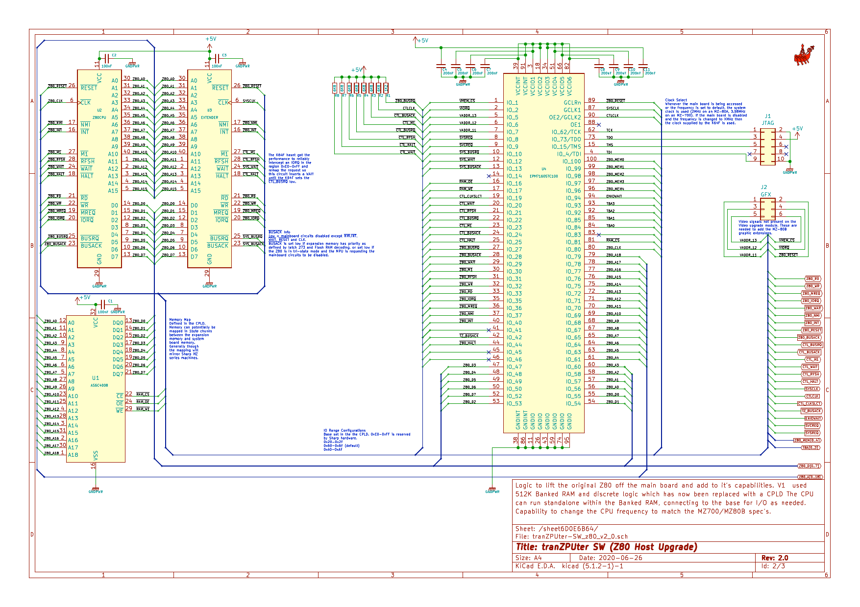
v1.0 Z80 Upgrade Schematic
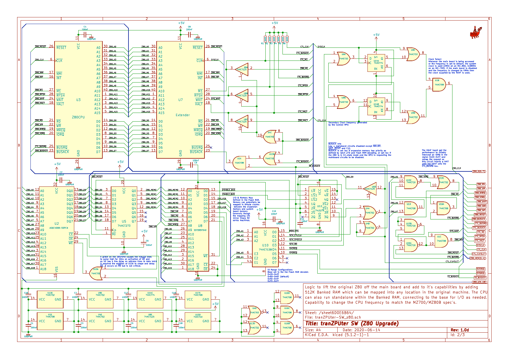
The above schematic has been designed such that the basic board can be installed without an IO processor, just plug this board into the Z80 socket on the Sharp MZ80A and it runs as standard and the additional features can be accessed programaticaly in BASIC/Assembler. If the RFS board has been installed then an update to the RFS software will make use of the additional enhanced hardware features. If the RFS board has not been installed and you add the IO Control processor (a Teensy 3.5) then a whole new range of options becomes available which match and exceed those available with the RFS board. Using this design it will be easier to use an FPGA in place of the Teensy 3.5 for the final tranZPUter project.
As the project has progressed small changes have been made to the first cut PCB to reflect fixes and enhancements. The above revision, 1.0d adds extra logic which on the prototype PCB is realised with p-p wiring and piggyback IC's. The design fully works now and version 1.1 will see logic reduction as far as possible but keep the use of discrete logic rather than a GAL/PAL. Version 1.1 will also use more SMD devices to shrink the PCB size such that it will fit inside the casing of the MZ-80A, MZ-80B and MZ-700. A future version 2 will see the removal of all discrete logic and the 512KB Flash RAM decoder and be replaced with a CPLD.
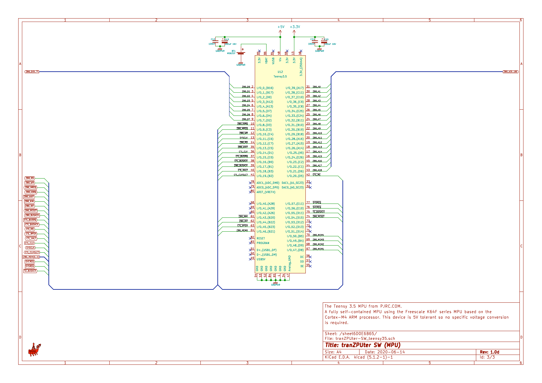
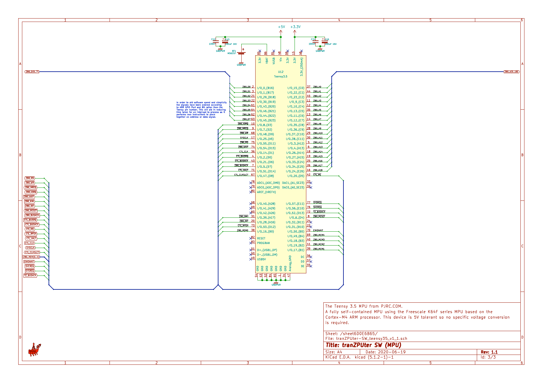
v1.0 Teensy 3.5 Schematic
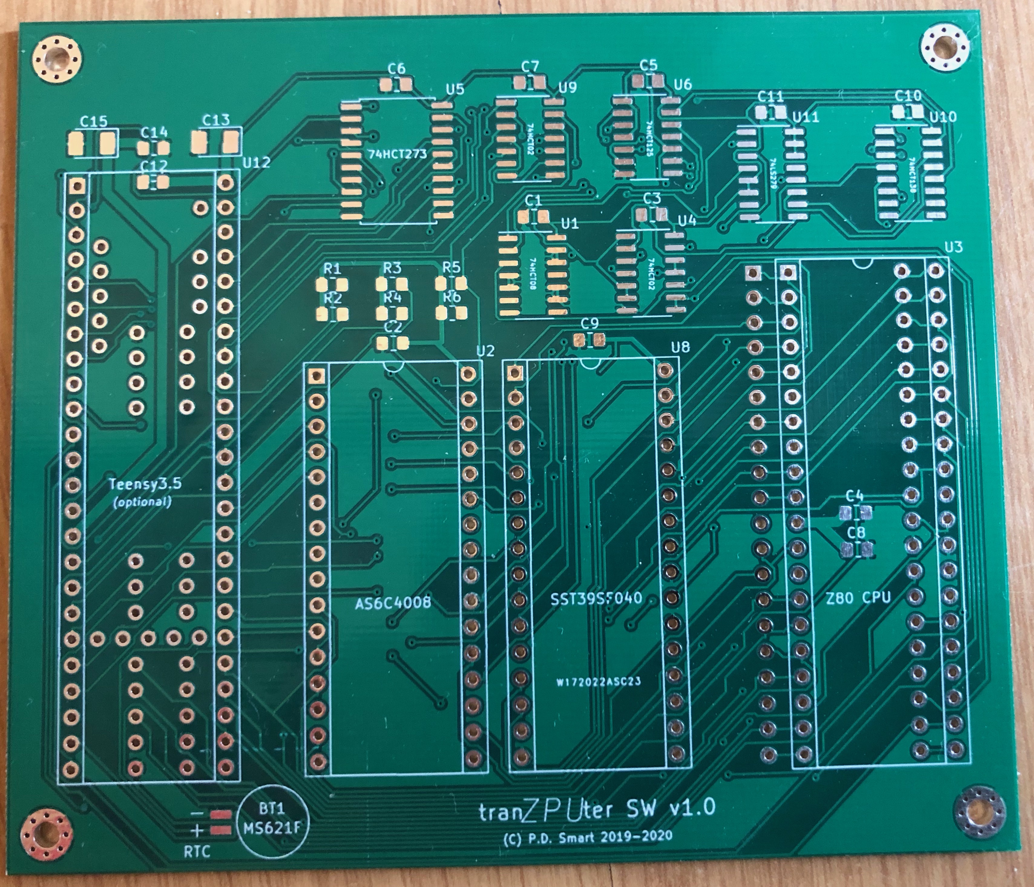
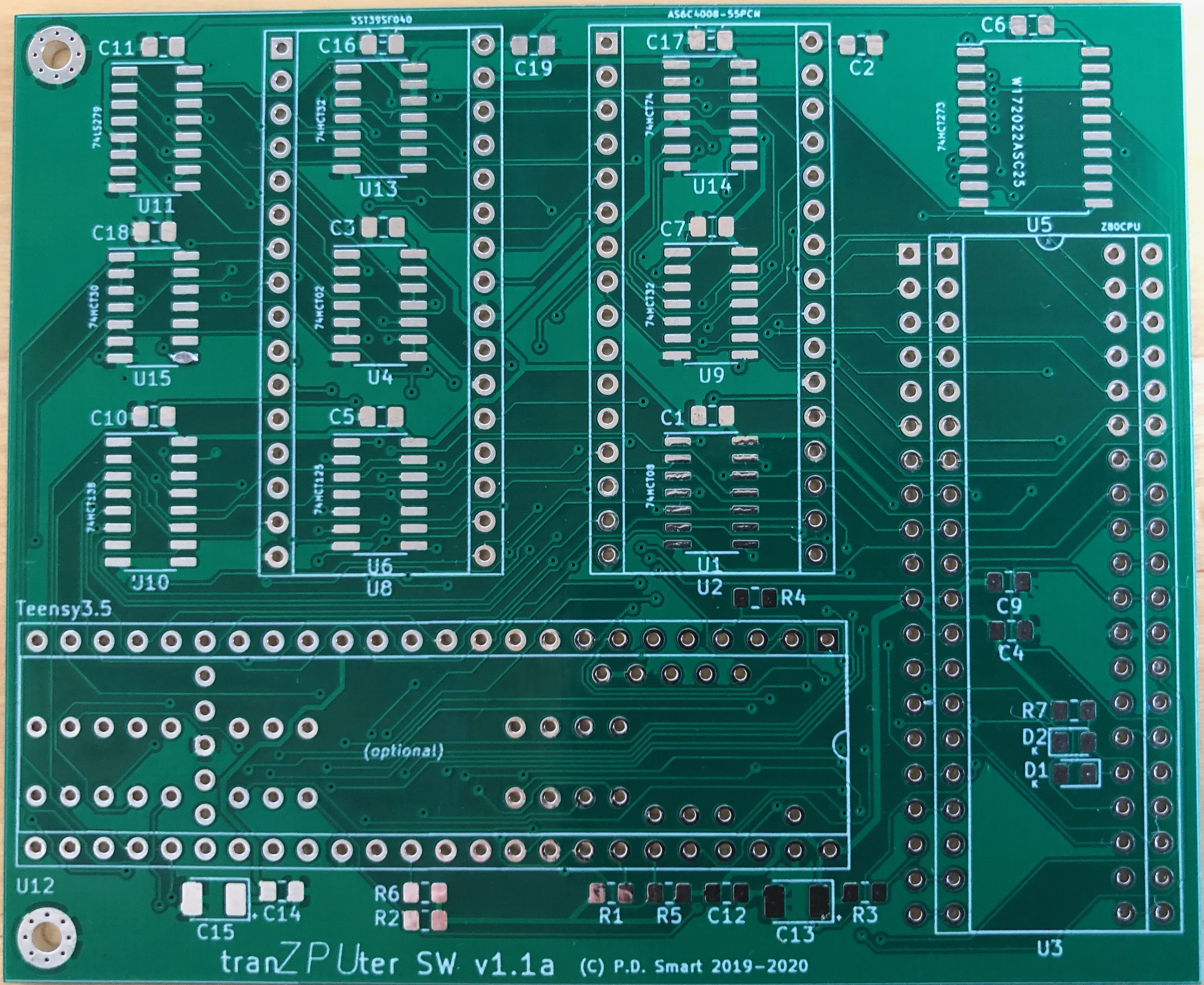
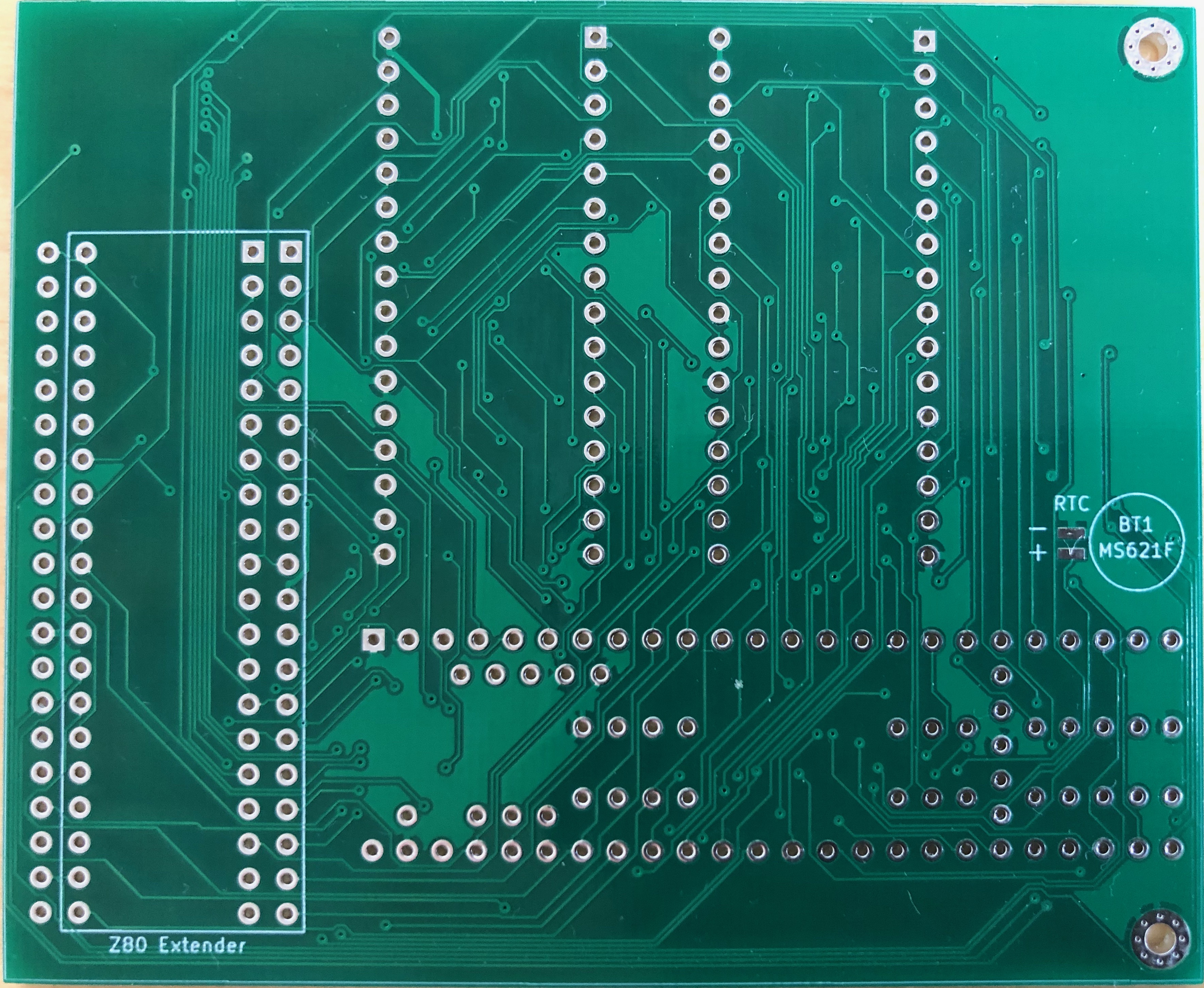
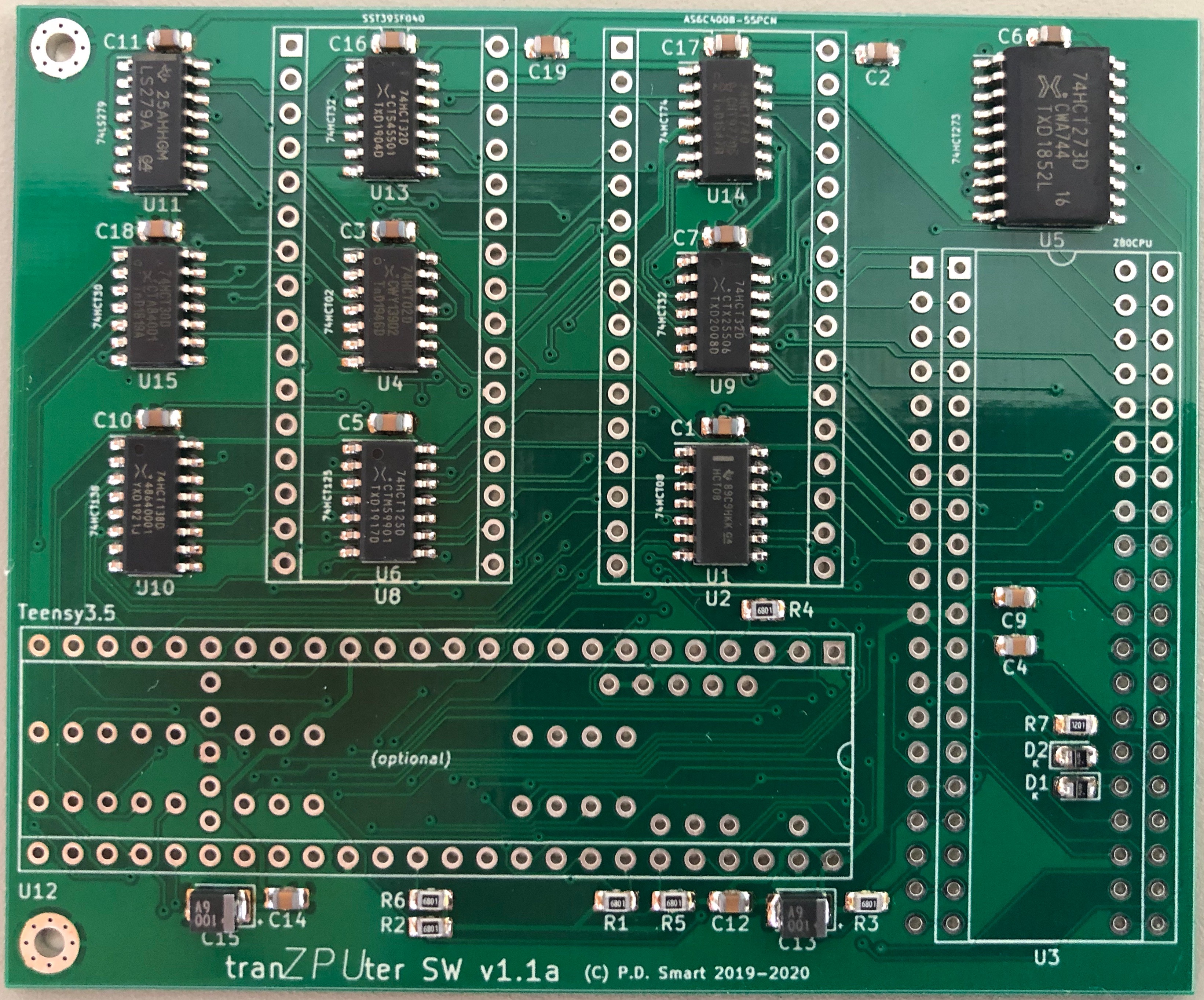
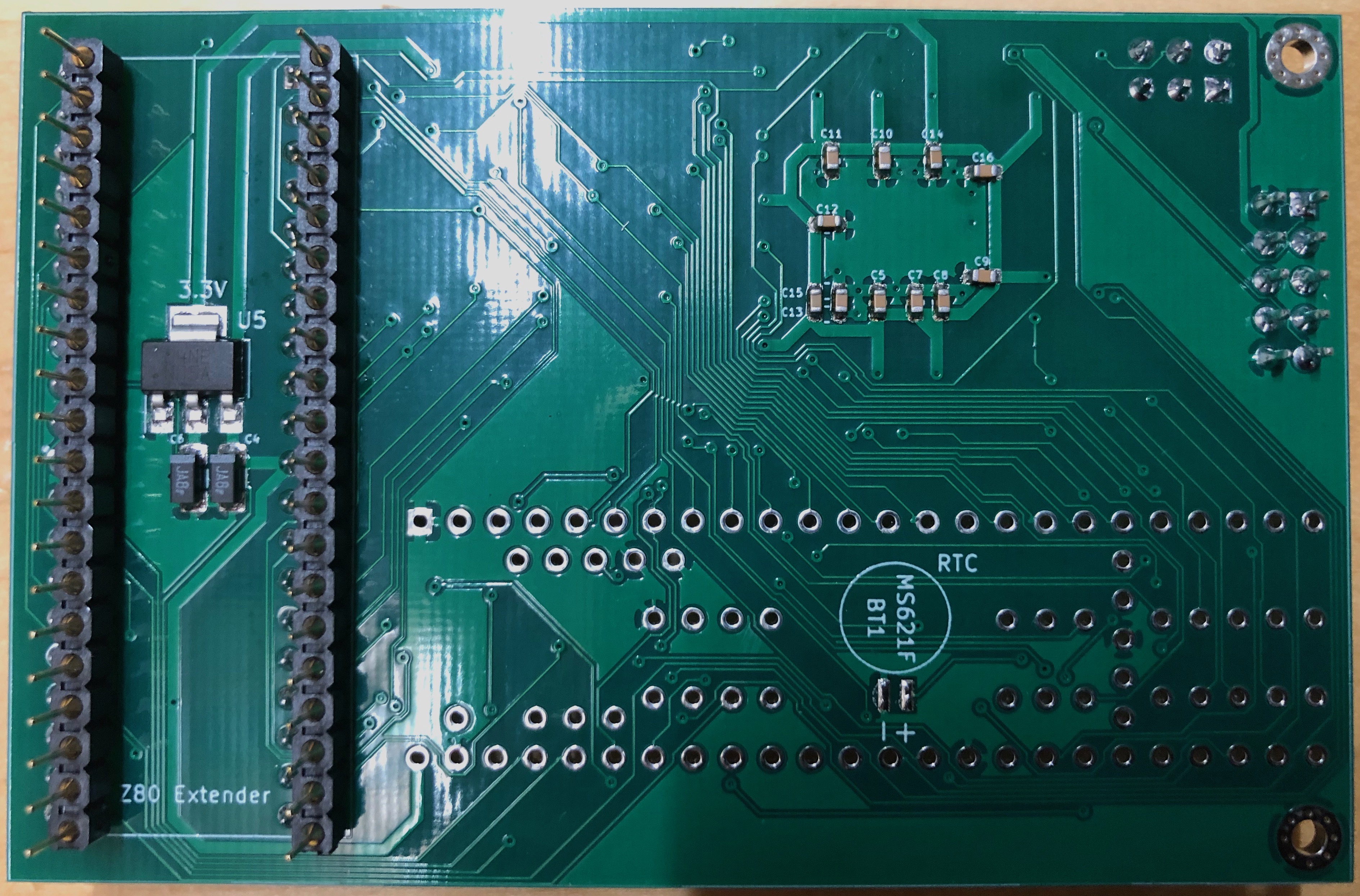
v1.0 PCB
As per previous schematics and PCB boards, this project has been designed with KiCad Schematic Capture and PCB Layout. Below are the finished boards awaiting components and assembly.
v1.1 Z80 Upgrade Schematic
v1.1 Teensy 3.5 Schematic
Version 1.1 is very similar to v1.0d, just adding of ENIOWAIT to detect when the wait state generator is enabled.
v1.1 PCB
Version 1.1 of the PCB compacts the design a little. I was hoping to make 1 board to fit both the Sharp MZ-80A and MZ-700 but the restrictions placed on the PCB by the MZ-700 (opposite way Z80, gap to insert/remove SD card, clearance etc) means two boards will need to be designed.
The board below is the Kicad image of the Sharp MZ-80A board which is currently being manufactured, the version 1.1 design and PCB is just an iterative design given all the changes needed from v1.0 -> v1.0d.
v2.0 Z80 Upgrade Schematic
v2.0 Teensy 3.5 Schematic
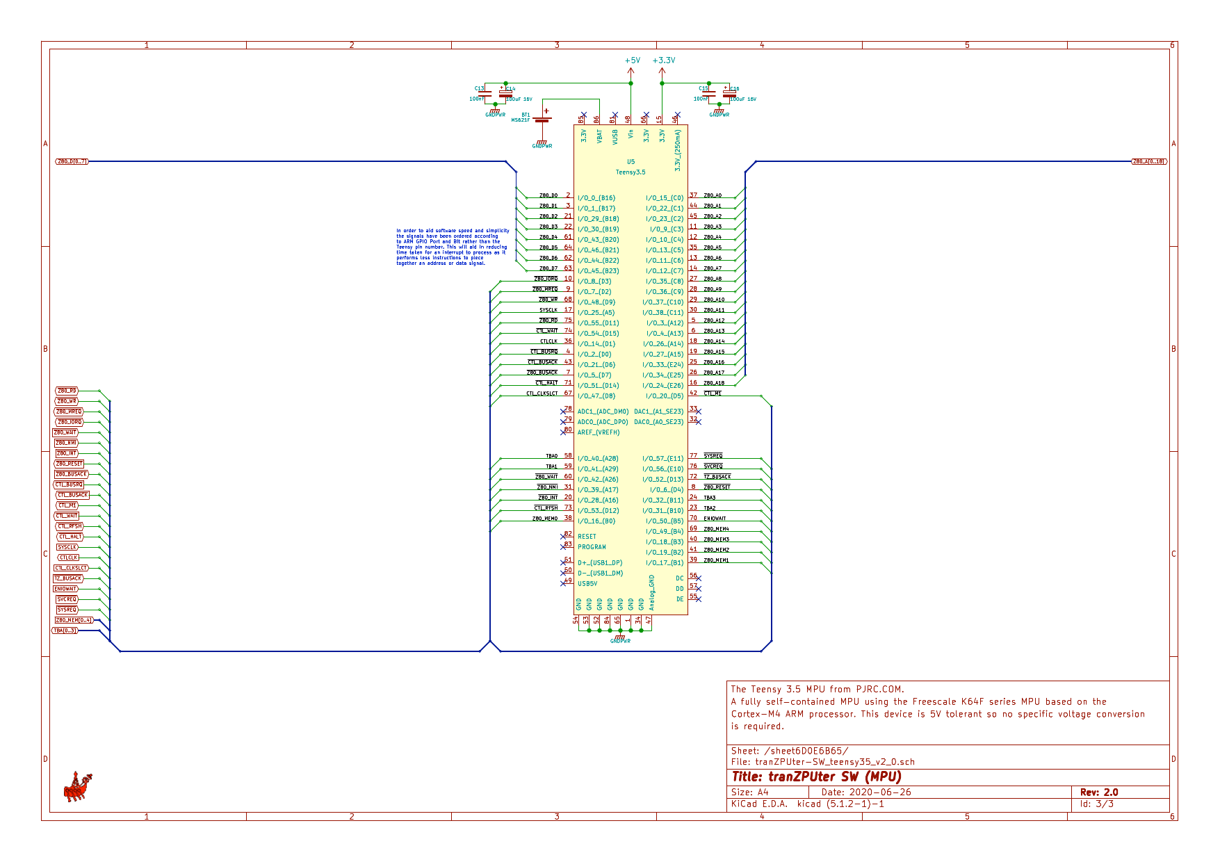
Version 2.0 is very similar to v1.1, just adding additional connectivity as the list of ideas grow.
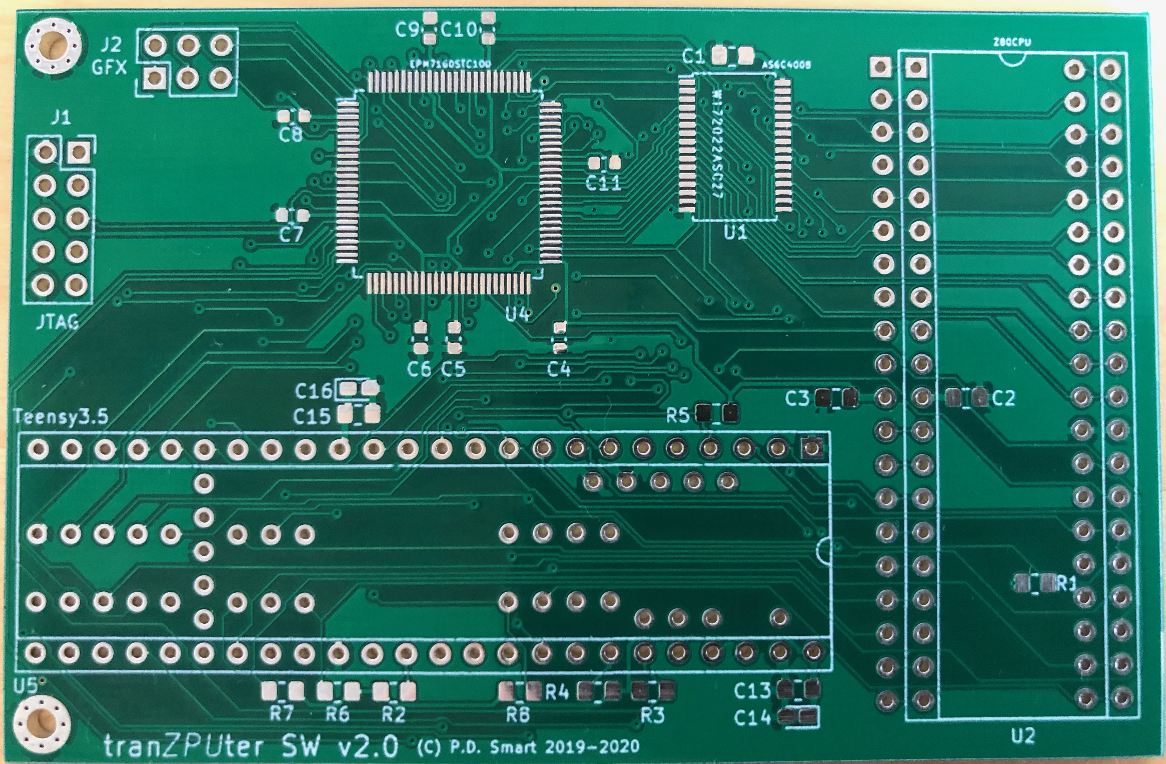
v2.0 PCB
Version 2.0 of the PCB compacts the design quite a bit. It is still not so easy to make one board to fit both the Sharp MZ-80A and MZ-700 unless I go to 4 layer which is the intention when the project reaches maturity.
The board below is the Kicad image of the Sharp MZ-80A board which has been manufactured and partly assembled. I made a real blunder on this board and still wondering how I did it!!! I wanted to use the AS6C4008 sTSOP device to minimise space and ended up with the TSSOP, probably late nights but the fact I never spotted the blunder until I actually ordered the parts means I need to change tact and order parts as I design the board to minimise this kind of mistake.
v2.1 Z80 Upgrade Schematic
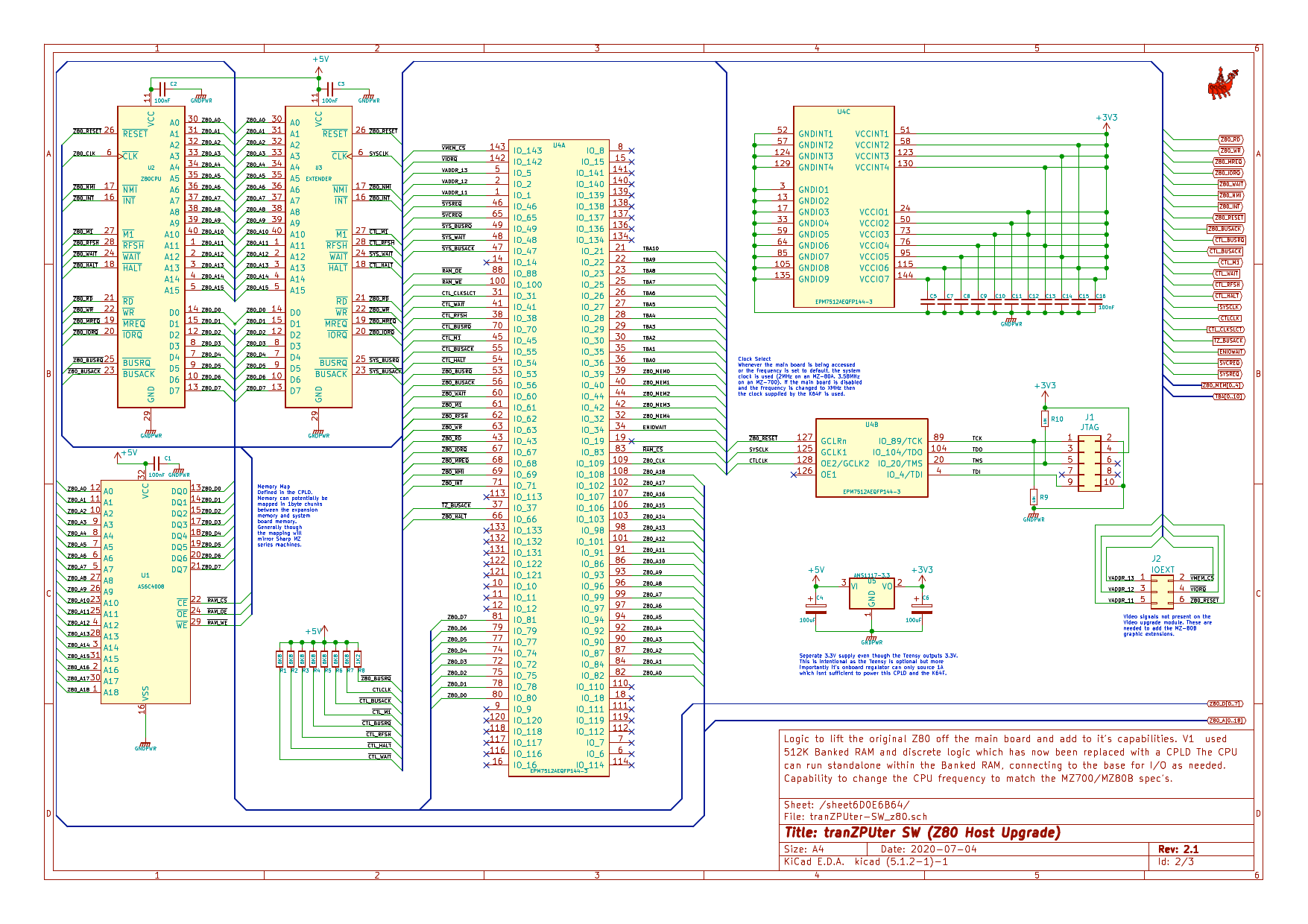
v2.1 Teensy 3.5 Schematic
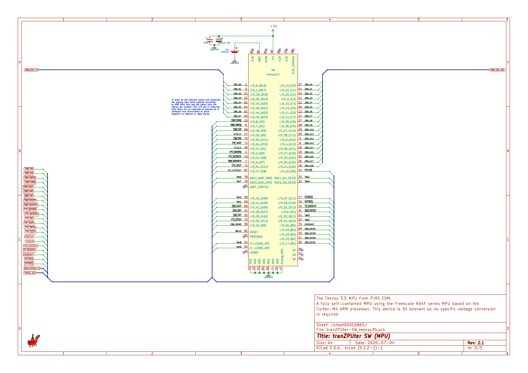
Version 2.1 is very similar to v2.0, just adding even more connectivity especially as we are operating at 3.3V now as the K64F isnt 5V tolerant on all pins.
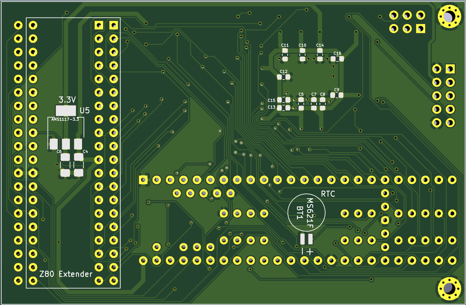
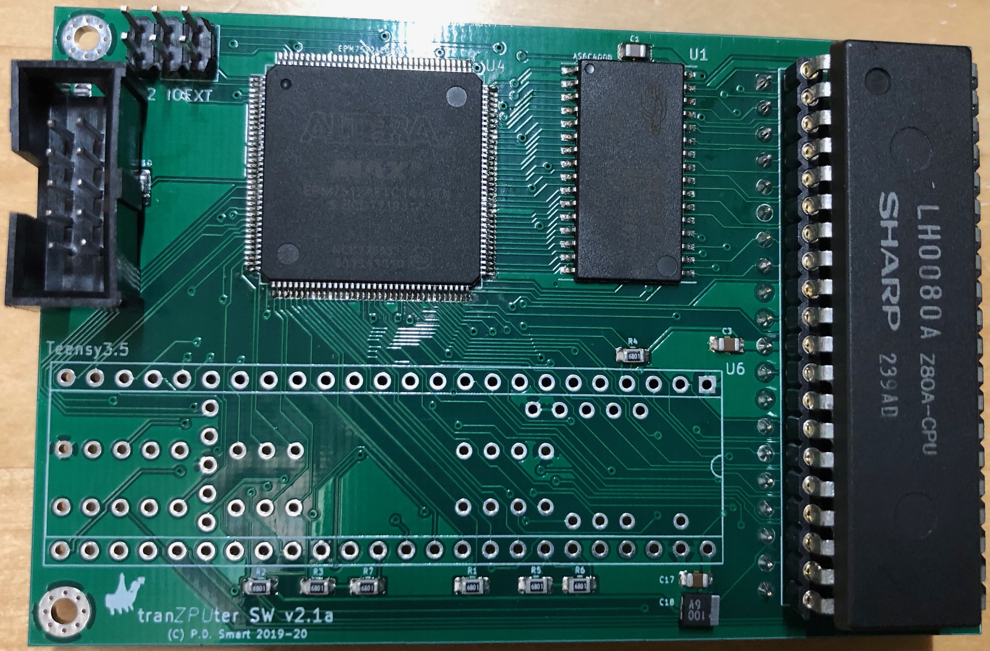
v2.1 PCB
Version 2.1 of the PCB follows on from v2.0 using higher density TQFP packaging and the Correct! SRAM package, which is now correctly specc'd as TSOP and ordered. TSOP was chosen rather than sTTSOP due to PCB routing, it proved quite a challenge with the narrower pins.
The board below is the Kicad image of the PCB for the Sharp MZ-80A.

v2.2 Z80 Upgrade Schematic
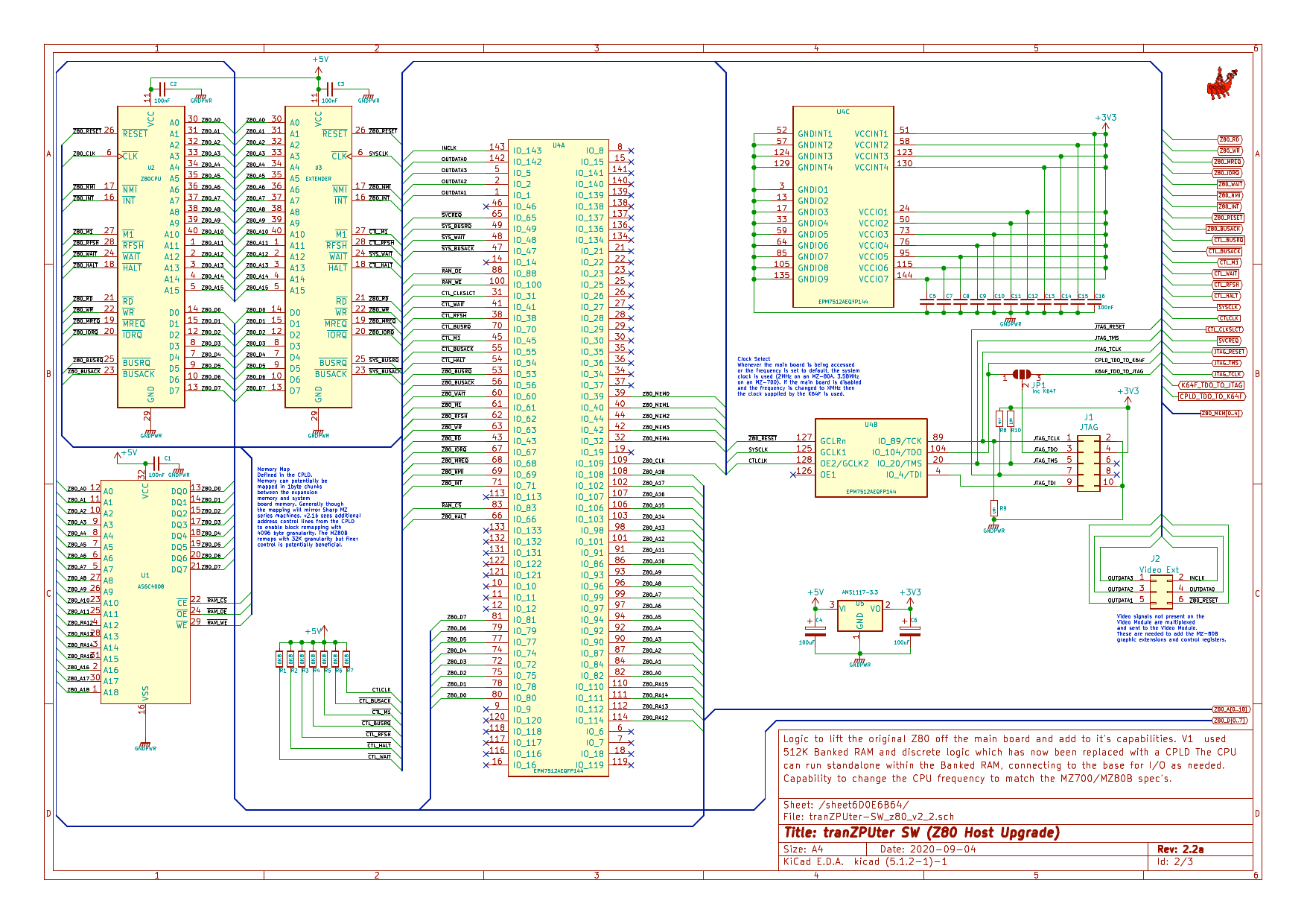
For compatibility, if needed, the Teensy 3.5 bootstrap MCU can be optionally installed otherwise programming is achieved via the JTAG interface.
v2.2 The K64 I/O Processor
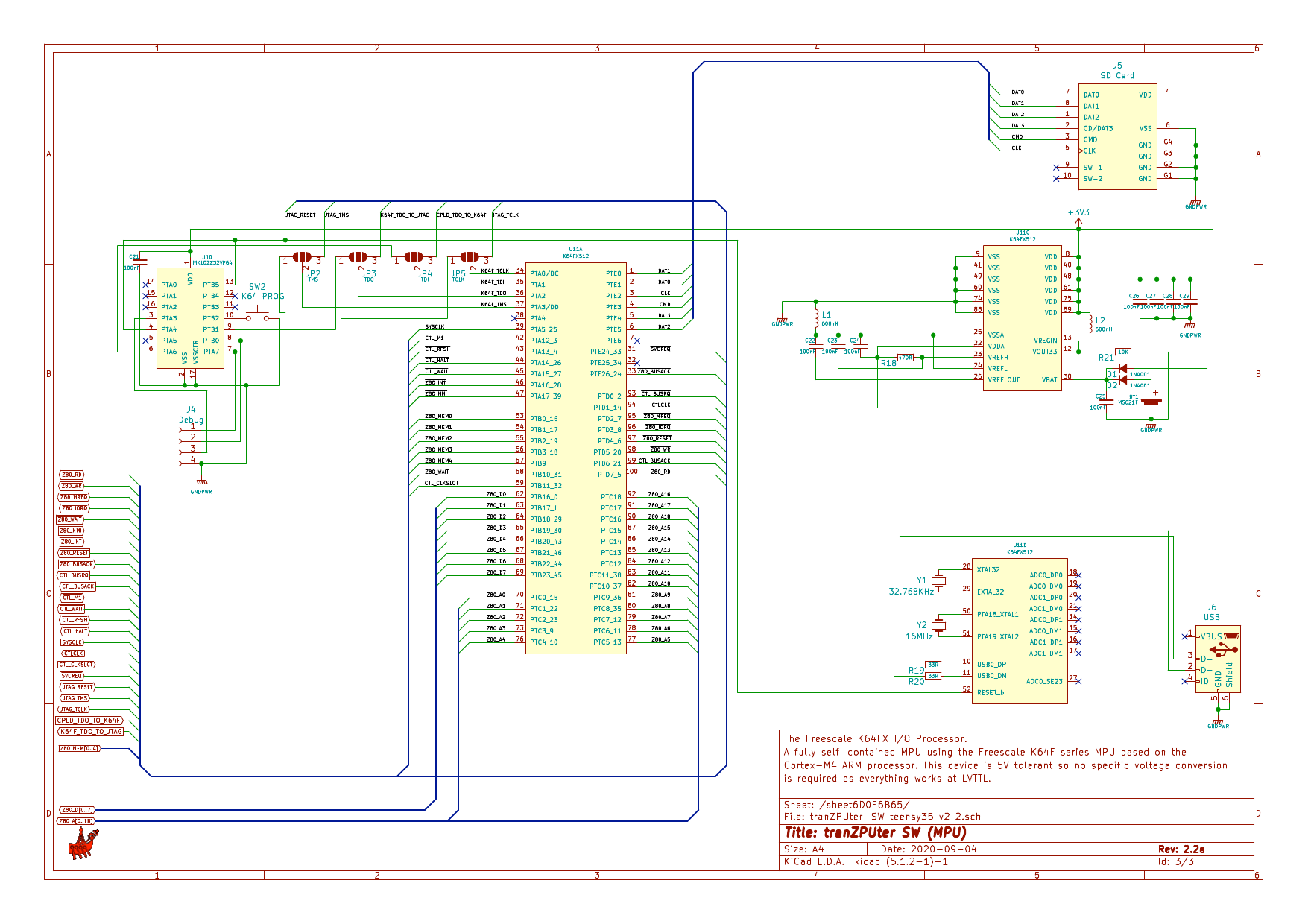
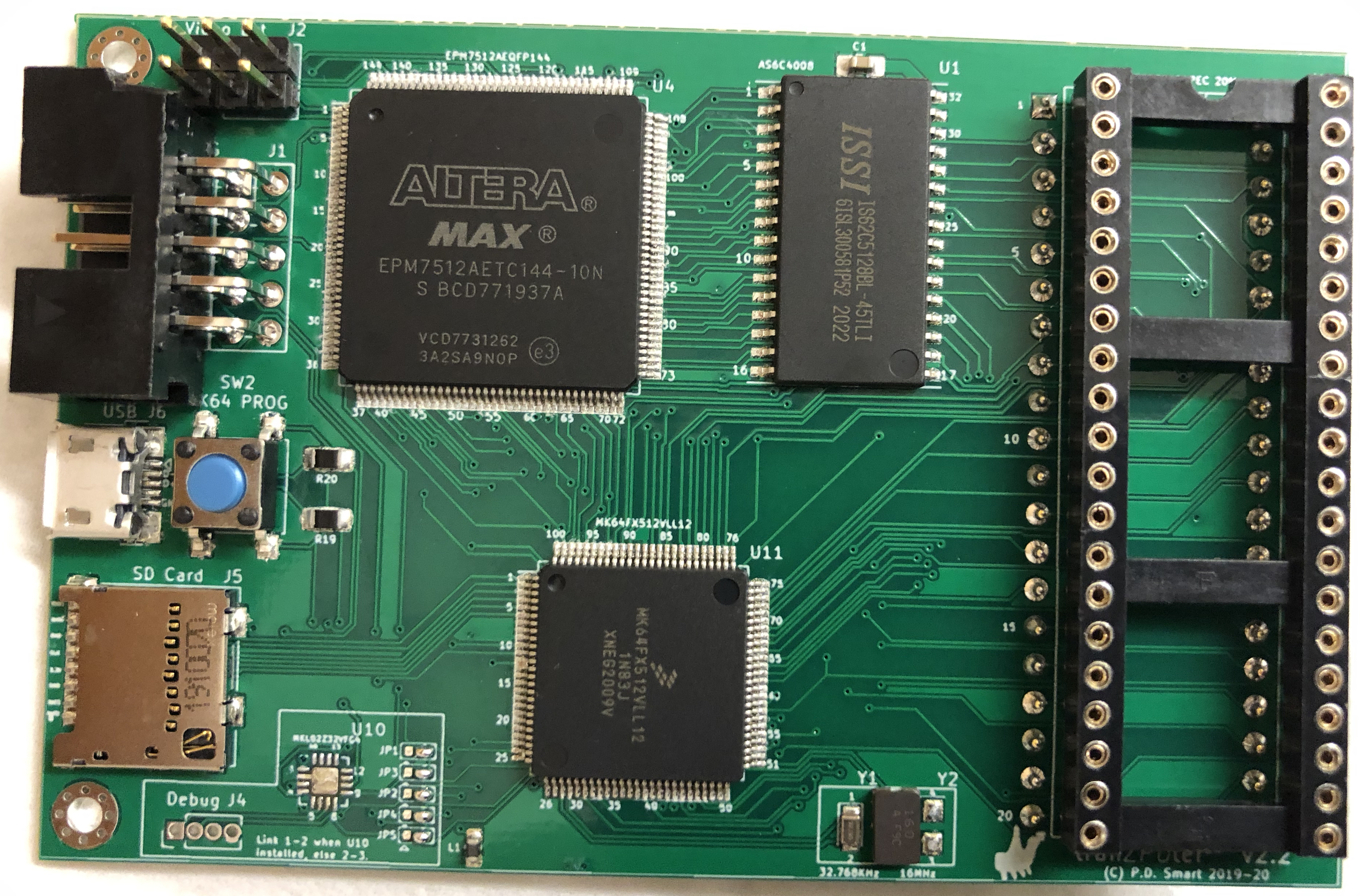
Version 2.2 replaces the Teensy 3.5 development board with a 100pin QFP MK64FX512 processor and the ability to optionally add a Teensy bootstrap MCU for ease of programming if needed.
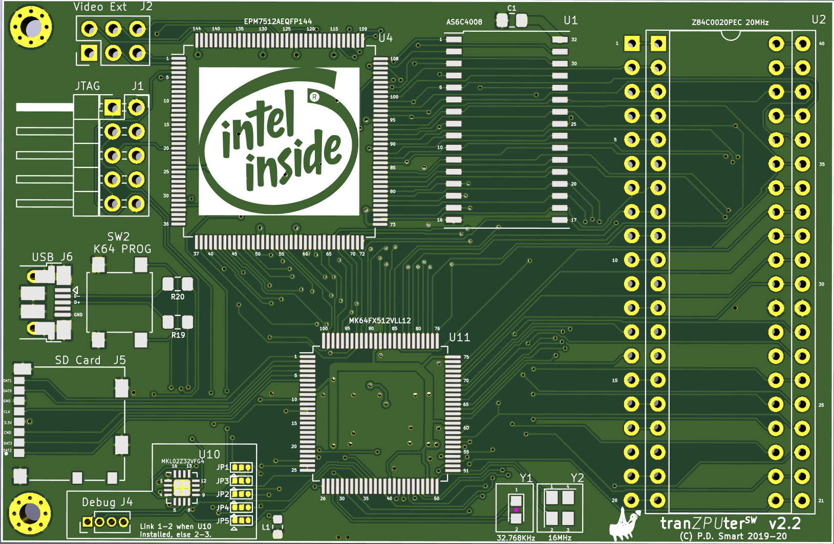
v2.2 PCB
Version 2.2 of the PCB follows on from v2.1 using higher density TQFP packaging and places a forward facing SD Card and micro USB type B interface for ease of access.
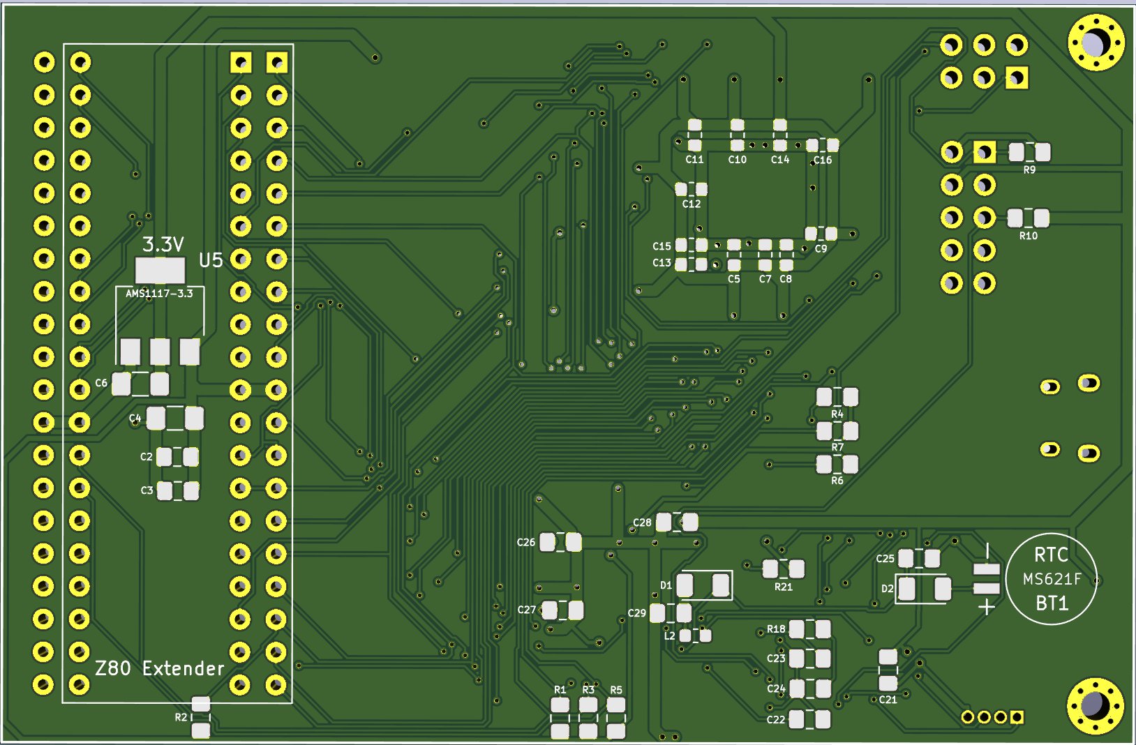
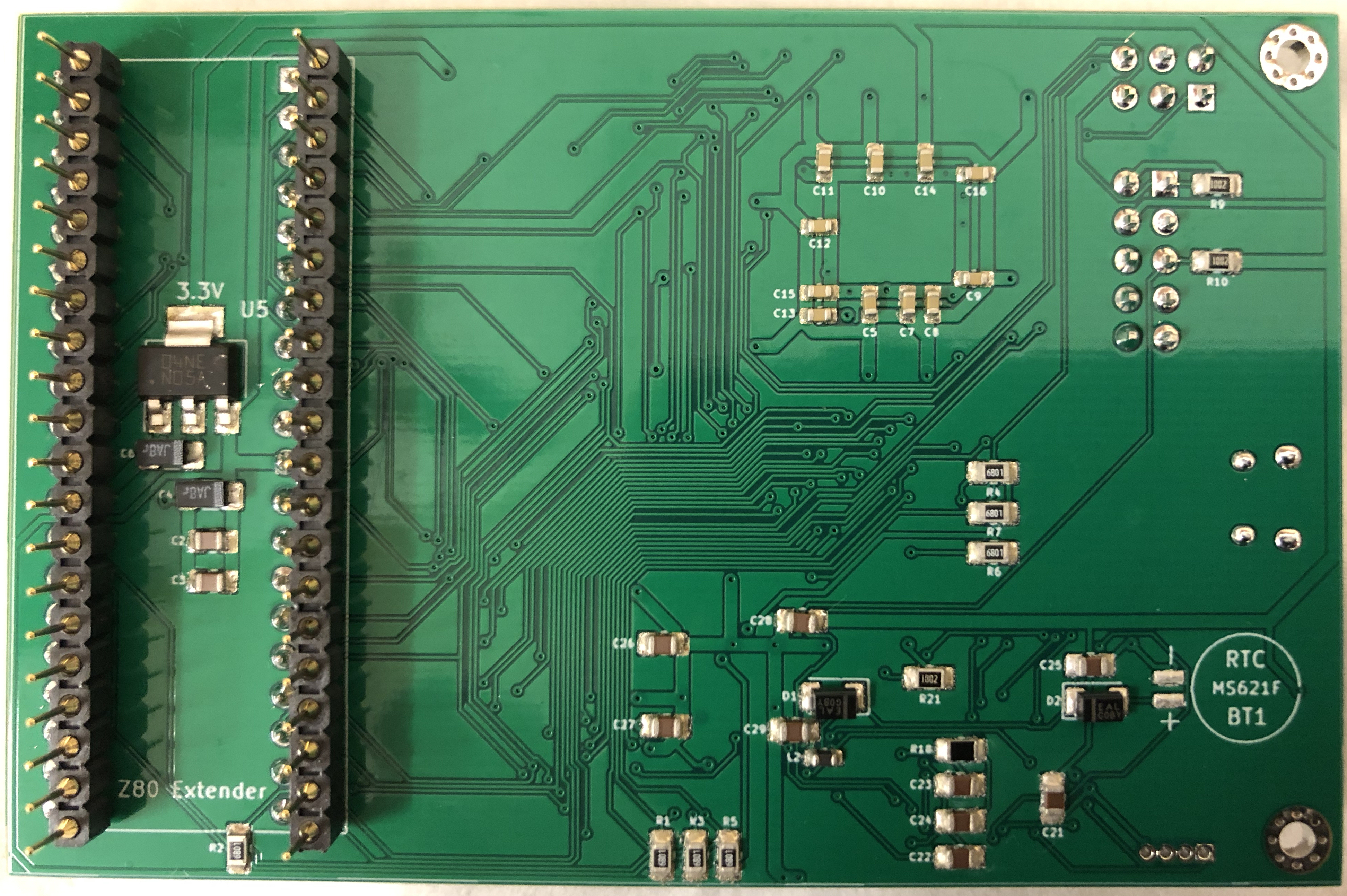
The board below is the Kicad image of the PCB for the Sharp MZ-80A, designed in Kicad and sent out for manufacture.
Design Detail
K64F Z80 Host API
// Structure to contain inter CPU communications memory for command service processing and results.
// Typically the z80 places a command into the structure in it's memory space and asserts an I/O request,
// the K64F detects the request and reads the lower portion of the struct from z80 memory space,
// determines the command and then either reads the remainder or writes to the remainder. This struct
// exists in both the z80 and K64F domains and data is sync'd between them as needed.
//
typedef struct __attribute__((__packed__)) {
    uint8_t                          cmd;                                // Command request.
    uint8_t                          result;                             // Result code. 0xFE - set by Z80, command available, 0xFE - set by K64F, command ack and processing. 0x00-0xF0 = cmd complete and result of processing.
    union {
        uint8_t                      dirSector;                          // Virtual directory sector number.
        uint8_t                      fileSector;                         // Sector within open file to read/write.
        uint8_t                      vDriveNo;                           // Virtual or physical SD card drive number.
    };
    union {
        struct {
            uint16_t                 trackNo;                            // For virtual drives with track and sector this is the track number
            uint16_t                 sectorNo;                           // For virtual drives with track and sector this is the sector number. NB For LBA access, this is 32bit and overwrites fileNo/fileType which arent used during raw SD access.
        };
        uint32_t                     sectorLBA;                          // For LBA access, this is 32bit and used during raw SD access.
    };
    uint8_t                          fileNo;                             // File number of a file within the last directory listing to open/update.
    uint8_t                          fileType;                           // Type of file being processed.
    union {
        uint16_t                     loadAddr;                           // Load address for ROM/File images which need to be dynamic.
        uint16_t                     saveAddr;                           // Save address for ROM/File images which need to be dynamic.
        uint16_t                     cpuFreq;                            // CPU Frequency in KHz - used for setting of the alternate CPU clock frequency.
    };
    union {
        uint16_t                     loadSize;                           // Size for ROM/File to be loaded.
        uint16_t                     saveSize;                           // Size for ROM/File to be saved.
    };
    uint8_t                          directory[TZSVC_DIRNAME_SIZE];      // Directory in which to look for a file. If no directory is given default to MZF.
    uint8_t                          filename[TZSVC_FILENAME_SIZE];      // File to open or create.
    uint8_t                          wildcard[TZSVC_WILDCARD_SIZE];      // A basic wildcard pattern match filter to be applied to a directory search.
    uint8_t                          sector[TZSVC_SECTOR_SIZE];          // Sector buffer generally for disk read/write.
} t_svcControl;
Communications are all instigated by the Z80. When it needs a service, it will write a command into the svcControl.cmd field and set the svcControl.result field to REQUEST. The Z80 then writes to an output port (configurable but generally 0x68) which in turn sends an interrupt to the K64F. The K64F reads the command and sets the svcControl.result to PROCESSING - the Z80 waits for this handshake, if it doesnt see it after a timeout period it will resend the command. The Z80 then waits for a valid result, again if it doesnt get a result in a reasonable time period it retries the sequence and after a number of attempts gives up with an error.
Once the K64F has processed the command (ie. read directory) and stored any necessary data into the structure, it sets the svcControl.result to a valid result (success, fail or error code) to complete the transaction.
API Command List
| Command | Cmd# | Description |
|---|---|---|
| TZSVC_CMD_READDIR | 0x01 | Open a directory and return the first block of entries. |
| TZSVC_CMD_NEXTDIR | 0x02 | Return the next block in an open directory. |
| TZSVC_CMD_READFILE | 0x03 | Open a file and return the first block. |
| TZSVC_CMD_NEXTREADFILE | 0x04 | Return the next block in an open file. |
| TZSVC_CMD_WRITEFILE | 0x05 | Create a file and save the first block. |
| TZSVC_CMD_NEXTWRITEFILE | 0x06 | Write the next block to the open file. |
| TZSVC_CMD_CLOSE | 0x07 | Close any open file or directory. |
| TZSVC_CMD_LOADFILE | 0x08 | Load a file directly into tranZPUter memory. |
| TZSVC_CMD_SAVEFILE | 0x09 | Save a file directly from tranZPUter memory. |
| TZSVC_CMD_ERASEFILE | 0x0a | Erase a file on the SD card. |
| TZSVC_CMD_CHANGEDIR | 0x0b | Change active directory on the SD card. |
| TZSVC_CMD_LOAD40ABIOS | 0x20 | Request 40 column version of the SA1510 BIOS to be loaded, change frequency to match the Sharp MZ-80A. |
| TZSVC_CMD_LOAD80ABIOS | 0x21 | Request 80 column version of the SA1510 BIOS to be loaded, change frequency to match the Sharp MZ-80A. |
| TZSVC_CMD_LOAD700BIOS40 | 0x22 | Request 40 column version of the 1Z-013A MZ-700 BIOS to be loaded, change frequency to match the Sharp MZ-700 and action memory page commands. |
| TZSVC_CMD_LOAD700BIOS80 | 0x23 | Request 80 column version of the 1Z-013A MZ-700 BIOS to be loaded, change frequency to match the Sharp MZ-700 and action memory page commands. |
| TZSVC_CMD_LOAD80BIPL | 0x24 | Request the loading of the MZ-80B IPL, switch frequency and enable Sharp MZ-80B compatible mode. |
| TZSVC_CMD_LOADBDOS | 0x30 | Reload CPM BDOS+CCP. |
| TZSVC_CMD_ADDSDDRIVE | 0x31 | Attach a CPM disk to a drive number. |
| TZSVC_CMD_READSDDRIVE | 0x32 | Read an attached SD file as a CPM disk drive. |
| TZSVC_CMD_WRITESDDRIVE | 0x33 | Write to a CPM disk drive which is an attached SD file. |
| TZSVC_CMD_CPU_BASEFREQ | 0x40 | Set the tranZPUter to use the mainboard frequency for the Z80. |
| TZSVC_CMD_CPU_ALTFREQ | 0x41 | Switch the Z80 to use the K64F generated clock, ie. alternative frequency. |
| TZSVC_CMD_CPU_CHGFREQ | 0x42 | Change the Z80 frequency generated by the K64F to the Hertz value given in svcControl.cpuFreq, the Z80 will be clocked at the nearest timer resolution of this frequency. |
| TZSVC_CMD_CPU_SETZ80 | 0x50 | Switch to the external Z80 hard cpu. |
| TZSVC_CMD_CPU_SETT80 | 0x51 | Switch to the internal T80 soft cpu. |
| TZSVC_CMD_CPU_SETZPUEVO | 0x52 | Switch to the internal ZPU Evolution cpu. |
| TZSVC_CMD_SD_DISKINIT | 0x60 | Initialise and provide raw access to the underlying SD card. |
| TZSVC_CMD_SD_READSECTOR | 0x61 | Provide raw read access to the underlying SD card. |
| TZSVC_CMD_SD_WRITESECTOR | 0x62 | Provide raw write access to the underlying SD card. |
| TZSVC_CMD_EXIT | 0x7F | Terminate TZFS and restart the machine in original mode. |
API Result List
| Command | Result# | Description |
|---|---|---|
| TZSVC_STATUS_OK | 0x00 | The K64F processing completed successfully. |
| TZSVC_STATUS_FILE_ERROR | 0x01 | A file or directory error. |
| TZSVC_STATUS_BAD_CMD | 0x02 | Bad service command was requested. |
| TZSVC_STATUS_BAD_REQ | 0x03 | Bad request was made, the service status request flag was not set. |
| TZSVC_STATUS_REQUEST | 0xFE | Z80 has posted a request. |
| TZSVC_STATUS_PROCESSING | 0xFF | K64F is processing a command. |
API Result List
| Command | Result# | Description |
|---|---|---|
| TZSVC_STATUS_OK | 0x00 | The K64F processing completed successfully. |
| TZSVC_STATUS_FILE_ERROR | 0x01 | A file or directory error. |
| TZSVC_STATUS_REQUEST | 0xFE | Z80 has posted a request. |
| TZSVC_STATUS_PROCESSING | 0xFF | K64F is processing a command. |
GPIO Organisation
If advanced services are needed such as SD card access or hardware emulation then it needs the K64F to provide these services, the Z80 see's the K64F as a hardware extension, it makes an I/O request and gets functionality in return.
If the Z80 for example requests a BIOS load, it generates an I/O out request which interrupts the K64F, the K64F puts the Z80 into tri-state bus mastered mode and then reads the BIOS from the SD card and operates the Z80 lines to write the BIOS data into the Z80 RAM. Additionally, if the tranZPUter is emulating a machine such as the MZ-700, the K64F needs to read all Z80 I/O transactions to intercept a memory mode change request, tri-state the Z80, write the correct memory mode to the memory mode latch on the tranZPUter then release the Z80 therefore adding hardware emulation.
In order to provide this functionality, the K64 needs to be able to read/write ALL of the Z80 signals when needed. One of the advantages of the K64F is that it has an abundance of digitial I/O ports which are 5V tolerant, therefore connection and operation of a 5V Z80 system is relatively straight forward. Unfortunately the Teensy 3.5 (the small dev board containing the K64F processor) doesnt use a linear allocation of port/pin which is further complicated by the K64F not instantiating certain bits depending on the model. This leads to a disjointed allocation of Z80 signal to GPIO Port/Pin and makes it more time consuming for software to piece together a 16bit address or 8bit data value which it needs to decode realtime in order to detect and act on an event and provide a service if necessary.
The allocation of Z80 pins to GPIO Port/Pins led to some headaches in the interrupt service routine but these have now been solved by the addition of a hardware wait state generator. When an I/O operation is made to the Sharp I/O system range of 0xE0-0xFF a WAIT signal is automatically asserted and cancelled when the ISR raises the BUSRQ signal. Under most situations there is no actual WAIT state inserted, when a delay is created due to a competing interrupt (thread scheduler, millisecond timer) then the mechanism adds a WAIT which keeps the signals valid until the ISR can process them.
In order to understand the issues, the following tables have been created to show Z80 signals to their associated K64F pins. The signals are spread across 5 x 32bit internal K64F registers.
K64F Port and Bit allocation
| BIT / PORT | 31 | 30 | 29 | 28 | 27 | 26 | 25 | 24 | 23 | 22 | 21 | 20 | 19 | 18 | 17 | 16 | 15 | 14 | 13 | 12 | 11 | 10 | 9 | 8 | 7 | 6 | 5 | 4 | 3 | 2 | 1 | 0 |
|---|---|---|---|---|---|---|---|---|---|---|---|---|---|---|---|---|---|---|---|---|---|---|---|---|---|---|---|---|---|---|---|---|
| A | Z80_A0 | Z80_A11 | Z80_A12 | Z80_A13 | Z80_D4 | Z80_D3 | Z80_A14 | |||||||||||||||||||||||||
| B | CTL_RFSH | Z80_INT | Z80_MEM0 | Z80_NMI | Z80_A9 | Z80_A10 | Z80_D1 | Z80_D0 | Z80_A7 | Z80_A8 | Z80_MEM4 | Z80_MEM3 | CTL_HALT | CTL_CLKSLCT | Z80_BUSACK | CTL_BUSACK | ||||||||||||||||
| C | Z80_A1 | Z80_A2 | Z80_A3 | Z80_A4 | Z80_RD | SYSCLK | Z80_WAIT | Z80_WR | Z80_MREQ | Z80_A16 | Z80_A17 | Z80_BUSRQ | ||||||||||||||||||||
| D | Z80_RESET | TZ_BUSACK | Z80_MEM2 | Z80_MEM1 | Z80_D5 | Z80_A18 | CTL_M1 | Z80_D6 | Z80_IORQ | Z80_D7 | CTL_CLK | Z80_D2 | ||||||||||||||||||||
| E | Z80_A15 | Z80_A5 | Z80_A6 | SYSREQ | SVCREQ |
GPIO bits to Z80 Address Line mapping
| ADDR 18 | ADDR 17 | ADDR 16 | ADDR 15 | ADDR 14 | ADDR 13 | ADDR 12 | ADDR 11 | ADDR 10 | ADDR 9 | ADDR 8 | ADDR 7 | ADDR 6 | ADDR 5 | ADDR 4 | ADDR 3 | ADDR 2 | ADDR 1 | ADDR 0 |
|---|---|---|---|---|---|---|---|---|---|---|---|---|---|---|---|---|---|---|
| PORT D:6 | PORT C:1 | PORT C:2 | PORT E:26 | PORT A:4 | PORT A:14 | PORT A:15 | PORT A:16 | PORT B:18 | PORT B:19 | PORT B:10 | PORT B:11 | PORT E:24 | PORT E:25 | PORT C:8 | PORT C:9 | PORT C:10 | PORT C:11 | PORT A:17 |
GPIO bits to Z80 Data Line mapping
| DATA 7 | DATA 6 | DATA 5 | DATA 4 | DATA 3 | DATA 2 | DATA 1 | DATA 0 |
|---|---|---|---|---|---|---|---|
| PORT D:2 | PORT D:4 | PORT D:7 | PORT A:13 | PORT A:12 | PORT D:0 | PORT B:17 | PORT B:16 |
Memory Modes
Modes which have beed defined are in the table below leaving a few available slots for further expansion.
| Mode | Target | Range | Block | Function | DRAM Refresh | Description |
|---|---|---|---|---|---|---|
| 0 | Original | 0000:0FFF | Main | MROM | Yes | Default, normal Sharp MZ80A operating mode, all memory and IO (except tranZPUter control I/O block) are on the mainboard |
| 1000:CFFF | Main | D-RAM | ||||
| D000:D7FF | Main | VRAM | ||||
| D800:DFFF | Main | ARAM | ||||
| E000:E7FF | Main | MM I/O | ||||
| E800:EFFF | Main | User ROM | ||||
| F000:FFFF | Main | FDC ROM | ||||
| 1 | Orig+ UROM | 0000:0FFF | RAM 0 | MROM | Yes | As 0 except User ROM is mapped to tranZPUter RAM and used for loadable BIOS images. |
| 1000:CFFF | Main | D-RAM | ||||
| D000:D7FF | Main | VRAM | ||||
| D800:DFFF | Main | ARAM | ||||
| E000:E7FF | Main | MM I/O | ||||
| E800:EFFF | Main | User ROM | ||||
| F000:FFFF | Main | FDC ROM | ||||
| 2 | TZFS | 0000:0FFF | RAM 0 | MROM | No | Boot mode for TZFS or any other software requiring use of the tranZPUter RAM. User ROM appears as ROM to the Monitor so it will call the entry point at 0xE800 as part of it’s normal startup procedure. The software stored at 0xE800 can switch out the mainboard and run in tranZPUter RAM as required. Two small holes at F3FE and F7FE exist for the Floppy disk controller (which have to be 64 bytes from F3C0 and F7C0 due to the granularity of the address lines into the Flash RAM), these locations need to be on the mainboard. The floppy disk controller uses them as part of its data read/write as the Z80 isnt fast enough to poll the FDC. |
| 1000:CFFF | RAM 0 | Main RAM | ||||
| D000:D7FF | Main | VRAM | ||||
| D800:DFFF | Main | ARAM | ||||
| E000:E7FF | RAM 0 | MM I/O | ||||
| E800:EFFF | RAM 0 | User ROM | ||||
| F000:FFFF | RAM 0 | FDC ROM | ||||
| 3 | TZFS | 0000:0FFF | RAM 0 | MROM | No | Page mode for TZFS, all RAM in tranZPUter Block 0 except F000:FFFF which is in Block 1, this is page bank2 of TZFS. |
| 1000:CFFF | RAM 0 | Main RAM | ||||
| D000:D7FF | RAM 0 | VRAM | ||||
| D800:DFFF | RAM 0 | ARAM | ||||
| E000:E7FF | RAM 0 | MM I/O | ||||
| E800:EFFF | RAM 0 | User ROM | ||||
| F000:FFFF | RAM 1 | FDC ROM | ||||
| 4 | TZFS | 0000:0FFF | RAM 0 | MROM | No | As mode 3 but F000:FFFF is in Block 2, this is page bank3 of TZFS. |
| 1000:CFFF | RAM 0 | Main RAM | ||||
| D000:D7FF | RAM 0 | VRAM | ||||
| D800:DFFF | RAM 0 | ARAM | ||||
| E000:E7FF | RAM 0 | MM I/O | ||||
| E800:EFFF | RAM 0 | User ROM | ||||
| F000:FFFF | RAM 2 | FDC ROM | ||||
| 5 | TZFS | 0000:0FFF | RAM 0 | MROM | No | As mode 3 but F000:FFFF is in Block 3, this is page bank4 of TZFS. |
| 1000:CFFF | RAM 0 | Main RAM | ||||
| D000:D7FF | RAM 0 | VRAM | ||||
| D800:DFFF | RAM 0 | ARAM | ||||
| E000:E7FF | RAM 0 | MM I/O | ||||
| E800:EFFF | RAM 0 | User ROM | ||||
| F000:FFFF | RAM 3 | FDC ROM | ||||
| 6 | CP/M | 0000:FFFF | RAM 4 | Main RAM | No | CP/M, all memory on the tranZPUter board. Special case for F3C0:F3FF & F7C0:F7FF (floppy disk paging vectors) which resides on the mainboard. |
| 7 | CP/M | 0000:0100 | RAM 4 | CP/M Vectors | No | CP/M main CBIOS area, 48K + 2K available for the CBIOS and direct access to mainboard hardware. F000:FFFF remains in bank 4 and used as the gateway between this memory mode and mode 6. |
| 0100:CFFF | RAM 5 | Main RAM | ||||
| D000:D7FF | Main | VRAM | ||||
| D800:DFFF | Main | ARAM | ||||
| E000:E7FF | Main | MM I/O | ||||
| E800:EFFF | RAM 5 | User ROM | ||||
| F000:FFFF | RAM 4 | FDC ROM | ||||
| 8 | Orig+ Emu | 0000:0FFF | Main | MROM | Yes | Original mode but with the main RAM in the tranZPUter bank 0. This mode is used to bootstrap programs such as MZ-700 programs which bank change on startup and expect the loaded program to be within the main memory which is within a tranZPUter RAM bank. |
| 1000:CFFF | RAM 0 | Main RAM | ||||
| D000:D7FF | Main | VRAM | ||||
| D800:DFFF | Main | ARAM | ||||
| E000:E7FF | Main | MM I/O | ||||
| E800:EFFF | Main | User ROM | ||||
| F000:FFFF | Main | FDC ROM | ||||
| 10 | MZ-700 | 0000:0FFF | RAM 6 | Main RAM | No | MZ-700 mode (OUT $E0) - Monitor RAM replaced with Main RAM |
| 1000:CFFF | RAM 0 | Main RAM | ||||
| D000:D7FF | Main | VRAM | ||||
| D800:DFFF | Main | ARAM | ||||
| E000:E7FF | Main | MM I/O | ||||
| E800:EFFF | Main | User ROM | ||||
| F000:FFFF | Main | FDC ROM | ||||
| 11 | MZ-700 | 0000:0FFF | RAM 0 | MROM | No | MZ-700 mode (OUT $E0 + $E1) - I/O and Video block replaced with Main RAM |
| 1000:CFFF | RAM 0 | Main RAM | ||||
| D000:D7FF | RAM 6 | VRAM | ||||
| D800:DFFF | RAM 6 | ARAM | ||||
| E000:E7FF | RAM 6 | MM I/O | ||||
| E800:EFFF | RAM 6 | User ROM | ||||
| F000:FFFF | RAM 6 | FDC ROM | ||||
| 12 | MZ-700 | 0000:0FFF | RAM 6 | Main RAM | No | MZ-700 mode (OUT $E1 + $E2) - Monitor RAM replaced with RAM and I/O and Video block replaced with Main RAM |
| 1000:CFFF | RAM 0 | Main RAM | ||||
| D000:D7FF | RAM 6 | VRAM | ||||
| D800:DFFF | RAM 6 | ARAM | ||||
| E000:E7FF | RAM 6 | MM I/O | ||||
| E800:EFFF | RAM 6 | User ROM | ||||
| F000:FFFF | RAM 6 | FDC ROM | ||||
| 13 | MZ-700 | 0000:0FFF | RAM 0 | MROM | No | MZ-700 mode (OUT $E5) - Upper memory locked out, Monitor ROM paged in. |
| 1000:CFFF | RAM 0 | Main RAM | ||||
| D000:FFFF | n/a | Undefined | ||||
| 14 | MZ-700 | 0000:0FFF | RAM 6 | Main RAM | No | MZ-700 mode (OUT $E6) - Monitor RAM replaced with RAM and Upper memory locked out. |
| 1000:CFFF | RAM 0 | Main RAM | ||||
| D000:FFFF | n/a | Undefined | ||||
| 15 | MZ-800/MZ-700 | See table below. Memory mode is as per the MZ-800. | ||||
| 21 | K64F Access | 000000:FFFFFF | n/a | FPGA Resources | No | Reserved for use on the tranZPUter SW-700 board. |
| 22 | FPGA Access | 0000:FFFF | n/a | Host Resources | Yes | Reserved for use on the tranZPUter SW-700 board. |
| 23 | K64F Access | 000000:FFFFFF | RAM | Main RAM | No | Reserved for use on the tranZPUter SW-700 board. |
| 24 | K64F Access | 0000:FFFF | RAM 0 | Main RAM | Yes/No | All memory and IO are on the tranZPUter board, 64K block 0 selected. Mainboard DRAM is refreshed by the tranZPUter library when using this mode. |
| 25 | ”” | 0000:FFFF | RAM 1 | Main RAM | Yes/No | All memory and IO are on the tranZPUter board, 64K block 1 selected. Mainboard DRAM is refreshed by the tranZPUter library when using this mode. |
| 26 | ”” | 0000:FFFF | RAM 2 | Main RAM | Yes/No | All memory and IO are on the tranZPUter board, 64K block 2 selected. Mainboard DRAM is refreshed by the tranZPUter library when using this mode. |
| 27 | ”” | 0000:FFFF | RAM 3 | Main RAM | Yes/No | All memory and IO are on the tranZPUter board, 64K block 3 selected. Mainboard DRAM is refreshed by the tranZPUter library when using this mode. |
| 28 | ”” | 0000:FFFF | RAM 4 | Main RAM | Yes/No | All memory and IO are on the tranZPUter board, 64K block 4 selected. Mainboard DRAM is refreshed by the tranZPUter library when using this mode. |
| 29 | ”” | 0000:FFFF | RAM 5 | Main RAM | Yes/No | All memory and IO are on the tranZPUter board, 64K block 5 selected. Mainboard DRAM is refreshed by the tranZPUter library when using this mode. |
| 30 | ”” | 0000:FFFF | RAM 6 | Main RAM | Yes/No | All memory and IO are on the tranZPUter board, 64K block 6 selected. Mainboard DRAM is refreshed by the tranZPUter library when using this mode. |
| 31 | ”” | 0000:FFFF | RAM 7 | Main RAM | Yes/No | All memory and IO are on the tranZPUter board, 64K block 7 selected. Mainboard DRAM is refreshed by the tranZPUter library when using this mode. |
MROM = Monitor ROM, the original boot firmware ie. SA-1510
D-RAM = Dynamic RAM on the mainboard.
VRAM = Video RAM on the mainboard.
ARAM = Colour Attribute RAM on the mainboard.
MM I/O = Memory Mapped I/O controllers on the mainboard.
RAM 0 .. 7 = 64K RAM Block number within the 512K Static RAM chip.
Main = Host computer mainboard, ie the Sharp MZ-80A mainboard.
MZ700/MZ800 Memory Mode
| MZ-700 | MZ-800 | |||||||||||
|---|---|---|---|---|---|---|---|---|---|---|---|---|
| Register | 0000:0FFF | 1000:1FFF | 1000:CFFF | C000:CFFF | D000:FFFF | 0000:7FFF | 1000:1FFF | 2000:7FFF | 8000:BFFF | C000:CFFF | C000:DFFF | E000:FFFF |
| OUT 0xE0 | DRAM | DRAM | ||||||||||
| OUT 0xE1 | DRAM | DRAM | ||||||||||
| OUT 0xE2 | MONITOR | MONITOR | ||||||||||
| OUT 0xE3 | Memory Mapped I/O | Upper MONITOR ROM | ||||||||||
| OUT 0xE4 | MONITOR | DRAM | Memory Mapped I/O | MONITOR | CGROM | DRAM | VRAM | DRAM | Upper MONITOR ROM | |||
| OUT 0xE5 | Inhibit | Inhibit | ||||||||||
| OUT 0xE6 | ||||||||||||
| IN 0xE0 | CGROM* | VRAM* | CGROM | VRAM | ||||||||
| IN 0xE1 | DRAM | DRAM | DRAM |
<return> = Return to the state prior to the complimentary command being invoked.
* = MZ-800 host only.
Z80 CPU Frequency Switching
One of the main issues with frequency switching is that the underlying host cannot have its frequency changed, the host is generally generating the clock and it's circuits have been designed to operate within it's clock tolerances.
To fulfil the requirement to have a switchable Z80 CPU frequency a positive edge triggered frequency switch has been implemented which takes the host frequency as one input and a square wave generator from the K64F as its second input. The switching mechanism is tied to the bus control logic and so any access to the host will see the frequency of the CPU being changed to that of the host which ensures continued reliable operation. Under startup conditions, the Z80 is always clocked by the host clock to ensure original specifications of the machine are met.
A second frequency can be selected if the K64F is present as it has the ability using its onboard timers to generate a programmable square wave output. The K64F sets the frequency of this second clock source and the Z80 can select it via an I/O OUT command. This gives the software running on the Z80 to opportunity to change it's own frequency, albeit to a fixed set one. An extension to the K64F Host API allows the Z80 to make a request of the K64F to set the Z80 CPU frequency to any possible value, this is useful in TZFS or CP/M so a user can select their own frequency.
Current testing on a CMOS Z84C0020 20MHz CPU has the following observations:
- tranZPUTer reliable in the range 1Hz to 20MHz for all functionality.
- tranZPUter reliable @ 24MHz on the tranZPUter v2.1 board. When the mainboard is accessed the frequency slows to 2MHz (or the system clock) and returns to the higher frequency after the mainboard access has completed. Under development is the MZ80A Video Module which controls the mainboard frequency, so it should be feasible to clock the mainboard at 4+MHz shortly. I overclocked my original Sharp MZ80A to 4MHz, thus from previous experience and analysing the mainboard components inside the Sharp MZ80A, it should be feasible to overclock.
It is also possible to slow down the CPU for training or debugging purposes albeit access to the host circuitry will always run at the host clock frequency,
On the Z80, the following table outlines the I/O ports to which it must read/write in order to switch frequencies. Frequency switching on v1.1 boards requires the K64F to be present as it generates the secondary frequency. On the v2.1 board you have the option for an external oscillator or using the K64F.
| Port | Function |
|---|---|
| 0x62 | Switch Z80 CPU frequency to the second source, ie. the frequency generated by the K64F or external oscillator. |
| 0x64 | Switch Z80 CPU frequency to default host source. This is the default on RESET. |
System Configuration
The CPLD holds an internal configuration register to change how it operates with the underlying host. The table below outlines the ports along with each bits function.
System Configuration Register (0x6E - 110 decimal)
| Bits | Dir | Description |
|---|---|---|
| 2:0 | R/W | Set hardware model compatibility. This configures the CPLD to remap host hardware to be compatible with the configured model. 000 = MZ-80K 001 = MZ-80C 010 = MZ-1200 011 = MZ-80A 100 = MZ-700 101 = MZ-800 110 = MZ-80B 111 = MZ-2000 |
| 3 | R/W | Reserved for use on the tranZPUter SW-700 board, enables or disables the mainboard video. |
| 4 | R/W | Reserved for use on the tranZPUter SW-700 board, enables or disables the mainboard video. |
| 7 | R/W | Preserve configuration over reset (=1) or set to default on reset (=0). |
NB: The compatibility modes which have been implemented appear in the paragraphs below, all other modes are yet to be implemented. Selecting a mode which hasnt been implemented results in no mapping and reverts to the base MZ-700 hardware.
The CPLD also holds a read only information register which indicates the capabilities of the running machine.
System Information Register (0x6F - 111 decimal)
| Bits | Dir | Description |
|---|---|---|
| 2:0 | R | The underlying host model in which the tranZPUter is installed, ie. the physical computer hardware. 000 = MZ-80K 001 = MZ-80C 010 = MZ-1200 011 = MZ-80A 100 = MZ-700 101 = MZ-800 110 = MZ-80B 111 = MZ-2000 |
| 3 | R | FPGA Video Module installed, 0 = not installed, 1 = installed. |
| 7:5 | R | Version number of the CPLD. Used by Z80 code when newer versions of the CPLD VHDL provide differing features. |
Sharp MZ-700 Mode
Differences between the MZ-700 and the MZ-80A:
| Sharp MZ80A | Sharp MZ-700 |
|---|---|
| 48K RAM, contiguous block from 1000:CFFFH with the option to swap the ROM at 0000:0FFFH and RAM at C000:CFFFH. | 64K RAM, contigous block from 1000:CFFFH, pageable blocks from 0000:0FFFH and D000:FFFFH |
| Keyboard - business layout with numeric keypad. Hardware identical to MZ-700 but strobe and data lines identifying a key differ. | Keyboard - personal layout. |
| Display - 40 character Monochrome. Base hardware same as the MZ-700. | Colour Display - adds attribute RAM to provide foreground and background colours. Adds a larger Character Generator ROM for alternative characters. |
| CPU Frequency - 2MHz | CPU Frequency 3.58MHz |
tranZPUter v1.1
A trigger, for example, would be OUT commands used by the Sharp MZ-700 to page its 64K RAM. These would be intercepted and the necessary changes made to the tranZPUter memory mode so that the correct memory appeared to the MZ-700.
After spending quite some time on ARM assembler code it became apparent that the K64F just wasnt fast enough even when overclocked to 168MHz. Lower priority interrupts such as a thread or timer interrupt were interfering with the higher priority and latency was affected such that the K64F missed the 1 cycle window of opportunity it had to override the Z80 bus transaction. If it couldnt intercept 1 cycle of a 2MHz Z80 transaction then there was no scope for faster processors or overclocking.
Looking at the problem, the solution was to update v1.0 hardware and add a WAIT state generator. If an IN/OUT command was made in the Sharp reserved area of 0xE0-0xFF then the WAIT line on the Z80 would be asserted and only cleared by a RESET or a BUSRQ signal. With the WAIT state active the issue seen above is no longer a problem, once the K64F begins to service the IO interrupt it immediately asserts BUSRQ which releaes the WAIT state and the Z80 continues on to the end of it's current instruction. This gives time for the K64F to decipher what was on the bus and make appropriate hardware updates before releasing the tri-stated Z80 bus. In practise, viewing on an oscilloscope, the WAIT state is rarely active long enough for the Z80 to action it, thus the host sees no WAIT delay and only minimal delay due to tri-stating of the bus.
The next incompatibility was CPU frequency, 2MHz on the MZ-80A vs 3.58MHz on the MZ-700. To solve this I added a CPU frequency switch with the K64F generating the secondary frequency. This allowed the K64F to set a CPU frequency of 3.58Mhz when operating in MZ-700 mode. As the host board is running at 2MHz the frequency slows down to 2MHz during hardware access which may be an issue for some timing sensitive games but in general is compatible.
The MZ80A COLOUR BOARD v1.0 solves the display incompatibility with one small caveat. When I designed the colour board I opted to follow the original Sharp MZ80A colour upgrad attribute mapping even though this board was never commercially sold. This makes slight incompatibilities with an MZ-700 in colour choice but in general works well. A few minutes with a soldering iron can correct this if needed. The colour board also provides the MZ-700 character generator maps so all characters seen on an MZ-700 can be displayed on the MZ-80A.
Combining all the solutions, using TZFS, you can enter the MZ-700 mode via a command which loads the 1Z-013A BIOS, sets the CPU frequency to 3.58MHz and installs the correct interrupt drivers on the K64F to intercept Z80 transactions and translate them. This results in the host, for all intents and purposes, behaving like a Sharp MZ-700. Loading S-BASIC sees the venerable 'BASIC INTERPRETER 1Z-013B' signon appear, 36439 Bytes free and the Ready prompt. Doesnt sound so impressive but when you realise that S-BASIC is paging in/out various memory blocks just to run it is quite a step forward.
tranZPUter v2.1
Keyboard Mapping
Mapping has been made by copying the MZ-700 keyboard layout onto the MZ-80A.
| MZ-80A Key | MZ-700 Key | MZ-80A Key | MZ-700 Key | |
|---|---|---|---|---|
| BREAK/CTRL | GRAPH | GRPH | ALPHA | |
| INST/DEL | CTRL | CLR/HOME | BREAK | |
| Cursor Left/Right | Unmarked key | Cursor Up/Down | Down arrow/Pound symbol | |
| Numeric 7 | INST/CLR | Numeric 8 | Cursor Up | |
| Numeric 9 | DEL/HOME | Numeric 4 | Cursor Left | |
| Nuemric 5 | No function | Numeric 6 | Cursor Right | |
| Numeric 1 | F1 Key | Numeric 2 | Cursor Down | |
| Numeric 3 | F5 Key | Numeric 0 | F2 Key | |
| Numeric 00 | F3 Key | Numeric . | F4 Key | |
| Nuemric + | No function | Nuemric - | No function |
All other keys are the same between the machines.
Sharp MZ-80B Mode
The MZ-80B has many similarities with the MZ-80A/MZ-700 albeit the keyboard is different and the IO is not memory mapped but IO mapped. The 64K Main memory is also banked. The MZ-80A/MZ-80B/MZ-700 share common Character based Video hardware and also a common Floppy Disk Controller so this aids in running disk based software.
Studying the MZ-80B it is my intention to intercept IO transactions and convert them into memory mapped transactions with the help of the wait state generator. Memory, as per the MZ-700 will be accomodated by memory mappings in the 512K Flash RAM decoder. The Character based Video is common amongst all machines at 0xD000 so it should be possible to run most MZ-80B software on the MZ-80A/MZ-700. Graphics will be possible with the upcoming update of the MZ80A COLOUR BOARD but little steps first, get the IPL to boot and load cassette basic…
Hardware Description Language
There are various means of creating a bitmap but generally a Hardware Descripion Language is used which resembles software source code. I chose to use VHDL as this was based on ADA, a language I learnt at university. I have used Verilog and System Verilog and find these languages also to be excellent and indeed used in my Sharp MZ Emulator, but for this project, VHDL is the HDL of choice.
The CPLD, a 512 Macro cell MAX 7000A device, was chosen due to its 5V tolerant capabilities which are not found in more recent devices and would thus require additional voltage translation circuitry to read Sharp MZ-80A signals.
Complex Logic Device - MAX 7000A
The CPLD replaces the discreet logic and Flash RAM decoder found on the original tranZPUter SW. It interfaces directly with the Z80 signals from the Sharp MZ-80A and the tranZPUter Z80 upgrade logic. It’s purpose is to provide
- Z80 Memory Map decoding
- Z80 BUS control
- WAIT State generation
- Hardware remapping
- Voltage translation
The source files which form the CPLD configuration are:
| Module | Description |
|---|---|
| tranZPUterSW_TopLevel.vhd | The top level design file, akin to the root schematic of a circuit. It lays out the main component signals entering the CPLD and how they are used. |
| tranZPUterSW_pkg.vhd | This file contains functions, constant declarations and parameters and is used by all compiled VHDL files/modules. |
| tranZPUterSW.vhd | The main design file, it contains all the logic to form gate and wire interconnects in the target circuit within the CPLD. |
| build/tranZPUterSW.qpf | The project file used by Quartus Prime to declare the project and all its files. |
| build/tranZPUterSW.qsf | The definitions and assignments file. It sets all the parameters for compilation, fitting, pins used and their name, their parameters etc. This file is created by Quartus Prime but often it is quicker to change by hand instead of via the Quartus Prime GUI. |
| build/tranZPUterSW_constraints.sdc | The timing constraints file created and used by the Time Quest Timing Analysed and also used by the compiler and fitter in deciding on locations where components in the CPLD will be placed. |
Building the CPLD bitstream
You can either install Quartus Prime onto your Windows/Linux workstation or you can create a Docker image as I detail below. After a number of installations on various Linux flavours, using Docker is by far the easiest way to use this complex package.
Compilation:
   1. Start Quartus Prime v13.0.1, either your local installation or a Docker image.
   2. Go to 'File->Open Project' and search for the directory where your repository clone is stored then select the file in <Clone Path>/tranZPUter/CPLD/SW/build/tranZPUterSW.qpf, this will open the CPLD tranZPUterSW project.
   3. Select 'Processing->Start' Compilation - you can safely ignore the warning messages.
   4. When completed, a bitstream will have been created with the name: tranZPUterSW.sof in the <Clone Path>/tranZPUter/CPLD/SW/build/output_files directory.
Programming:
   1. To upload the bitstream into the CPLD, you need an Altera USB Blaster connected via USB port to the 10pin JTAG IDC connector on the tranZPUterSW board.
   2. In Quartus Prime, go to 'Tools->Programmer' which will start a new Programmer window.
   3. In the Programmer window, click on 'Hardware Setup' and choose your USB adapter and then 'Close'
   4. Click on 'Auto Detect' and it should find 1 device, an EPM7512AET144.
   5. Right click on the EPM7512AET144 device, select Add File then choose the sof file located in <Clone Path>/tranZPUter/CPLD/SW/build/output_files/tranZPUterSW.sof and click Open.
   6. Select 'Program/Configure' and 'Verify' tick boxes against the EPM7512AET144.
   7. Click on 'Start' and the CPLD should be programmed with the compiled bitstream.
Software
zOS
Please see the section on zOS for details on the operating system. In addition to the standard features and tools, the following applications have been added:
| Command | Description |
|---|---|
| tzload | Upload and Download files to the tranZPUter memory, grab a video frame or set a new frame. |
TZLOAD v1.1

Commands:-
  -h | --help              This help text.
  -d | --download <file>   File into which memory contents from the tranZPUter are stored.
  -u | --upload   <file>   File whose contents are uploaded into the traZPUter memory.
  -U | --uploadset <file>:<addr>,...,<file>:<addr>
                           Upload a set of files at the specified locations. --mainboard specifies mainboard is target, default is tranZPUter.
  -V | --video             The specified input file is uploaded into the video frame buffer or the specified output file is filled with the video frame buffe.

Options:-
  -a | --addr              Memory address to read/write.
  -l | --size              Size of memory block to read. This option is only used when reading tranZPUter memory, for writing, the file size is used.
  -s | --swap              Read tranZPUter memory and store in <infile> then write out <outfile> to the same memory location.
  -f | --fpga              Operations will take place in the FPGA memory. Default without this flag is to target the tranZPUter memory.
  -m | --mainboard         Operations will take place on the MZ80A mainboard. Default without this flag is to target the tranZPUter memory.
  -M | --mempage           Operations on mainboard will page in all DRAM banks prior to operation. ie. MZ-700 will page in lower and upper DRAM banks so 0000:FFFF = DRAM
  -z | --mzf               File operations are to process the file as an MZF format file, --addr and --size will override the MZF header values if needed.
  -v | --verbose           Output more messages.

Examples:
  tzload --download monitor.rom -a 0x000000      # Load the file monitor.rom into the tranZPUter memory at address 0x000000.
| tzdump | Dump tranZPUter memory to screen |
TZDUMP v1.1

Commands:-
  -h | --help              This help text.
  -a | --start             Start address.

Options:-
  -e | --end               End address (alternatively use --size).
  -s | --size              Size of memory block to dump (alternatively use --end).
  -f | --fpga              Operations will take place in the FPGA memory. Default without this flag is to target the tranZPUter memory.
  -m | --mainboard         Operations will take place on the MZ80A mainboard. Default without this flag is to target the tranZPUter memory.
  -v | --verbose           Output more messages.

Examples:
  tzdump -a 0x000000 -s 0x200   # Dump tranZPUter memory from 0x000000 to 0x000200.
| tzclear | Clear tranZPUter memory. |
TZCLEAR v1.1

Commands:-
  -h | --help              This help text.
  -a | --start             Start address.

Options:-
  -e | --end               End address (alternatively use --size).
  -s | --size              Size of memory block to clear (alternatively use --end).
  -b | --byte              Byte value to place into each cleared memory location, defaults to 0x00.
  -f | --fpga              Operations will take place in the FPGA memory. Default without this flag is to target the tranZPUter memory.
  -m | --mainboard         Operations will take place on the MZ80A mainboard. Default without this flag is to target the tranZPUter memory.
  -v | --verbose           Output more messages.

Examples:
  tzclear -a 0x000000 -s 0x200 -b 0xAA  # Clears memory locations in the tranZPUter memory from 0x000000 to 0x000200 using value 0xAA.
| tzclk | Set the alternative Z80 CPU frequency. |
TZCLK v1.0

Commands:-
  -h | --help              This help text.
  -f | --freq              Desired CPU clock frequency.

Options:-
  -e | --enable            Enable the secondary CPU clock.
  -d | --disable           Disable the secondary CPU clock.
  -v | --verbose           Output more messages.

Examples:
  tzclk --freq 4000000 --enable  # Set the secondary CPU clock frequency to 4MHz and enable its use on the tranZPUter board.
| tzreset | Reset the tranZPUter. |
TZRESET v1.0

Commands:-
  -h | --help              This help text.
  -r | --reset             Perform a hardware reset.
  -l | --load              Reload the default ROMS.
  -m | --memorymode <val>  Set the memory mode.

Options:-
  -v | --verbose           Output more messages.

Examples:
  tzreset -r        # Resets the Z80 and associated tranZPUter logic.
| tzio | Z80 I/O Port read/write tool. |
TZIO v1.1

Commands:-
  -h | --help              This help text.
  -o | --out <port>        Output to I/O address.
  -i | --in <port>         Input from I/O address.

Options:-
  -b | --byte              Byte value to send to the I/O port in the --out command, defaults to 0x00.
  -m | --mainboard         Operations will take place on the MZ80A mainboard. Default without this flag is to target the tranZPUter I/O domain.
  -v | --verbose           Output more messages.

Examples:
  tzio --out 0xf8 --byte 0x10    # Setup the FPGA Video mode at address 0xf8.
| tzflupd | K64F FlashRAM update tool. Update the running zOS/ZPUTA kernel with a later version. |
TZFLUPD v1.1

Commands:-
  -h | --help              This help text.
  -f | --file              Binary file to upload and flash into K64F.

Options:-
  -v | --verbose           Output more messages.

Examples:
  tzflupd -f zOS_22012021_001.bin --verbose   # Upload and program the zOS_22012021_001.bin file into the K64F flash memory.
| tzmtest | TranZPUter memory test program. K64F will loop through several methods to test tranZPUter static RAM and FPGA BRAM. |
TZMTEST v1.0

Commands:-
  -h | --help              This help text.
  -a | --start             Start address.

Options:-
  -e | --end               End address (alternatively use --size).
  -s | --size              Size of memory block to test (alternatively use --end).
  -f | --fpga              Operations will take place in the FPGA memory. Default without this flag is to target the tranZPUter memory.
  -i | --iter              Number of test iterations, default = 1.
  -t | --test              Specify test as a bit value, bit 0 = R/W inc ascending test, 1 = R/W inc walking test, 2 = W ascending then R,
                           bit 3 = W walking then R, bit 4 = echo and stick bit test.
  -v | --verbose           Output more messages.

Examples:
  tzmtest -a 0x000000 -s 0x20000   # Test 128K tranZPUter memory from 0x000000 to 0x020000.
TranZputer Filing System
The TranZputer Filing System is a port of the Rom Filing System used on the MZ-80A Rom Disk upgrade board. It reuses much of the same software functionality and consequently provides the same services, the differences lie in the use of a different memory model. It’s purpose is to provide methods to manipulate files stored on the SD card and provide an extended command line interface, the TZFS Monitor. The command set includes SD file manipulation and backup along with a number of commands found on the MZ700/800 computers.
Under RFS the software had to be split into many ROM pages and accessed via paging as necessary, the same is true for TZFS but the pages are larger and thus less pages are needed. The Z80 software which forms the TranZputer Filing System can be found in the repository within the <software> directory.
The following files form the TranZputer Filing System:
| Module | Target Location | Size | Bank | Description |
|---|---|---|---|---|
| tzfs.asm | 0xE800:0xFFFF | 6K | 0 | Primary TranZputer Filing System and MZ700/MZ800 Monitor tools. |
| tzfs_bank2.asm | 0xF000:0xFFFF | 4K | 1 | Message printing routines, static messages, ascii conversion and help screen. |
| tzfs_bank3.asm | 0xF000:0xFFFF | 4K | 2 | Unused. |
| tzfs_bank4.asm | 0xF000:0xFFFF | 4K | 3 | Unused. |
| monitor_SA1510.asm | 0x00000:0x01000 | 4K | 0 | Original SA1510 Monitor for 40 character display loaded into 64K Bank 0 of tranZPUter memory. |
| monitor_80c_SA1510.asm | 0x00000:0x01000 | 4K | 0 | Original SA1510 Monitor patched for 80 character display loaded upon demand into 64K Bank 0 of tranZPUter memory. |
| monitor_1Z-013A.asm | 0x00000:0x01000 | 4K | 0 | Original 1Z-013A Monitor for the Sharp MZ-700 patched to use the MZ-80A keybaord and attribute RAM colours. |
| monitor_80c_1Z-013A.asm | 0x00000:0x01000 | 4K | 0 | Original 1Z-013A Monitor for the Sharp MZ-700 patched to use the MZ-80A keybaord, attribute RAM colours and 80 column mode. |
| MZ80B_IPL.asm | 0x00000:0x01000 | 4K | 0 | Original Sharp MZ-80B IPL firmware to bootstrap MZ-80B programs. |
In addition there are several shell scripts to aid in the building of TZFS software, namely:
| Script | Description |
|---|---|
| assemble_tzfs.sh | A bash script to build the TranZputer Filing System binary images. |
| assemble_roms.sh | A bash script to build all the standard MZ80A ROMS, such as the SA-1510 monitor ROM needed by TZFS. |
| flashmmcfg | A binary program to generate the decoding map file for the tranZPUter SW FlashRAM decoder. |
| glass-0.5.1.jar | A bug fixed version of Glass release 0.5. 0.5 refused to fill to 0xFFFF leaving 1 byte missing, hence the bug fix. |
CP/M
The following files form the CBIOS and CP/M Operating System:
| Module | Target Location | Size | Bank | Description |
|---|---|---|---|---|
| cbios.asm | 0xF000:0xFFFF | 4K | 0 | CPM CBIOS stubs, interrupt service routines (RTC, keyboard etc) and CP/M disk description tables, buffers etc. |
| cbiosII.asm | 0x0000:0xCFFF | 48K | 1 | CPM CBIOS, I/O Processor Service API, SD Card Controller functions, Floppy Disk Controller functions, Screen and ANSI Terminal functions, Utilities and Audio functions. |
| 0xE800:0xEFFF | 2K | 1 | Additional space for CBIOSII, currently not used. | |
| cpm22.asm | 0xDA00:0xEFFF | 5K | 0 | The CP/M operating system comprised of the CCP (Console Command Processor) and the BDOS (Basic Disk Operating System). These components can be overwritten by applications that dont need CPM services and are reloaded when an application terminates. |
| cpm22-bios.asm | 0 | The Custom Bios is self contained and this stub no longer contains code. |
Additionally there are several shell scripts to aid in the building of the CP/M software, namely:
| Script | Description |
|---|---|
| assemble_cpm.sh | A shell script to build the CPM binary in the MZF format application for loading via TZFS. |
| make_cpmdisks.sh | A bash script to build a set of CPM disks, created as binary files for use on the FAT32 formatted SD Card. CPC Extended Disk Formats for use in a Floppy disk emulator or copying to physical medium are also created. |
| glass-0.5.1.jar | A bug fixed version of Glass release 0.5. 0.5 refused to fill to 0xFFFF leaving 1 byte missing, hence the bug fix. |
Please refer to the CP/M section for more details,
TZFS Monitor
JE800<cr>
It is possible to automate the startup of the computer directly into TZFS. To do this create an empty file in the root directory of the SD card called:
'TZFSBOOT.FLG'
Once TZFS has booted, the typical SA-1510 monitor signon banner will appear and be appended with "+ TZFS" postfix if all works well. The usual '*' prompt appears and you can then issue any of the original SA-1510 commands along with a set of enhanced commands, some of which were seen on the MZ700/ MZ800 range and others are custom. The full set of commands are listed in the table below:
| Command | Parameters | Description |
|---|---|---|
| 4 | n/a | Switch to 40 Character mode if the 40/80 Column display upgrade has been added. |
| 8 | n/a | Switch to 80 Character mode if the 40/80 Column display upgrade has been added. |
| 700 | n/a | Switch to Sharp MZ-700 40 column BIOS and mode. |
| 7008 | n/a | Switch to Sharp MZ-700 80 column BIOS and mode. |
| B | n/a | Enable/Disable key entry beep. |
| BASIC | n/a | Locates the first BASIC interpreter on the SD card, loads and runs it. |
| C | [<8 bit value>] | Initialise memory from 0x1200 to Top of RAM with 0x00 or provided value. |
| CD | [<directory>] | Switch to given SD card directory <directory>. If no directory given, reset to \MZF which is the default. After a directory change the DIR command may take a few seconds to output information as the I/O processor caches the directory contents. |
| CPM | n/a | Locates CP/M 2.23 on the SD card, loads and runs it. |
| D | <address>[<address2>] | Dump memory from <address> to <address2> (or 20 lines) in hex and ascii. When a screen is full, the output is paused until a key is pressed. Subsequent ‘D’ commands without an address value continue on from last displayed address. Recognised keys during paging are: ‘D’ - page down, ‘U’ - page up, ‘X’ - exit, all other keys list another screen of data. |
| DIR | <wild card> | Listing of the files stored on the SD Card. Each file title is preceded with a hex number which can be used to identify the file. A wildcard pattern can be given to filter the results, ie. ‘*BASIC*’ will list all files with BASIC in their name. Output is in the form HH<seperator>FileName, where <seperator> identifies the type of file: ’.’ = Machine code, ‘-‘ = BASIC MZ80K/C/A, ‘<-‘ = BASIC MZ-700/800, ‘+’ = Other. |
| EC | <name> or <file number> |
Erase file from SD Card. The SD Card is searched for a file with <name> or <file number> and if found, erased. |
| EX | n/a | Exit from TZFS and return machine to original state, I/O processor will be disabled. |
| F | [<drive number>] | Boot from the given Floppy Disk, if no disk number is given, you will be prompted to enter one. |
| FREQ | <frequency in KHz> | Change the CPU frequency to the value given, 0 for default. Any frequency is possible, the CPU is the limiting factor. On the installed 20MHz Z80 CPU frequencies upto 24MHz have been verified. |
| H | n/a | Help screen of all these commands. |
| J | <address> | Jump (start execution) at location <address>. |
| L | LT | n/a | Load file into memory from Tape and execute. |
| LTNX | n/a | Load file into memory from Tape, dont execute. |
| LC | <name> or <file number>[,<target model>] |
Load file into memory from SD Card. The SD Card is searched for a file with <name> or <file number> and if found, loaded and executed. Option argument <target model> allows setting the target under which the loaded software should run. This argument is intended for machines such as the MZ-800 where the default is to execute as an MZ-800 but specifying this flag you can force the MZ-700 compatibility mode. The flag is also used to target and run software into the original machine memory. Current flags: 8 - Force MZ-800 mode on an MZ-800 host. 7 - Force MZ-700 mode on an MZ-800 host. O - Load into the host memory and run as original. |
| LCNX | <name> or <file number>[,<target model>] |
Load file into memory from SD Card. The SD Card is searched for a file with <name> or <file number> and if found, loaded and not executed. <target model> as per LC above. |
| M | <address> | Edit and change memory locations starting at <address>. |
| P | n/a | Run a test on connected printer. |
| R | n/a | Run a memory test on main mmemory. |
| S | <start addr> <end addr> <exec addr> | Save a block of memory to tape. You will be prompted to enter the filename. Ie. S120020001203 - Save starting at 0x1200 up until 0x2000 and set execution address to 0x1203. |
| SC | <start addr> <end addr> <exec addr> | Save a block of memory to the SD Card as an MZF file. You will be prompted to enter the filename which will be used as the name the file is created under on the SD card. |
| SD2T | <name> or <file number> |
Copy a file from SD Card to Tape. The SD Card is searched for a file with <name> or <file number> and if found, copied to a tape in the CMT. |
| T | n/a | Test the 8253 timer. |
| T2SD[B] | n/a | Copy a file from Tape onto the SD Card. A program is loaded from Tape and written to a free position in the SD Card. Adding B onto the end of the command invokes Batch mode where the command enters a loop converting all programs on 1 or more cassettes, only stops if BREAK key is pressed or an error occurs. |
| V | n/a | Verify a file just written to tape with the original data stored in memory |
| VBORDER | <colour> | Set a VGA border colour. 0 = Black 1 = Green 2 = Blue 3 = Cyan 4 = Red 5 = Yellow 6 = Magenta 7 = White.. |
| VMODE | <video mode> | Select a video mode using the enhanced FPGA video module. The FPGA reconfigures itself to emulate the video hardware of the chosen machine. 0 = MZ-80K 1 = MZ-80C 2 = MZ- 1200 3 = MZ-80A 4 = MZ-700 5 = MZ-800 6 = MZ-80B 7 = MZ-2000 OFF = Revert to original video hardware. |
| VGA | <vga mode> | Select a VGA compatible output mode. 0 = Original Sharp mode 1 = 640x480 @ 60Hz 2 = 1024x768 @ 60Hz 3 = 800x600 @ 60Hz. |
If the 40/80 column card is installed, typing ‘4’ switches to 40 Column display, typing ‘8’ switches to 80 Column display. For the directory listing commands, 4 columns of output will be shown when in 80 column mode.
Sharp BASIC SA-5510
The Byte location of the interpreter is critical as some programs are written to expect functions at known locations so disassembly had to be accurate and modifications/enhancements made outside of the main program. Luckily there is a block of self replication within the interpreter that isnt needed for TZFS so this area was used for additional functionality.
Unlike RFS where I could embed a drive specification into the LOAD/SAVE command, TZFS is more powerful and thus required seperate commands to specify SD card directories and wildcards. In addition TZFS has several useful features such as CPU clock thus requiring further command additions.
The table below lists the command extensions with a brief description.
| Command | Parameter | Description |
|---|---|---|
| LOAD | ”[<filename>]” | Look for the program “<filename>” in the current SD card directory or CMT (cassette). If <filename> isnt given, load the next sequential file. |
| SAVE | ”[<filename>]” | Save the program in memory to the current SD card directory or CMT (cassette) under the name “<filename>”. If <filename> isnt given, save with the name ‘DEFAULT<number>’ where <number> is a sequential number starting from 0. |
| DIR | ”[<wildcard>]” | List out the current SD card directory in TZFS format applying any given <wildcard> filter, ie. DIR M* to list all programs beginning with M. |
| CD | [<path>] | Change the active SD directory to <path>. If no <path> given change to root directory. If path = C, ie. CDC then switch to CMT (cassette), all other arguments switch to SD card. |
| FREQ | [<freq>] | Change CPU to the give frequency <freq>. <freq> is specified in KHz, ie. 10000 = 10MHz. If no <freq> given revert to original mainboard frequency. |
To LOAD or SAVE to the builtin cassette drive, use the commands:
CDC
LOAD
or
CDC
SAVE “EXAMPLE”
The new version of BASIC SA-5510 is named “BASIC SA-5510-TZ”. </div>
NB: I havent yet fully implemented the random file read/write BASIC operations as I dont fully understand the logic. Once I get a suitable program I can analyse I will adapt TZFS so that it works according to the CMT specification.
Microsoft BASIC
One drawback of the existing BASIC interpreters is availability of source code to update them with TZFS extensions. Unless you disassemble the binary or edit the binary directly adding TZFS commands is not possible. I came across this same issue during the development of RFS and needing a version of BASIC to aid in the more complicated tranZPUter hardware debugging I settled on using a version of Microsoft Basic where the source code was freely available, ie. the NASCOM v4.7b version of BASIC from Microsoft. This version of Basic has quite a large following in the retro world and consequently a plethora of existing BASIC programs. It is also fairly simple to extend with additional commands.
There are two versions of the NASCOM 4.7b source code available on the internet, either the original or a version stripped of several hardware dependent commands such as LOAD /SAVE /SCREEN but tweaked to add binary/hex variables by Grant Searle for his multicomp project. I took both versions to make a third, writing and expanding on available commands including the missing tape commands.
- MS-BASIC(MZ-80A) - Original 48K hardware which can be booted from cassette.
- MS-BASIC(MZ-700) - Original 64K hardware which can be booted from cassette.
- MS-BASIC(TZFS40) - TZFS upgrade with no video upgrade hardware installed.
- MS-BASIC(TZFS80) - TZFS upgrade with a video module FPGA upgrade installed offering 80 column display.
Each appears on the TZFS drive and should be used according to hardware and need. The original NASCOM Basic Manual should be consulted for the standard set of commands and functions. The table below outlines additions which I have added to better suite the MZ-80A Rom Disk hardware.
| Command | Parameters | Description |
|---|---|---|
| CLOAD | ”<filename>” | Load a cassette image from SD card, ie. tokenised BASIC program. |
| CSAVE | ”<filename>” | Save current BASIC program to SD card in tokenised cassette image format. |
| LOAD | ”<filename>” | Load a standard ASCII text BASIC program from SD card. |
| SAVE | ”<filename>” | Save current BASIC program to SD card in ASCII text format. |
| DIR | <wildcard> | List out the current directory using any given wildcard. |
| CD | <FAT32 PATH> | Change the working directory to the path given. All commands will now use this directory. On startup, CLOAD/CSAVE default to 0:\CAS and LOAD/SAVE default to 0:\BAS, this command unifies them to use the given directory. To return to using the defaults, type CD without a path. |
| FREQ | <frequency in KHz> | Set the CPU to the given KHz frequency, use 0 to switch to the default mainboard frequency. Tested ranges 100KHz to 24MHz, dependent on Z80 in use. Will overclock if Z80 is capable. |
| ANSITERM | 0 = Off, 1 = On | Disable or enable (default) the inbuilt Ansi Terminal processor which recognises ANSI escape sequences and converts them into screen actions. This allows for use of portable BASIC programs which dont depend on specialised screen commands. FYI: The Star Trek V2 BASIC program uses ANSI escape sequences. |
NASCOM Cassette Image Converter Tool
The converter is designed to run on the command line and it’s synopsis is:
NASCONV v1.0

Required:-
  -i | --image <file>      Image file to be converted.
  -o | --output <file>     Target destination file for converted data.

Options:-
  -l | --loadaddr <addr>   MZ80A basic start address. NASCOM address is used to set correct MZ80A address.
  -n | --nasaddr <addr>    Original NASCOM basic start address.
  -h | --help              This help test.
  -v | --verbose           Output more messages.

Examples:
  nasconv --image 3dnc.cas --output 3dnc.bas --nasaddr 0x10fa --loadaddr 0x4341    Convert the file 3dnc.cas from NASCOM cassette format.
Memory Decoder Tool
The early tranZPUter SW designs ( < v2.0) used a 512KB Flash RAM as the active decoder. This was chosen intentionally to allow multiple different memory maps so as the development progressed the tranZPUter SW could run software from the MZ80K/C/B/700/800 machines as they all are similar just with different memory maps (graphics can differ but the MZ80A Colour Board does a pretty good job at providing compatible video for an MZ-700 and with the advent of the Video Module v2.0 it will enable MZ80B/800 capable pixel graphics as well.
In order to generate the decoder bit map I have written a tool in C which creates the map based on Z80 signal logic. The logic uses Z80 signals so it is relatively straight forward to say ‘Memory map 5, Z80 WR and Addr:0xE800:EFFF has tranZPUter RAM mapped into it’.
An example of creating a decoder map using signals within the C program:
    // Pre transaction setup. The address lines contain the next address prior to the RD/WR/MREQ/IORQ signals being asserted. If a set
    // uses mixed resources, ie tranZPUter ond mainboard then their is a propogation delay from the FlashRAM being presented with the signals
    // to it outputting a signal plus additional delays for the 279 SR latch, 74HCT08 AND gate and the tristate buffers on the mainboard. This
    // action on the address to pre enable the mainboard or tranZPUter removes the propagation effect on the BUSACK signal on the main board.
    //
    switch(set)
    {
        // Set 3 - Monitor ROM 0000-0FFF, Main RAM area 0x1000-0xD000, User ROM 0xE800-EFFF are in tranZPUter memory block 0, Floppy ROM F000-FFFF are in tranZPUter memory block 1.
        // NB: Main DRAM will not be refreshed so cannot be used to store data in this mode.
        case 3:
            if( (Z80_ADDR >= 0x0000 && Z80_ADDR < 0xD000) || (Z80_ADDR >= 0xE800 && Z80_ADDR < 0xF000))
            {
                flashRAM[set].tranche[inSignals].DISABLE_BUS = 0;
                flashRAM[set].tranche[inSignals].ENABLE_BUS = 1;
            } else if ((Z80_ADDR >= 0xF000 && Z80_ADDR < 0xF3C0) || (Z80_ADDR >= 0xF400 && Z80_ADDR < 0xF7C0) || (Z80_ADDR >= 0xF800 && Z80_ADDR < 0x10000))
            {
                flashRAM[set].tranche[inSignals].DISABLE_BUS = 0;
                flashRAM[set].tranche[inSignals].ENABLE_BUS = 1;
                flashRAM[set].tranche[inSignals].A16 = 1;
                flashRAM[set].tranche[inSignals].A17 = 0;
                flashRAM[set].tranche[inSignals].A18 = 0;
            } else
            {
                flashRAM[set].tranche[inSignals].DISABLE_BUS = 1;
                flashRAM[set].tranche[inSignals].ENABLE_BUS = 0;
            }
            break;

            ...

    // Specific mapping for Memory Writes.
    if(Z80_MEM_WRITE)
    {
        switch(set)
        {
            // Set 3 - Monitor ROM 0000-0FFF, Main RAM area 0x1000-0xD000, User ROM 0xE800-EFFF are in tranZPUter memory block 0, Floppy ROM F000-FFFF are in tranZPUter memory block 1.
            // NB: Main DRAM will not be refreshed so cannot be used to store data in this mode.
            case 3:
                if( (Z80_ADDR >= 0x0000 && Z80_ADDR < 0xD000) || (Z80_ADDR >= 0xE840 && Z80_ADDR < 0xF3C0) || (Z80_ADDR >= 0xF400 && Z80_ADDR < 0xF7C0) || (Z80_ADDR >= 0xF800 && Z80_ADDR < 0x10000))
                {
                    flashRAM[set].tranche[inSignals].DISABLE_BUS = 0;
                    flashRAM[set].tranche[inSignals].RAM_WE = 0;
                    flashRAM[set].tranche[inSignals].RAM_OE = 1;
                }
                break;

              ...
The decoder tool is designed to run on the command line and it’s synopsis is:
FLASHMMCFG v1.0

Options:-
  -h | --help              This help test.
  -i | --io-addr <addr>    Base address for the IO Control Registers.
  -o | --output <file>     Output the final binary image to the given file. This file is programmed into the Flash RAM.
  -v | --verbose           Output more messages.

Examples:
  flashmmcfg --output Decode1.bin --io-addr 0x20       Create the mapping binary using 0x20 as the base address for the IO Control Registers.
Building tranZPUter SW Software
The tranZPUter SW board requires several software components to function:
- zOS - the integral operating system running on the K64F I/O processor
- TZFS - the Z80 based operating or filing system running on the Sharp MZ80A
- Memory decoder - the 512Kbyte map which forms the hardware decoder logic of the tranZPUter board
- CP/M - A real operating system for Microcomputers which I ported to the Sharp MZ80A and it benefits from a plethora of applications.
Building the software requires different procedures and these are described in the sections below.
Paths
For ease of reading, the following shortnames refer to the corresponding path in this chapter. Two repositories are used, the primary one for the tranZPUter and zSoft for the operating system.
zSoft Repository (zOS)
| Short Name | Path | Description |
|---|---|---|
| [<ABS PATH>] | The path where this repository was extracted on your system. | |
| <zsoft> | [<ABS PATH>]/zsoft/ | Root directory for the zSoft software. |
| <z-apps> | [<ABS PATH>]/zsoft/apps | Application directory. All zOS/ZPUTA applications are located here along with their makefiles. |
| <z-build> | [<ABS PATH>]/zsoft/build | A target output directory for the compiled software, ie. <z-build>/SD contains all files to be written to an SD card. |
| <z-common> | [<ABS PATH>]/zsoft/common | Common C/C++ methods which are not assembled into a library. |
| <z-libraries> | [<ABS PATH>]/zsoft/libraries | C/C++ libraries, usually part of a C/C++ installation but for embedded work, especially on the ZPU need to be created seperately. |
| <z-teensy3> | [<ABS PATH>]/zsoft/teensy3 | The K64F based Teensy 3.5 software, some of which is used in the K64F version of zOS. Very rich libraries and can be easily added into a K64F program. |
| <z-include> | [<ABS PATH>]/zsoft/include | Common include header files. |
| <z-startup> | [<ABS PATH>]/zsoft/startup | Embedded processor startup files, generally in Assembler. Templates and macros are used to create the correct targets memory model startup code. |
| <z-iocp> | [<ABS PATH>]/zsoft/iocp | The IO Control Program, my initial bootloader for bootstrapping an application on the ZPU. |
| <z-zOS> | [<ABS PATH>]/zsoft/zOS | The zOS source code, parameterised for the different target CPU’s. |
| <z-zputa> | [<ABS PATH>]/zsoft/zputa | The ZPUTA source code, parameterised for the different target CPU’s. |
| <z-rtl> | [<ABS PATH>]/zsoft/rtl | Register Transfer Level files. These are generated memory definition and initialisation files required when building for a ZPU target project. |
| <z-docs> | [<ABS PATH>]/zsoft/docs | Any relevant documentation for the software. |
| <z-tools> | [<ABS PATH>]/zsoft/tools | Tools to aid in the compilation and creation of target files. |
tranZPUter Repository
| Short Name | Path | Description |
|---|---|---|
| <cpu> | [<ABS PATH>]/tranZPUter/cpu | ZPU VHDL definition files. |
| <build> | [<ABS PATH>]/tranZPUter/build | Build files for developing and tesing of the ZPU based tranZPUter board. |
| <devices> | [<ABS PATH>]/tranZPUter/devices | RTL definitions of hardware devices used in the ZPU development or tranZPUter development. |
| <docs> | [<ABS PATH>]/tranZPUter/docs | Any relevant documentation for the project. |
| <pcb> | [<ABS PATH>]/tranZPUter/pcb | Gerber files, each tranZPUter version (SW, SW-700 and tranZPUter) within it’s own sub-directory. |
| <schematics> | [<ABS PATH>]/tranZPUter/schematics | Kicad schematics and PCB design files including component library definitions. |
| <software> | [<ABS PATH>]/tranZPUter/software | Root directory for software used in the project. |
| <tools> | [<ABS PATH>]/tranZPUter/software/tools | Tools to aid in the compilation and creation of target files. |
| <asm> | [<ABS PATH>]/tranZPUter/software/asm | Z80 assembler files for TZFS, CP/M and various original monitor ROMS. |
| <roms> | [<ABS PATH>]/tranZPUter/software/roms | ROM files created by assembling the Z80 source. |
| <srctools> | [<ABS PATH>]/tranZPUter/software/src/tools | tranZPUter v1 Flash RAM memory map decoder file creation tool and NASCOM Basic converter tool. |
| <cpm> | [<ABS PATH>]/tranZPUter/software/CPM | Original CPM software, grouped according to application including generated Floppy Disk and SD Card images. |
| <mzf> | [<ABS PATH>]/tranZPUter/software/MZF | Original Sharp MZF format applications which will be added into any generated SD Card image. |
| <bas> | [<ABS PATH>]/tranZPUter/software/BAS | A collection of converted NASCOM Basic programs in readable text format. These are added to generated SD Card images. |
| <cas> | [<ABS PATH>]/tranZPUter/software/CAS | A collection of NASCOM Basic tokenized tape programs converted from the NASCOM tape images. These are added to generated SD Card images. |
| <cas> | [<ABS PATH>]/tranZPUter/software/NASCAS | A collection of original NASCOM cassette images which havent been converted. Use the nasconv tool to convert. |
| <config> | [<ABS PATH>]/tranZPUter/software/config | Configuration files for tools. Currently the disk definition description file for generation of CP/M images. |
Tools
All development has been made under Linux, specifically Debian/Ubuntu. I use Windows for flashing the Flash RAM's and using the GUI version of CP/M Tools but havent dedicated any time into building the TZFS under Windows. I will in due course create a Docker image with all necessary tools installed, but in the meantime, in order to assemble the Z80 code, the C programs and work with the CP/M software and CP/M disk images, you will need to obtain and install the following tools.
For the Teensy3.5/K64F the ARM compatible toolchain is currently stored in the repo within the build tree.
| ZPU GCC ToolChain | The GCC toolchain for ZPU development. Install into /opt or similar common area. |
| Arduino | The Arduino development environment, not really needed unless adding features to the K64F version of zOS from the extensive Arduino library. Not really needed, more for reference. |
| Teensyduino | The Teensy3 Arduino extensions to work with the Teensy3.5 board at the Arduino level. Not really needed, more for reference. |
| Z80 Glass Assembler | A Z80 Assembler for converting Assembly files into machine code. I have had to fix a bug in the 0.5 release as it wouldnt create a byte at location 0xFFFF, this fixed version is stored in the <tools> directory in the repository. |
| samdisk | A multi-os command line based low level disk manipulation tool. |
| cpmtools | A multi-os command line CP/M disk manipulation tool. |
| CPMToolsGUI | A Windows based GUI CP/M disk manipulation tool. |
| z88dk | An excellent C development kit for the Z80 CPU. |
| sdcc | Another excellent Small Device C compiler, the Z80 being one of its targets. z88dk provides an enhanced (for the Z80) version of this tool within its package. |
Build zOS
To build zOS please refer to the zOS build section.
A typical buid line would be:
build.sh -C K64F -O zos -N 0x10000 -d -T
This builds a zOS image for the K64F processor with a primary heap of 64K (-N 0x10000) and adds the tranZPUter extensions (-T).
The output file would be <z-zOS>/main.hex which can be uploaded into the Teensy 3.5 board.
Build TZFS
Building the software and final load image can be done by cloning the repository and running some of the shell scripts and binaries provided.
TZFS is built as follows:
- Make the TZFS binary using <tools>/assemble_tzfs.sh, this creates a ROM image <roms>/tzfs.rom which contains all the main and banked code.
- Make the original MZ80A monitor roms using <tools>/assemble_roms.sh, this creates <roms>/monitor_SA1510.rom and <roms>/monitor_80c_SA1510.rom.
- Copy and/or delete any required Sharp MZF files into the MZF directory.
- Copy files to the SD card.
See below for the typical build stages.
Build the Memory Decoder
To build the memory decoder map for flashing into a 512K Fash RAM clone the repository and follow the steps below:
- Change to
directory and issue command: make make install - Run the command:
/flashmmcfg --output /tranZPUterDecoderMappingFile.bin - Flash the file:
/tranZPUterDecoderMappingFile.bin to a suitable 512KB Flash RAM.
Adding decoding logic is a matter of editting the file <software>/src/tools/flashmmcfg.c and adding suitable clauses in the setMap() method.
Build CPM
To build CP/M please refer to the CP/M build section for additional information.
The CP/M version for the tranZPUter is slightly simpler to build as it doesnt involve preparing a special SD card or compacted ROM images.
The CP/M system is built in 4 parts,
1. the cpm22.bin which contains the CCP, BDOS and a CBIOS stub.
2. the banked CBIOS which has its primary source in a 4K page located at 0xF000:FFFF and a
   larger, upto 48K page, located in a seperate 64K RAM block.
3. the concatenation of 1 + 2 + MZF Header into an MZF format file which TZFS can load.
4. creation of the CPM disk drives which are stored as 16MB FAT32 files on the K64F SD card.
All of the above are encoded into 2 bash scripts, namely ‘assemble_cpm.sh’ and ‘make_cpmdisks.sh’ which can be executed as follows:
cd <software>
tools/assemble_cpm.sh
tools/make_cpmdisks.sh
The CPM disk images can be found in <cpm>/1M44/RAW for the raw images or <cpm>/1M44/DSK for the CPC Extended format disk images. These images are built from the directories in <cpm>, each directory starting with CPM* is packaged into one 1.44MB drive image. NB. In addition, the directories are also packaged into all the other supported disks as images in a corresponding directory, ie <cpm>/SDC16M for the 16MB SD Card drive image.
The CPM disks which exist as files on the SD Card are stored in <CPM>/SDC16M/RAW and have the format CPMDSK<number>.RAW, where <number> is 00, 01 … n and corresponds to the disk drive under CP/M to which they are attached (ie. standard boot, 00 = drive A, 01 = drive B etc. If the Floppy Disk Controller has priority then 00 = drive C, 01 = drive D). Under a typical run of CP/M upto 6 disks will be attached (the attachment is dynamic but limited to available memory).
A Typical Build
A quick start to building the software, creating the SD card and installing it has been summarized below.
# Build zOS
cd <zsoft>
./build.sh -C K64F -O zos  -N 0x10000 -d -T
# Flash <z-zOS>/main.hex into the K64F processor via USB or OpenSDA.
cp -r build/SD/* <SD CARD>/

# Build TZFS
cd <software>
tools/assemble_tzfs.sh
# Build the required host (Sharp) ROMS.
tools/assemble_roms.sh
# Build CPM
tools/assemble_cpm.sh
# Build the CPM disks.
tools/make_cpmdisks.sh

# Create the target directories on the SD card and copy all the necessary applications and roms.
mkdir -p <SD CARD>/TZFS/
mkdir -p <SD CARD>/MZF/
mkdir -p <SD CARD>/CPM/
mkdir -p <SD CARD>/BAS
mkdir -p <SD CARD>/CAS
cp <software>/roms/tzfs.rom                   <SD CARD>/TZFS/
cp <software>/roms/monitor_SA1510.rom         <SD CARD>/TZFS/SA1510.rom
cp <software>/roms/monitor_80c_SA1510.rom     <SD CARD>/TZFS/SA1510-8.rom
cp <software>/roms/monitor_1Z-013A.rom        <SD CARD>/TZFS/1Z-013A.rom
cp <software>/roms/monitor_80c_1Z-013A.rom    <SD CARD>/TZFS/1Z-013A-8.rom
cp <software>/roms/monitor_1Z-013A-KM.rom     <SD CARD>/TZFS/1Z-013A-KM.rom
cp <software>/roms/monitor_80c_1Z-013A-KM.rom <SD CARD>/TZFS/1Z-013A-KM-8.rom
cp <software>/roms/MZ80B_IPL.rom              <SD CARD>/TZFS/MZ80B_IPL.rom
cp <software>/MZF/CPM223.MZF                  <SD CARD>/MZF/
cp <software>/roms/cpm22.bin                  <SD CARD>/CPM/
cp <software>/CPM/SDC16M/RAW/*                <SD CARD>/CPM/
cp <software>/MZF/*                           <SD CARD>/MZF/
cp <software>/BAS/*                           <SD CARD>/BAS/
cp <software>/CAS/*                           <SD CARD>/CAS/

# If you want TZFS to autostart, create an empty flag file as follows.
> <SD CARD>/TZFSBOOT.FLG

# If you want to run TZFS commands on each boot, create an autoexec.bat file and place required commands into the file.
> <SD CARD>/AUTOEXEC.BAT

# Eject the card and insert it into the Teensy3.5 reader on the tranZPUter board.
# Remove the Z80 from the Sharp MZ machine and install the tranZPUter board into the Z80 socket.
# Power on. If the autostart flag has been created, you should see the familiar monitor
# signon message followed by +TZFS. If the autostart flag hasnt been created, enter the command
# JE800 into the monitor to initialise TZFS.
Flash K64F MPU
The original tranZPUter SW made use of the excellent Teensy development board from PJRC which was replaced in later tranZPUter SW releases by a 100pin TQFP version of the Freescale K64FX512 processor.
To use the Teensy Tool for programming, all the necessary files and executables can be found in the <z-tools> directory within the zSoft repository,
1. Connect the tranZPUter SW-700 board to your PC with the USB cable.
2. Launch the Teensy programming application:
   <z-soft>/teensy
3. In the Teensy application, select File->Open HEX file and navigate to the <z-zOS> or \z<zputa> directory (depending on which OS your uploading) and select the file 'main.hex'.
4. Press the 'K64F PROG' button on the tranZPUter SW-700 board.
5. In the Teensy application, select Operation->Program - this programs the onboard Flash RAM.
6. Ensure you have a terminal emulator open configured to the virtual serial device (if unsure, issue the 'dmesg' command from within Linux to see the latest USB attachment and its name). Normally the device is /dev/ttyACM0. There is no need to set the Baud rate or Bits/Parity, this is a virtual serial port and operates at USB speed.
7. In the Teensy application, select Operation->Reboot - this will now reboot the K64F and it will startup running zOS or ZPUTA.
8. Interact with the OS via the terminal emulator.
Flash Teensy3.5
For earlier versions of the tranZPUter SW which use a Teensy 3.5 development board, you need to flash the program via its USB connector.
All the necessary files and executables to program the Teensy can be found in the <z-tools> directory within the zSoft repository,
To program the Teensy after an OS build, follow the steps below:
1. Connect the teensy 3.5 board to your PC with the USB cable.
2. Launch the Teensy programming application:
   \<z-soft>/teensy
3. In the Teensy application, select File->Open HEX file and navigate to the \<z-zOS> or \z<zputa> directory (depending on which OS your uploading) and select the file 'main.hex'.
4. Press the RESET button on the Teensy 3.5
5. In the Teensy application, select Operation->Program - this programs the onboard Flash RAM.
6. Ensure you have a terminal emulator open configured to the virtual serial device (if unsure, issue the 'dmesg' command from within Linux to see the latest USB attachment and its name). Normally the device is /dev/ttyACM0. There is no need to set the Baud rate or Bits/Parity, this is a virtual serial port and operates at USB speed.
7. In the Teensy application, select Operation->Reboot - this will now reboot the K64F and it will startup running zOS or ZPUTA.
8. Interact with the OS via the terminal emulator.
For further information on the Teensy programming tool, see the Teensy basic usage guide.
Credits
Where I have used or based any component on a 3rd parties design I have included the original authors copyright notice. All 3rd party software, to my knowledge and research, is open source and freely useable, if there is found to be any component with licensing restrictions, it will be removed from this repository and a suitable link/config provided.
Licenses
This design, hardware and software, is licensed under the GNU Public Licence v3.
The Gnu Public License v3
The source files are distributed in the hope that it will be useful, but WITHOUT ANY WARRANTY; without even the implied warranty of MERCHANTABILITY or FITNESS FOR A PARTICULAR PURPOSE. See the GNU General Public License for more details.
You should have received a copy of the GNU General Public License along with this program. If not, see http://www.gnu.org/licenses/.