 Sharp MZ Series FPGA Emulation v2.0
Summary
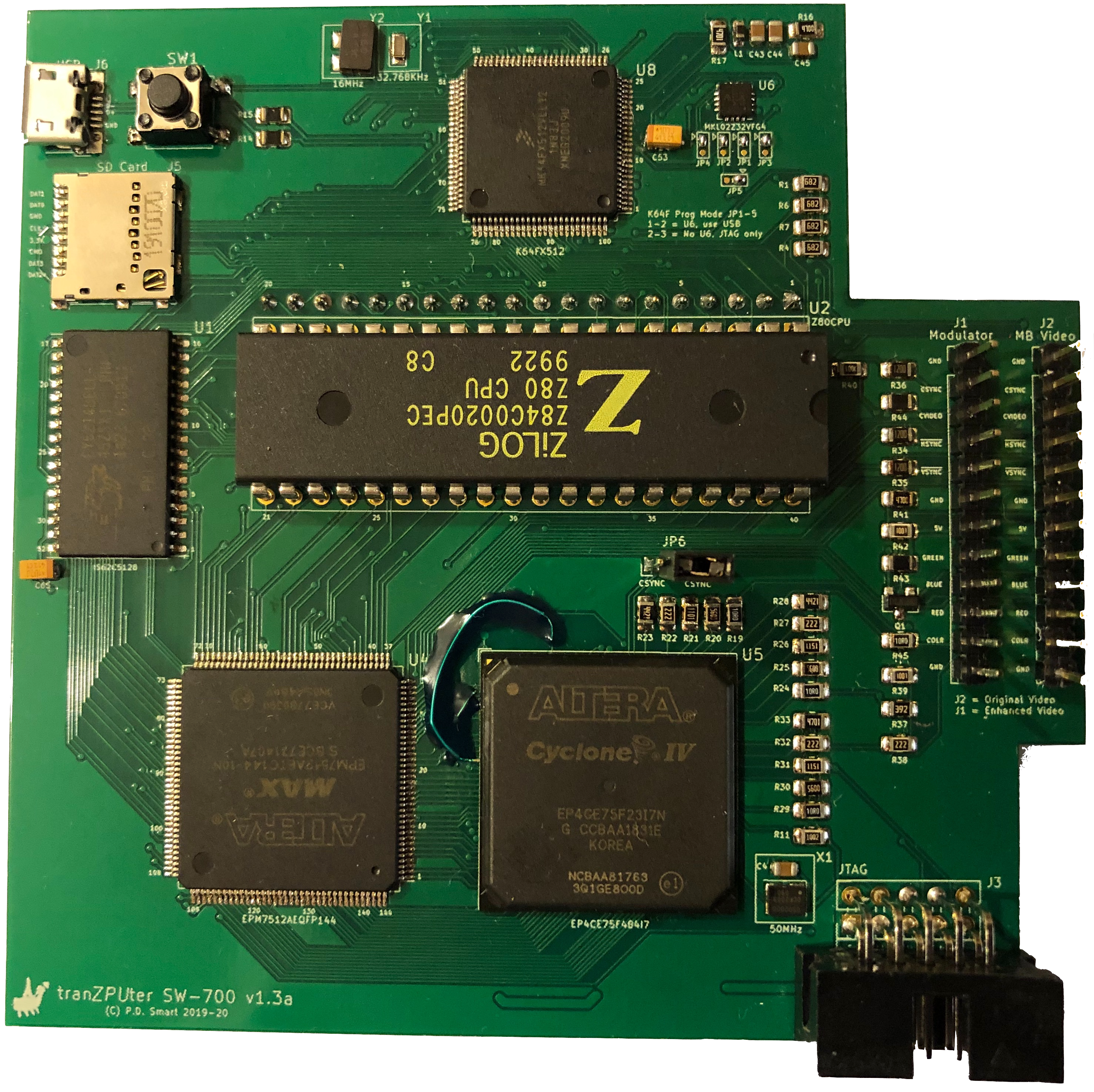
One of the primary requirements on the new version is to embed an I/O processor inside the Sharp MZ Series logic to handle configuration and User Interaction for tape/floppy load etc. To accommodate this, the tranZPUter SW-700 ARM Cortex-M4 processor will be used initially with design being tailored to allow the ZPU Evolution to slot in as an alternative, ie. for when the new version is migrated onto the MiSTer board.
The information below is based on version 1.0 and as the project advances will be updated with version 2.0 detail.
The I/O processor code and OSD is being developed snapshots of which can be seen below and the emulation hardware is running on the MZ-700 but more work is needed.
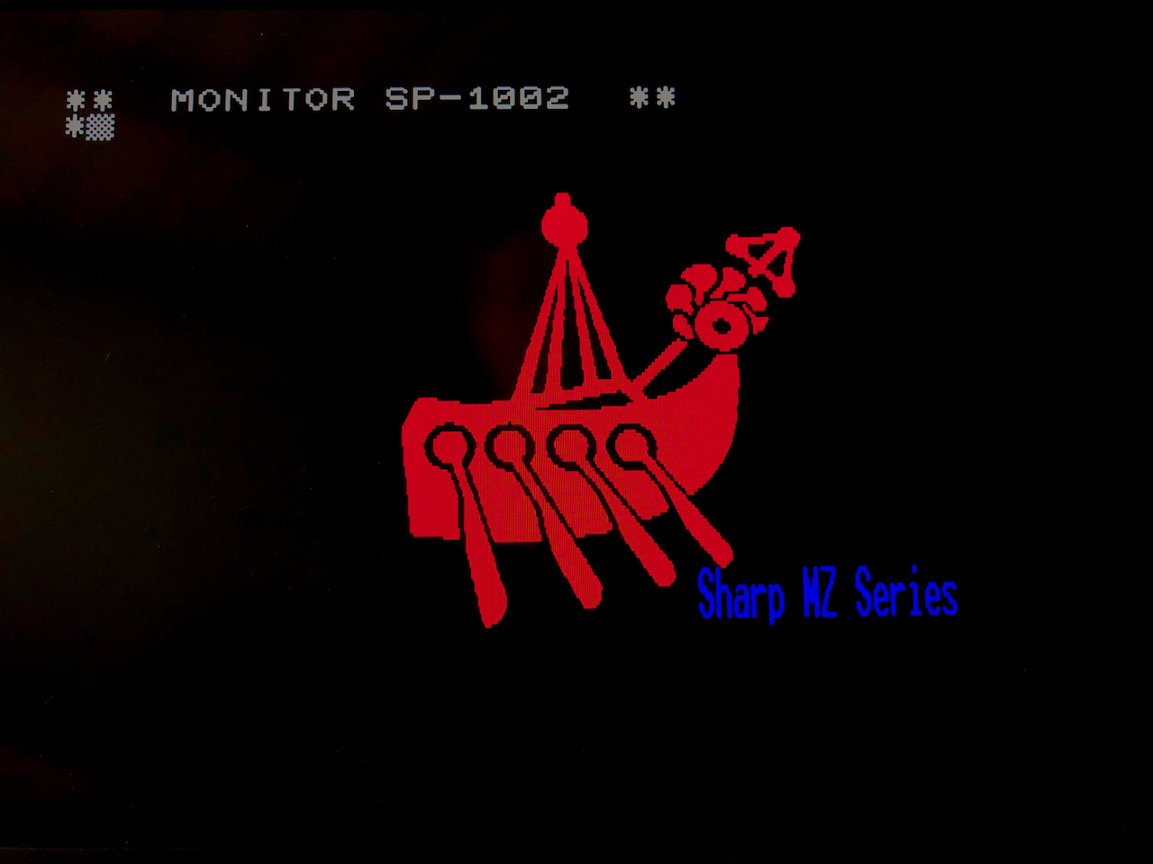 Emulation start, at the MZ-700 monitor prompt (tzfs), issuing the ‘mz’ command or an actual machine ie. ‘mz80a’ command will start the emulation configured as the reqested machine and the MZ-700 now behaves as though
it was the requested machine.
Emulation start, at the MZ-700 monitor prompt (tzfs), issuing the ‘mz’ command or an actual machine ie. ‘mz80a’ command will start the emulation configured as the reqested machine and the MZ-700 now behaves as though
it was the requested machine.
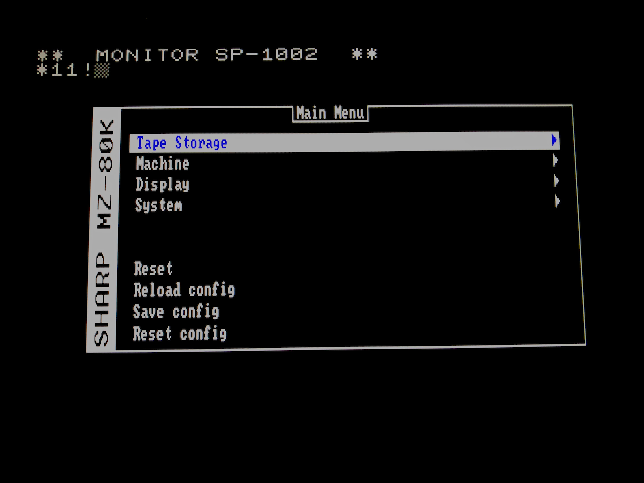 A familiar MiSTer like main menu. The presentation is a bit visually different but works in the same way as the MiSTer menus.
 As this is a real MZ-700 the emulation is runing on, you can choose the hardware tape drive or the FPGA emulated drive. When the hardware tape drive is chosen, all tape read and write
operations are performed to a physical cassette tape.
As this is a real MZ-700 the emulation is runing on, you can choose the hardware tape drive or the FPGA emulated drive. When the hardware tape drive is chosen, all tape read and write
operations are performed to a physical cassette tape.
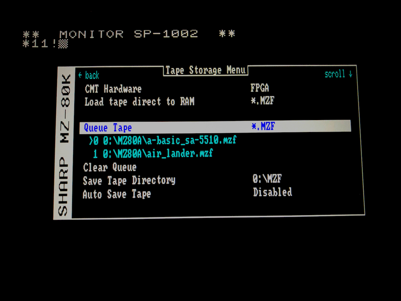
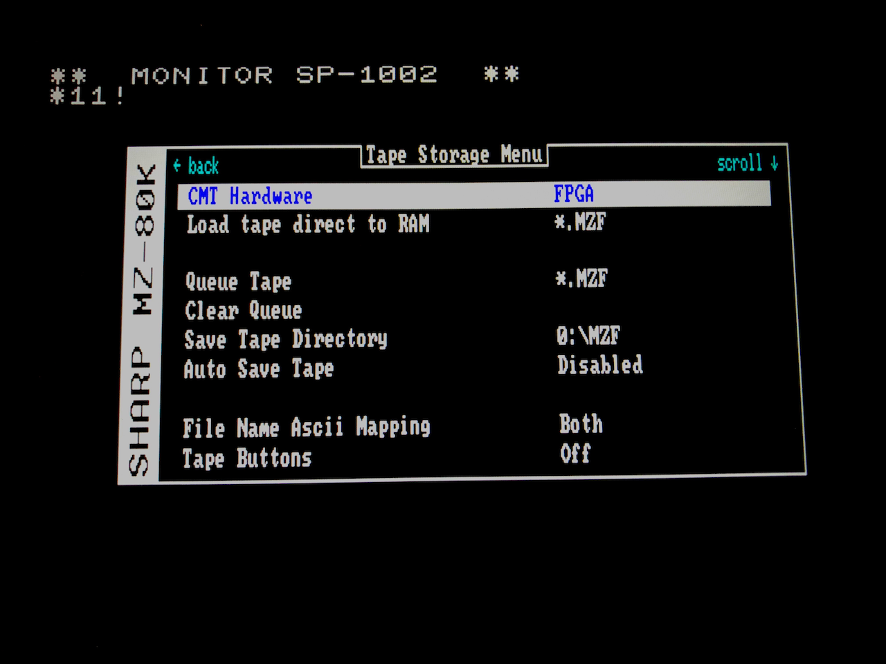 Switching to the FPGA emulated tape drive, you can now select, in a queue, the tape images to be presented to the emulator. The queue acts like a real cassette, as one tape image is processed
by the emulation the next is automatically uploaded. In this way games and databases which are multi-part function correctly. This mechanism is also very important for the more advanced
MZ-80B/MZ-2000 APSS tape drives where the computer can scan forward/backwards looking for a program and the queue rotates accordingly.
Switching to the FPGA emulated tape drive, you can now select, in a queue, the tape images to be presented to the emulator. The queue acts like a real cassette, as one tape image is processed
by the emulation the next is automatically uploaded. In this way games and databases which are multi-part function correctly. This mechanism is also very important for the more advanced
MZ-80B/MZ-2000 APSS tape drives where the computer can scan forward/backwards looking for a program and the queue rotates accordingly.
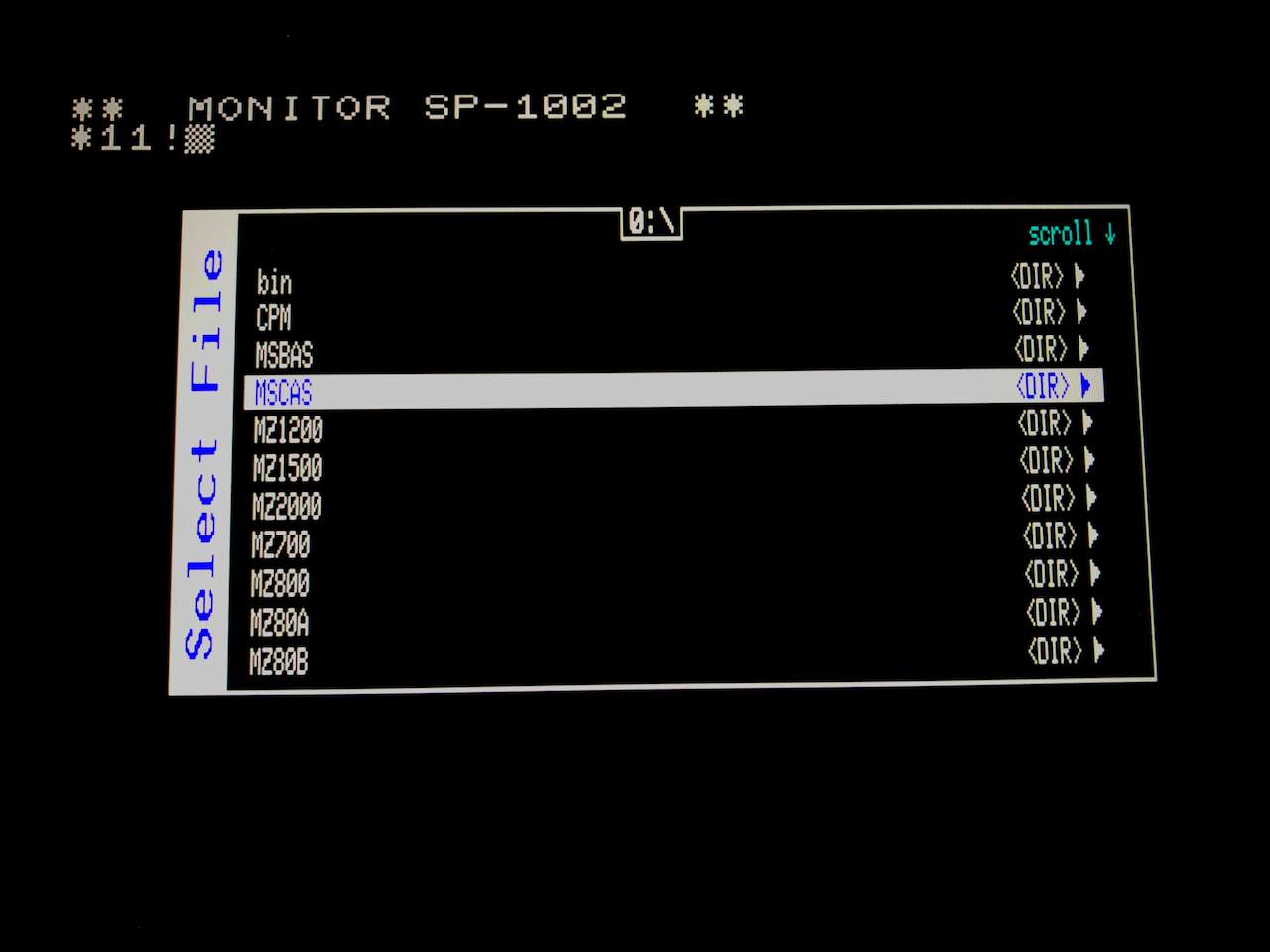 File selection is similar to the MiSTer but uses FAT32 naming conventions not Linux.
 Selected tape images are added to the queue. On 80K based machines, as the image is uploaded it is deleted from the queue. On 80B based machines the queue rotates according to the APSS
operations performed by the computer.
Selected tape images are added to the queue. On 80K based machines, as the image is uploaded it is deleted from the queue. On 80B based machines the queue rotates according to the APSS
operations performed by the computer.
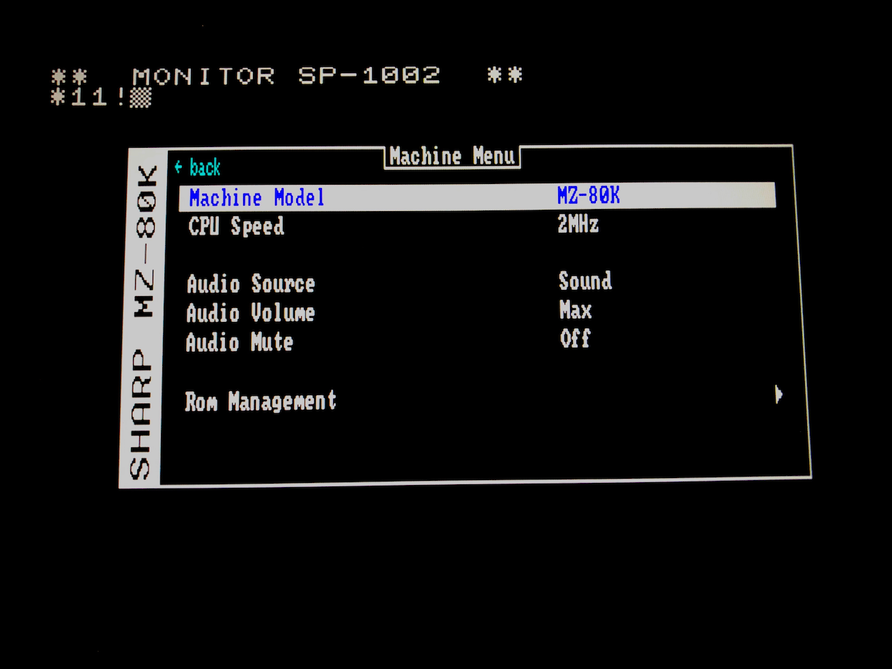 As per the MiSTer, you can choose which machine will be emulated along with configurable parameters.
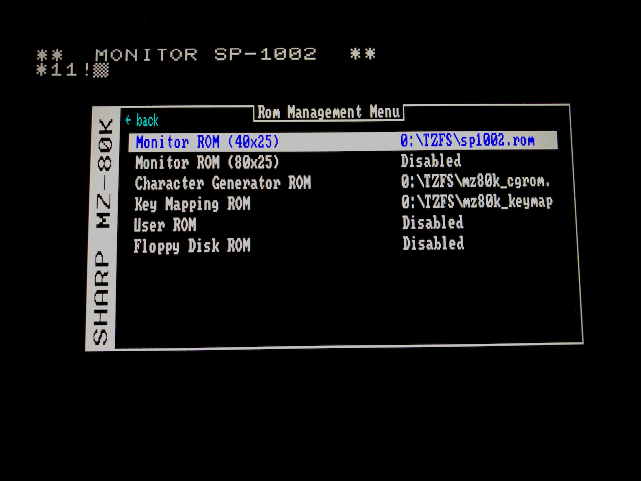 ROM images to be used in the emulation are configured here.
 The video module of the Sharp MZ Series has advanced since MiSTer v1.0 in it’s accuracy and capabilities. It acts as the video controller for the real MZ-700 in enhanced mode and as the video
controller for the Sharp MZ Series emulation. It is 32bit capable when driven by the ZPU and 8 bit when driven by the Sharp MZ Series.
The video module of the Sharp MZ Series has advanced since MiSTer v1.0 in it’s accuracy and capabilities. It acts as the video controller for the real MZ-700 in enhanced mode and as the video
controller for the Sharp MZ Series emulation. It is 32bit capable when driven by the ZPU and 8 bit when driven by the Sharp MZ Series.
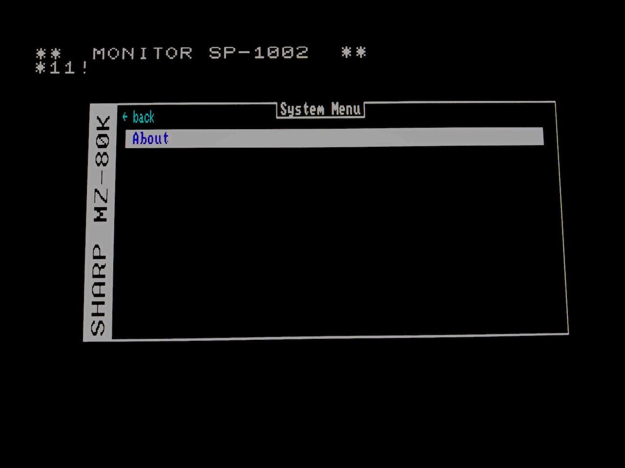 The system menu hasnt been completed yet apart from the About option.
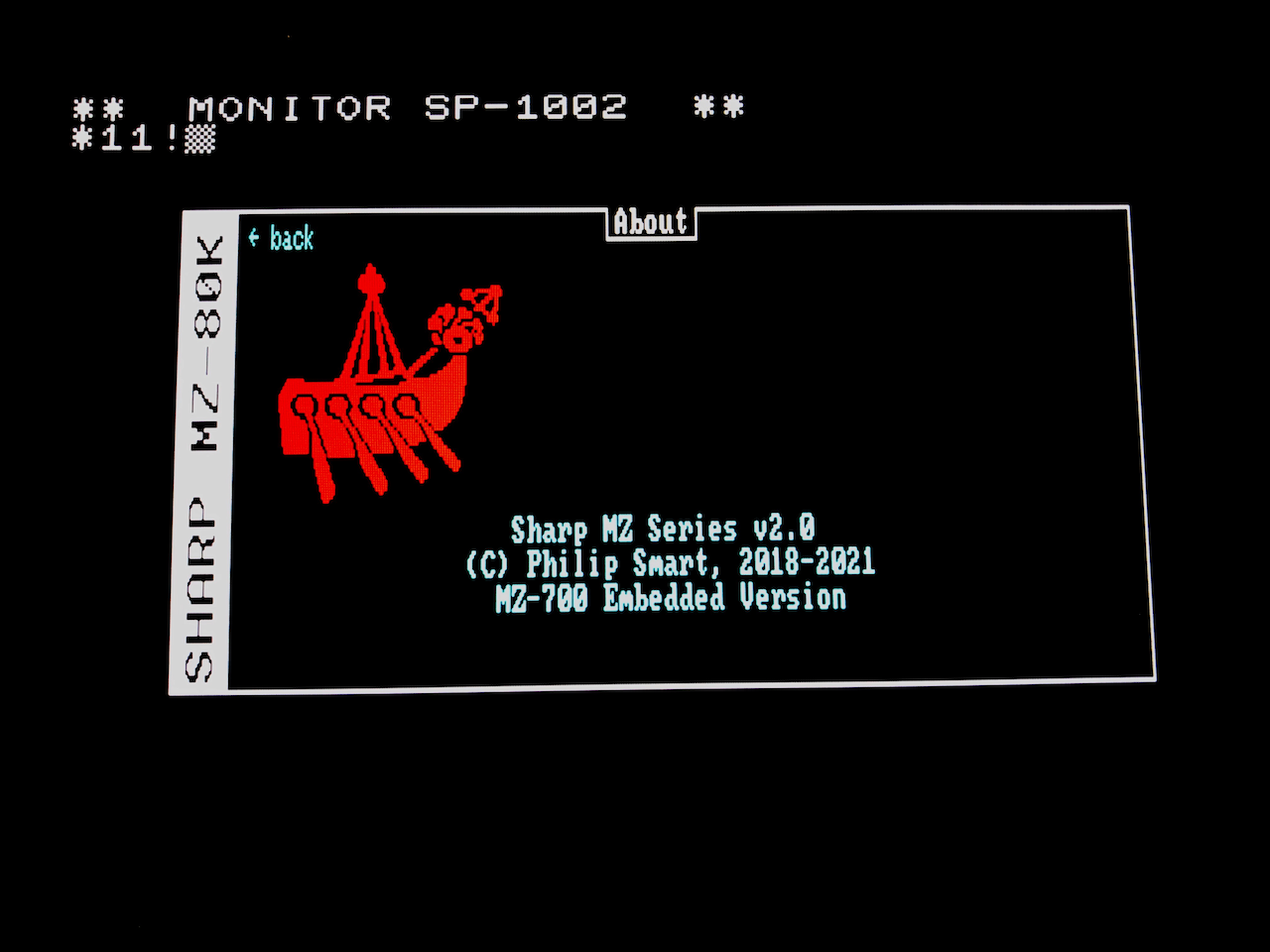 The about screen. This OSD has full 8 colour pixel graphics so could be used for many purposes other than an OSD.
The following emulations have been written:
| Emulator | Status | Emulator | Status | |
|---|---|---|---|---|
| MZ80K | Developed | MZ80C | Developed | |
| MZ1200 | Developed | MZ80A | Developed | |
| MZ700 | Developed | MZ80B | Developed | |
| MZ2000 | Partially Developed | MZ800 | Under development |
The current version of the emulator provides:
| 48K RAM for MZ80K,C,1200,A |
| 64K RAM for MZ700, MZ80B |
| Hardware Tape Read/Write with selectable 1x - 32x Fast Mode |
| APSS Tape Drive for the MZ80B/MZ2000 - Fully automated APSS using the Menu Queue system. |
| Turbo Mode 1x - 32x (ie. 112MHz for MZ700) |
| Programmable Character Generator (PCG-8000/PCG-1200) |
| 40x25, 80x25 Mono and Colour Display Modes |
| 320x200, 640x200 8 Colour Bit addressed Graphics |
| VGA Scaling |
| Updateable Monitor Rom, CGRom, Keymap, User Rom, FDC Rom per Emulation type. |
| i8253 mono audio or Tape audio |
Enhancements in test/under development
| Floppy Disk Drive/Controller 5.25” |
| Quick Disk Controller |
| Dual digital Joystick Input (MZ700) |
Known Issues
| Keyboard mappings could be better, especially for the MZ1200 which is the Japanese version of the MZ80A. |
| HDMI needs to be re-enabled in the design. |
| Need to complete the status frame buffer, used by the ZPU I/O processor for status information display - not critical to use. |
Design Summary
The idea of this design is to keep the emulation as independent of the HPS as possible (so it works standalone), only needing the HPS to set control registers, read/write tape/floppy cache ram with complete images and overlay the menu control system. The MiSTer/HPS system is an excellent base on which to host emulations, but there may be someone wanting to port this emulator to another target such as the Xilinx Zynq 7000 (which I have also been playing with). This in theory should allow easier porting if someone wants to port this emulator to another platform and control it with a PC (parallel port), HPS or instantiate another CPU as the menu control system.
As the Cyclone V SE on the Terasic DE10 has 5.5Mbits of memory, nearly all the RAM used by the emulation is on the FPGA. The Floppy Disk Controller may use HPS memory/external SDRAM depending on whether I decide to cache entire Floppy Disks as per the CMT unit or use the secondary SD card.
Installation
| 1. | Follow the Setup Guide to create a new SD boot disk. https://github.com/MiSTer-devel/Main_MiSTer/wiki/Setup-Guide |
| 2. | Copy across to the SD (via scp or mount the SD under Windows/Linux and use local copy commands) the latest RBF file from the releases folder, ie:- |
| scp SharpMZ_MiSTer/releases/SharpMZ_<date>.rbf root@<de10 ip address>/media/fat/SharpMZ.rbf | |
| Target name can be anything you like ending with .rbf. ‘root’ password is 1 on a default installation. The IP address can be obtained in the MiSTer Main System Menu before loading a core, press ESC to view. | |
| 3. | Make a SharpMZ directory on the SD card, ie: |
| ssh root@<de10 ip address> | |
| mkdir /media/fat/SharpMZ | |
| 4. | Copy any Rom Files, MZF Tape Files, DSK files across to the new directory, ie: |
| scp *.mzf root@<de10 ip address>:/media/fat/SharpMZ/ | |
| 5. | Start the MiSTer menu (ie. press the DE10 reset button if it is not showing). |
| 6. | Select the SharpMZ core (or whatever name you called it). |
| 7. | The emulator will boot into an MZ80A model with the SA-1510 monitor. |
| 8. | Press F12 to change the configuration, select Save Config to store it. |
Using the Emulator
Menu System
The MiSTer menu system is used extensively on this design as the Front End control. It allows for loading/saving of cassettes and floppy disks, setting the machine parameters, the display parameters, debugging and access to the MiSTer control menu.
Tape Storage
In order to use the emulation seriously, you need to be able to load and save existing programs. Initially (on the original machines) this was via a CMT (tape) unit and later moved on to Floppy/Quick Disks.
This menu controls the hardware CMT unit and has the following choices:
-
Load direct to RAM
This option allows you to load an MZF format tape file (ie. 128 bytes header + code) directly into RAM. It uses the Load Address and Size stored in the header in order to correctly locate the code and also stores the header in the Cassette Work area at 10F0H. After load is completed and warm reset is made, the details of the tape are displayed on-screen. In order to run the loaded program, simply issue the correct monitor command, ie. J1200 (Jump to 1200H where 1200H is shown as the Execution Address in the tape summary).
-
Queue Tape
A real cassette has 1 or more programs stored on it sequentially. The emulation cache only stores 1 full program so this is a mechanism to line up multiple programs and they will be fed into the emulation cache as it becomes empty, thus simulating a real cassette. Selecting this option presents you with a directory listing of all MZF files. Choose one per selection and it will be added to the Queue. The programs queued will be displayed on the menu.
For the MZ80B/MZ2000, the original tape drive was an automated APSS drive capable of searching backwards and forwards for a program. The queue emulates this by interpreting the APSS signals, moving the queue forward and backwards as necessary. Thus if you are to use a database program or similar which has multiple volumes you need to add these into the tape queue for the program to function correctly.
-
Clear Queue
This option allows you to purge all queue entries.
-
Save TapeThis option allows you to save a program to the MiSTer SD card which is in the emulation cache. Normally the emulation would have written a program/data to tape (ie. via the BASIC ‘SAVE’ command) which in reality is stored in the emulation cache. The tape is saved under the name given in the emulation save command (ie. in BASIC ‘SAVE “myfile”’ would result in a file called myfile.mzf being saved). -
Auto Save TapeThis option allows you to auto save the emulation cache. Ie. when an emulation save completes, a flag is raised which is seen by the MiSTer program and the emulation cache is saved to SD under the name given in the emulation. -
Tape Buttons
This option allows you to set the active Tape buttons, ie. Play, Record or Auto. Auto is a hardware mechanism to detect if the emulation is reading or writing to tape and process accordingly. Normally this is set to Auto but if you want to prevent tape read or write, change the setting as required.
-
Fast Tape Load
This option allows you to set the speed of the tape drive. On the original machines, the tape runs at 1200baud which is quite slow, so use of this option is recommended. You can select one of:
Off, 2x, 4x, 8x, 16x Selecting “Off” runs the tape drive at the original speed.
-
Map Header (Ascii)
This option allows you to set an on-the-fly conversion between Sharp ASCII and Ansi ASCII. Only Capital letters map 1:1 so if you save a file on the emulator using lower case letters, you will get a file saved on the SD card with what looks like garbage in the title. The same if you are reading a file in the emulator and you created it on the PC using standard ASCII, garbage will be seen inside the emulator. Using this option allows you to map the two character sets as required. You can select on of:
Off, Record, Play, Both Selecting “Off” performs no mapping, “Record” maps when saving an emulator file onto the SD card, “Play” maps when reading a file from the SD card into the emulator, “Both” maps during Record and Play.
NB: With the introduction of the APSS functionality, Save Tape and Auto Save Tape are redundant. When a program running on the emulation issues a save, the name is transferred through to the MiSTer Main binary which then uses that name to create a file on the SD card.
Machine
The emulation emulates several Sharp MZ computers and this menu allows you to choose the desired Sharp Model to be emulated.
-
Machine Model
This option allows you to choose which Sharp MZ computer is emulated. Currently the choices are:
MZ80K, MZ80C, MZ1200, MZ80A, MZ700, MZ80B, MZ2000, MZ800 in the pipeline -
CPU Speed
This option allows you to set the speed at which the emulation runs. Generally speaking, higher speeds can be beneficial in non-graphics based applications although some games benefit from a small speed boost. The choices are:
MZ80K/C/1200/A = 2MHz, 4MHz, 8MHz, 16MHz, 32MHz, 64MHz MZ700 = 3.5MHz, 7MHz, 14MHz, 28MHz, 56MHz, 112MHz MZ80B/2000 = 4MHz, 8MHz, 16MHz, 32MHz, 64MHz -
Audio Source
This option allows you to choose what is played through the audio output. The choices are:
Source Description Sound The mono audio generated by the emulation output on L/R channels. Tape The CMT signals as sound, Playback on Right channel, Record on Left channel. In theory you should be able to connect the right channel to an external tape drive and record to physical tape. -
Audio Volume
This option allows you to set the output volume. There are 16 possible steps from Min .. Max.
-
Audio Mute
This option allows you to Mute the audio output.
-
Rom Management
The emulation comes with the Monitor, Character Generator and Key Mapping Roms built-in for each machine emulated. This option selects a sub-menu which allows you to upload non-standard Roms when the emulation is started (ie. the Core is selected).
-
Machine Model
This option allows you to select the emulated Sharp MZ computer to which the custom rom images will affect. The choices are:
MZ80K, MZ80C, MZ1200, MZ80A, MZ700, MZ80B, MZ2000, MZ800 in the pipeline -
User ROM
On some machine models (ie. MZ80A) there exists a socket to place a User ROM, which will have control passed to it should the first byte be 0 and non-writeable. Although this option only exists on certain models, it is a nice to have feature it is available for all machine models. This option allows you to enable or disable the User ROM (NB. If you enable this option, it only enables hardware select, you still need to upload a ROM which has the first byte set to 0).
-
Floppy Disk ROM
A Floppy Disk drive was an expansion option for the Sharp MZ computers, and with the advent of the MZ700, a Quick Disk drive was also an option. These options typically held control software in a ROM at location F000H. This option allows you to enable this feature, albeit you still need to upload a ROM.
-
Enable Custom Rom This section allows you to enable custom Roms and select the image which will be uploaded. For each Rom, you can enable or disable. If enabled, you can choose the required file. The Roms which can be customized are:
Monitor (40x25) Monitor (80x25) Char Generator Key Mapping User Rom Floppy Disk The Monitor Rom is a special case. Most of the Personal Sharp MZ Computers were only able to display 40x25 characters so the Rom hardcodes these parameters. Some people required wider screens for use with CPM, so hardware modifications were made to create an 80x25 display. The emulation is capable of both modes but in order to run correctly, a different Monitor Rom for 80x25 display is needed.
-
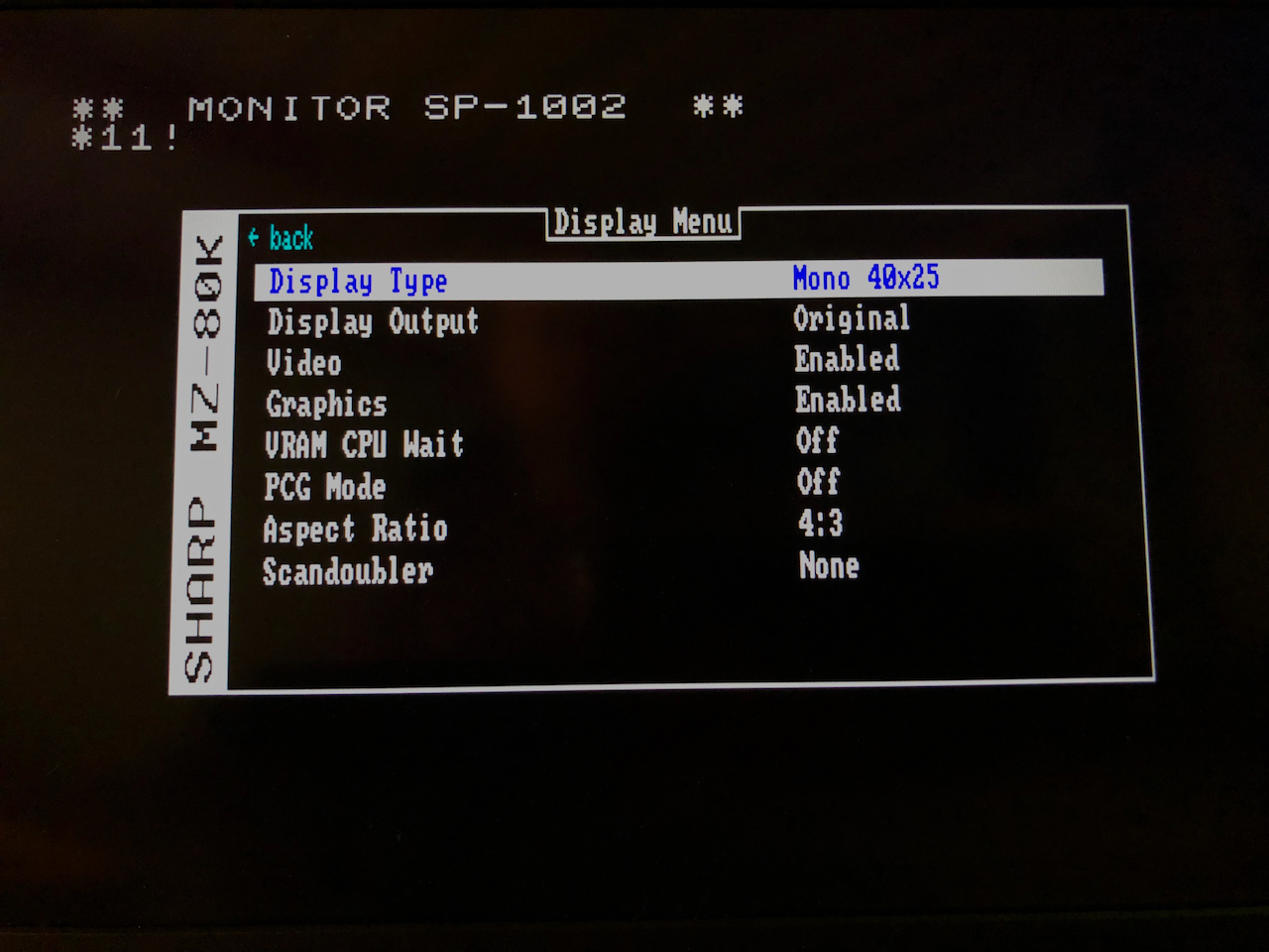
Display
The display on the Sharp MZ computers was originally quite simplistic. In order to cater for enhancements made in each model and by external vendors, the emulation has several configurable parameters which are grouped under this menu.
-
Display Type
This option allows you to select the display used. Normally, when a machine model is chosen, it defaults to the original display, this option allows you to override the default. The choices are:
Mono 40x25, Mono 80x25, Colour 40x25, Colour 80x25 -
VGA Scaling
In order to cater for various VGA monitors, this option programs the sync generator to mimic standard VGA signals. As VGA resolution is higher than the original Sharp MZ 40x25 screen (320x200 pixels), scaling occurs from the original format upto the VGA format.The choices are:
640x480@60Hz, Off Other formats are built into the hardware but not currently enabled as they are tied in with the status buffer, a pixel mapped area around the display for outputting information such as Record or Play or Floppy in-use light.
-
Video
An extension to the original design was the addition of a graphics frame buffer. It is possible to blend the original display video with the graphics frame buffer. This option allows you to Enable or Disable the original display video (ie. if you only want graphics).
-
Graphics
There were various add-on boards made available in order to display bit addressable pixel graphics. This is my extension to the original design and as I gather information on other add-on boards, I will adapt the hardware interface so it accommodates these options. Please see the section below on the graphics frame buffer details if needed. This option allows you to enable or disable the display of the graphics frame buffer (which is blended with the original character based video output).
-
Graphics Addr
As the emulation is catering for several Sharp MZ models in addition to adding graphics onto machines which originally didnt have graphics there can be a clash of I/O address for selecting the graphics mode and options. This option sets the default IO address for accessing the graphics control registers.
-
VRAM CPU Wait
I deviated from the original design by adding a pixel based display buffer. During the Vertical Blanking period, I expand the character based VRAM and Attribute RAM into pixels and store them in the display buffer (a double buffer technique). This consequently means that no snow/tearing will occur if the CPU accesses the VRAM/Attribute RAM during the visible display period. The original design added software waits (MZ80K) and hardware CPU wait states (MZ80A/700) to eliminate snow/tearing and due to the addition of double buffering, this is no longer needed. You can thus disable the wait states with this option and gain some speed or enable them to keep compatibility.
-
PCG Mode
All of the Sharp MZ computers used character generators which were hard coded in a ROM. External vendors offered add-ons to allow for a Programmable Character Generator based in RAM. This option enables the Programmable Character Generator which is compatible with the HAL PCG-8000/PCG-1200 add-ons. The options are:
ROM, RAM -
Aspect RatioThis option is a MiSTer framework extension which converts the Aspect Ratio from 4:3 to 16:9. It doesn’t work at the moment with VGA output but should work on HDMI. Use this option to choose the desired format. -
ScandoublerThis option is a MiSTer framework extension which doubles the scan lines to widen/improve the image of older computer displays. It doesn’t work correctly with VGA output at the moment but should work on HDMI. The choices are:"None", "HQ2x", "CRT 25%", "CRT 50%", "CRT 75%"
NB: Aspect Ratio and Scandoubler are currently disabled due to the inclusion of the VGA Scaling hardware. When HDMI output is compiled into the design in the near future they will be re-enabled.
Debugging
Debugging has now been made a compile time option. If debugging logic has been enabled in the RTL and Main MiSTer binary, the debugging options below will be available.
In FPGA’s, all the signals are internal and unless brought out to valuable IO pins, the signals are not easily evaluated on say a trusty Oscilloscope. Altera do have an on-chip solution in the form of it’s Signal Tap analyser which adds logic into your design to record signal states which are read to a PC realtime but this requires forethought in setting up the taps, the triggers, edges, compiling and hoping you have considered the correct points and have enough free memory and spare logic (generally you do). In saying this, there is something magic about seeing signals real-time and probing them with an oscilloscope and to this end i’ve added a debugging mode which can be used at any time without affecting the emulation (unless you choose a debug frequency in which case the emulation will run at the selected frequency).
Basically, the 8 LED’s on the main DE10 main board can display a selectable set of signals, either in auto mode (move from set to set after a fixed period) or a static set. The sample rate of the signals displayed on the LED’s is selectable from the Z80 CPU frequency down to 1Hz. You can also attach an oscilloscope onto the LED’s and thus see the waveform if a simple flicker is not sufficient. In addition, you can slow the CPU frequency down in steps from 1MHz to 1/10Hz so you have a good chance of seeing what is happening internally. This debugging addition is also a great method of understanding the internals of a computer and seeing the Z80 in action.
To use the debug mode, press F12 to enter the MiSTer menu, then select Debug and you are offered the following choices:
-
Select Memory Bank
This option allows you to select one of the memory banks so it can be written to a local (DE10 SD Card) file.
SysROM = System ROM. This is the complete concatenated set of Monitor ROM’s for all the emulations. SysRAM = System RAM. This is the 64K Main RAM. KeyMap = Key Mapping ROM. This is the complete concatenated set of Key Mapping’s for all the emulations. VRAM = Video RAM. This is the 2K Video RAM concatenated with the 2K Attribute RAM. CMTHDR = Cassette Header. This is the 128 byte memory holding the last loaded or saved tape header. CMTDATA = Cassette Data. This is the 64K memory holding the last loaded or saved tape data. CGROM = Character Generator ROM. This is the complete concatenated set of CGROM’s for all the emulations. CGRAM = Character Generator RAM. This is the 2K contents of the Programmable Character Generator RAM. All = This is the complete memory set as one file. -
Dump To <memory bank name>
Dump the selected memory bank. The system will show the file name used for the dump.
-
Debug Mode
Select to Enable or Disable
-
CPU Frequency
Select the CPU Frequency which can be one of:
CPU/CMT 1MHz 100KHz 10KHz 5KHz 1KHz 500Hz 100Hz 50Hz 10Hz 5Hz 2Hz 1Hz 0.5Hz 0.2Hz 0.1Hz -
Debug LEDS
Select to Enable or Disable
-
Sample Freq
This is the sampling frequency used to sample the displayed signals. It can be one of:
CPU/CMT 1MHz 100KHz 10KHz 5KHz 1KHz 500Hz 100Hz 50Hz 10Hz 5Hz 2Hz 1Hz 0.5Hz 0.2Hz 0.1Hz -
Signal Block
This is the signal block for display. It can be one of:
T80 = CPU Address/Data Bus and associated signals. I/O = Video, Keyboard and Select signals. IOCTL = External I/O Control. Address/Data and Select signals. Config = Register configuration signals. MZ80C I = 5 sets of signals relating to the MZ80K/C/1200/A/700/800. MZ80C II = An additional 5 sets of signals. MZ80B I = 5 sets of signals relating to the MZ80B/MZ2000. MZ80B II = An additional 5 sets of signals. -
Bank
This is the Bank within the Block to be displayed on the LED’s. It can be one of:
T80 = Auto, A7-0, A15-8, DI, Signals I/O = Auto, Video, PS2Key, Signals, IOCTL = Auto, A23-16, A15-8, A7-0m Signals Config = Auto, Config 1, Config 2, Config 3, Config 4, Config 5 MZ80C I = Auto, CS 1, CS 2, CS 3, INT/RE Clk MZ80C II = Auto, CMT 1, CMT 2, CMT 3, MZ80B I = Not yet defined. MZ80B II = Not yet defined.
System
This is the MiSTer main control menu which allows you to select a core, map keys, set bluetooth, view IP address etc.
Control Options
The menu system presents additional control options whose function is detailed below:
| Option | Description |
|---|---|
| Boot Reset | Perform an IPL reset on the Emulator when running in MZ80B/MZ2000 mode, ie. the boot switch you would press to bring up the IPL and load the initial program. |
| Reset | Reset the emulation, ie. toggle it’s reset line. |
| Reload config | Reload the configuration saved previously. Any change made in these menus can be stored for future use, if additional changes are unwanted, use this option to reload your last good configuration. |
| Save config | Save the configuration to SD card. Any changes you made in the Menu system will be saved. |
| Reset config | Reset the configuration to standard defaults. |
Graphics Frame Buffer
An addition to the original design is a 640x200/320x200 8 colour Graphics frame buffer. There were many additions to the Sharp MZ series to allow graphics (ie. MZ80B comes with standard mono graphics) display and as I don’t have detailed information of these 3rd party upgrades to date, I designed my own extension compatible with the standard Sharp MZ series video and graphics logic with the intention of adding hardware abstraction layers at a later date to add compatibility to support external vendor add-ons.
This frame buffer is made up of 3x16K RAM blocks, 1 per colour with a resolution of 640x200 which matches the output display buffer bit for bit. If the display is working at 40x25 characters then the resolution is 320x200, otherwise for 80x25 it is 640x200.
The RAM for the Graphics frame buffer can be switched into the main CPU address range C000H – FFFFH by programmable registers, 1 bank at a time (ie. Red, Green, Blue banks). This allows for direct CPU addressable pixels to be read and/or written. Each pixel is stored in groups of 8 (1 byte in RAM) scanning from right to left per byte, left to right per row, top to bottom. Ie. if the Red bank is mapped into CPU address space, the byte at C000H represents pixels 7 - 0 of 320/640 (X) at pixel 0 of 200 (Y). Thus 01H written to C000H would set Pixel 7 (X) on Row 0 (Y). This applies for Green and Blue banks when mapped into CPU address space.
In order to speed up the display, there is a Colour Write register, so that a write to the graphics RAM will update all 3 banks at the same time.
The programmable registers details are outlined below.
Switching Graphics RAM Banks into Z80 CPU Address Range
Graphics Bank Switch Set Register: I/O Address: E8H (232 decimal)
A read from this address switches in 1 of the 16Kb Graphics RAM pages (of the 3 pages) to C000 - FFFF. The bank which is switched in is set in the Control Register by bits 1/0 for Read operations and 3/2 for Write operations. This bank switch overrides all MZ80A/ MZ700 page switching functions.
Graphics Bank Switch Reset Register: I/O Address: E9H (233 decimal)
A read from this address switches out the Graphics RAM and returns to previous memory state.
Control Register (0xEA - 234 decimal)
| Bits | Description |
|---|---|
| 1:0 | Read mode (00=Red Bank, 01=Green Bank, 10=Blue Bank, 11=Not used). Select which bank to be read when enabled in CPU address space. |
| 3:2 | Write mode (00=Red Bank, 01=Green Bank, 10=Blue Bank, 11=Indirect). Select which bank to be written to when enabled in CPU address space. |
| 4 | VRAM Output. 0=Enable, 1=Disable. Output Character RAM to the display. |
| 5 | GRAM Output. 0=Enable, 1=Disable. Output Graphics RAM to the display. |
| 7:6 | Blend Operator (00=OR ,01=AND, 10=NAND, 11=XOR). Operator to blend Character display with Graphics Display. |
Colour Writer Registers (0xEB - 235 decimal to 0xED - 237 decimal )
| Bit | Pixel | I/O Addr | Colour | Description |
|---|---|---|---|---|
| 0 | 7 | 0xEBH | Red | Set to Red during indirect write. |
| 1 | 6 | 0xEBH | Red | |
| 2 | 5 | 0xEBH | Red | |
| 3 | 4 | 0xEBH | Red | |
| 4 | 3 | 0xEBH | Red | |
| 5 | 2 | 0xEBH | Red | |
| 6 | 1 | 0xEBH | Red | |
| 7 | 0 | 0xEBH | Red | Set to Red during indirect write. |
| 0 | 7 | 0xECH | Green | Set to Green during indirect write. |
| 1 | 6 | 0xECH | Green | |
| 2 | 5 | 0xECH | Green | |
| 3 | 4 | 0xECH | Green | |
| 4 | 3 | 0xECH | Green | |
| 5 | 2 | 0xECH | Green | |
| 6 | 1 | 0xECH | Green | |
| 7 | 0 | 0xECH | Green | Set to Green during indirect write. |
| 0 | 7 | 0xEDH | Blue | Set to Blue during indirect write. |
| 1 | 6 | 0xEDH | Blue | |
| 2 | 5 | 0xEDH | Blue | |
| 3 | 4 | 0xEDH | Blue | |
| 4 | 3 | 0xEDH | Blue | |
| 5 | 2 | 0xEDH | Blue | |
| 6 | 1 | 0xEDH | Blue | |
| 7 | 0 | 0xEDH | Blue | Set to Blue during indirect write. |
For Indirect mode (Control Register bits 3/2 set to 11), a write to the Graphics RAM when mapped into CPU address space C000H – FFFFH will see the byte masked by the Red Colour Writer Register and written to the Red Bank with the same operation for Green and Blue. This allows rapid setting of a colour across the 3 banks.
Status Frame Buffer
As part of the changes being made to the emulator with the intended onboarding of an I/O processor into the design, I have added an additional frame buffer which occupies the vertical lines outside of the normal screen rendering. ie. For a 640x480 VGA display, there are 80 rows available that can be seen on the screen but are outside the normal display (ie. 80x25 character display = 80x8 horizontal = 640 pixels, 2582 vertical = 400 pixels so 80 free), 40 above the main display and 40 below. This increases to 100 above and 100 below for 800x600 SVGA mode. The status frame buffer also overlays (programmable OR, XOR, AND & NAND bit blending) a block of video RAM on the main display to bring up a MiSTer style menu, the width and height varying according to the graphics mode selected. The menu is 256pixels hortizontal x 128pixels vertical.
The purpose of this status frame buffer is to allow the on board IO processor to have the ability to superimpose its own menu system without affecting the underlying emulator and to also display valued information, such as: Record, Play, QuickDisk, Floppy activity lights and status etc. This will then allow the emulator to be fully standalone and thus reducing the requirements from the MiSTer Main binary and increase its ability to run on various other FPGA development boards.
The status frame buffer control exists outside of the emulator domain and can only be accessed via the IOCTL mechanism used in the MiSTer design. This lends itself to be easily adapted to an IO processor.
Addresses of the status frame buffer:
| RAM | Address | Description |
|---|---|---|
| Status | 0x320000 | This is the RAM holding the pixels for the screen area above and below the emulator output, ie. 80col mode = 640x200, running in VGA timing this RAM holds the pixels for the top 40 and bottom 40 rows, each row being 640 pixels. |
| Menu | 0x322000 | This is the RAM holding the overlayed Menu which is 256x128 pixels. |
| Control | 0x324000 | Read the video parameter array to find all the timing values. This is a 32 x 32 array, bits 4:0 select the parameter, bits 9:5 select the mode entry. See example parameter table below. |
| Mode | 0x324400 | Read the current live video mode. |
For both the Status RAM and Menu RAM the memory width is 24 bits wide for 8 pixels in 8 colours.
| Bits | Colour | Information |
|---|---|---|
| 7:0 | Green | bit 7 is the left most visible pixel. |
| 15:8 | Red | bit 15 is the left most visible pixel. |
| 23:15 | Blue | bit 23 is the left most visible pixel. |
| Lowest memory address is the first starting pixel block, ie. 0x320000 bit 7+bit 15 + bit 23 = first status pixel. |
Example table of video parameters. The actual live values can be read from Control by the IO Processor (or MiSTer Main when no IO processor is embedded):
| Mode | Description | H_DSP_START | H_DSP_END | H_DSP_WND_START | H_DSP_WND_END | H_MNU_START | H_MNU_END | H_HDR_START | H_HDR_END | H_FTR_START | H_FTR_END | V_DSP_START | V_DSP_END | V_DSP_WND_START | V_DSP_WND_END | V_MNU_START | V_MNU_END | V_HDR_START | V_HDR_END | V_FTR_START | V_FTR_END | H_LINE_END | V_LINE_END | MAX_COLUMNS | H_SYNC_START | H_SYNC_END | V_SYNC_START | V_SYNC_END | H_PX | V_PX |
|---|---|---|---|---|---|---|---|---|---|---|---|---|---|---|---|---|---|---|---|---|---|---|---|---|---|---|---|---|---|---|
| 0 | MZ80B/2000 machines have a monochrome 60Hz display with scan of 512 x 260 for a 320x200 viewable area in 40Char mode. | 0 | 320 | 0 | 320 | 32 | 288 | 0 | 0 | 0 | 0 | 0 | 200 | 0 | 200 | 36 | 164 | 0 | 0 | 0 | 0 | 511 | 259 | 40 | 320 + 73 | 320 + 73 + 45 | 200 + 19 | 200 + 19 + 4 | 0 | 0) |
| 1 | MZ80B/2000 machines have a monochrome 60Hz display with scan of 1024 x 260 for a 640x200 viewable area in 80Char mode. | 0 | 640 | 0 | 640 | 192 | 448 | 0 | 0 | 0 | 0 | 0 | 200 | 0 | 200 | 36 | 164 | 0 | 0 | 0 | 0 | 1023 | 259 | 80 | 640 + 146 | 640 + 146 + 90 | 200 + 19 | 200 + 19 + 4 | 0 | 0) |
| 2 | MZ80K/C/1200/A machines have a monochrome 60Hz display with scan of 512 x 260 for a 320x200 viewable area. | 0 | 320 | 0 | 320 | 32 | 288 | 0 | 0 | 0 | 0 | 0 | 200 | 0 | 200 | 36 | 164 | 0 | 0 | 0 | 0 | 511 | 259 | 40 | 320 + 73 | 320 + 73 + 45 | 200 + 19 | 200 + 19 + 4 | 0 | 0) |
| 3 | MZ80K/C/1200/A machines with an adapted monochrome 60Hz display with scan of 1024 x 260 for a 640x200 viewable area. | 0 | 640 | 0 | 640 | 192 | 448 | 0 | 0 | 0 | 0 | 0 | 200 | 0 | 200 | 36 | 164 | 0 | 0 | 0 | 0 | 1023 | 259 | 80 | 640 + 146 | 640 + 146 + 90 | 200 + 19 | 200 + 19 + 4 | 0 | 0) |
| 4 | MZ700 has a colour 50Hz display with scan of 568 x 320 for a 320x200 viewable area. | 0 | 320 | 0 | 320 | 32 | 288 | 0 | 0 | 0 | 0 | 0 | 200 | 0 | 200 | 36 | 164 | 0 | 0 | 0 | 0 | 567 | 311 | 40 | 320 + 80 | 320 + 80 + 40 | 200 + 45 | 200 + 45 + 3 | 0 | 0) |
| 5 | MZ700 has colour 50Hz display with scan of 1136 x 320 for a 640x200 viewable area. | 0 | 640 | 0 | 640 | 192 | 448 | 0 | 0 | 0 | 0 | 0 | 200 | 0 | 200 | 36 | 164 | 0 | 0 | 0 | 0 | 1134 | 311 | 80 | 640 + 160 | 640 + 160 + 80 | 200 + 45 | 200 + 45 + 3 | 0 | 0) |
| 6 | MZ80K/C/1200/A machines with MZ700 style colour @ 60Hz display with scan of 512 x 260 for a 320x200 viewable area. | 0 | 320 | 0 | 320 | 32 | 288 | 0 | 0 | 0 | 0 | 0 | 200 | 0 | 200 | 36 | 164 | 0 | 0 | 0 | 0 | 511 | 259 | 40 | 320 + 73 | 320 + 73 + 45 | 200 + 19 | 200 + 19 + 4 | 0 | 0) |
| 7 | MZ80K/C/1200/A machines with MZ700 style colour @ 60Hz display with scan of 1024 x 260 for a 640x200 viewable area. | 0 | 640 | 0 | 640 | 192 | 448 | 0 | 0 | 0 | 0 | 0 | 200 | 0 | 200 | 36 | 164 | 0 | 0 | 0 | 0 | 1023 | 259 | 80 | 640 + 146 | 640 + 146 + 90 | 200 + 19 | 200 + 19 + 4 | 0 | 0) |
| 8 | 640x480 @ 60Hz timings for 40Char mode monochrome. | 0 | 640 | 0 | 640 | 192 | 448 | 0 | 640 | 0 | 640 | 0 | 480 | 39 | 439 | 111 | 367 | 8 | 24 | 444 | 479 | 831 | 519 | 40 | 640 + 16 | 640 + 16 + 96 | 480 + 10 | 480 + 10 + 2 | 1 | 1) |
| 9 | 640x480 @ 60Hz timings for 40Char mode monochrome. | 0 | 640 | 0 | 640 | 192 | 448 | 0 | 640 | 0 | 640 | 0 | 480 | 39 | 439 | 111 | 367 | 8 | 24 | 444 | 479 | 799 | 524 | 40 | 640 + 16 | 640 + 16 + 96 | 480 + 10 | 480 + 10 + 2 | 1 | 1) |
| 10 | 640x480 @ 60Hz timings for 80Char mode monochrome. | 0 | 640 | 0 | 640 | 192 | 448 | 0 | 640 | 0 | 640 | 0 | 480 | 39 | 439 | 111 | 367 | 8 | 24 | 444 | 479 | 831 | 508 | 80 | 640 + 16 | 640 + 16 + 96 | 480 + 10 | 480 + 10 + 2 | 0 | 1) |
| 11 | 640x480 @ 60Hz timings for 80Char mode monochrome. | 0 | 640 | 0 | 640 | 192 | 448 | 0 | 640 | 0 | 640 | 0 | 480 | 39 | 439 | 111 | 367 | 8 | 24 | 444 | 479 | 799 | 524 | 80 | 640 + 16 | 640 + 16 + 96 | 480 + 10 | 480 + 10 + 2 | 0 | 1) |
| 12 | 640x480 @ 60Hz timings for 80Char mode colour. | 0 | 640 | 0 | 640 | 192 | 448 | 0 | 640 | 0 | 640 | 0 | 480 | 39 | 439 | 111 | 367 | 8 | 24 | 444 | 479 | 831 | 508 | 40 | 640 + 16 | 640 + 16 + 96 | 480 + 10 | 480 + 10 + 2 | 1 | 1) |
| 13 | 640x480 @ 60Hz timings for 40Char mode colour. | 0 | 640 | 0 | 640 | 192 | 448 | 0 | 640 | 0 | 640 | 0 | 480 | 39 | 439 | 111 | 367 | 8 | 24 | 444 | 479 | 799 | 524 | 40 | 640 + 16 | 640 + 16 + 96 | 480 + 10 | 480 + 10 + 2 | 1 | 1) |
| 14 | 640x480 @ 60Hz timings for 80Char mode colour. | 0 | 640 | 0 | 640 | 192 | 448 | 0 | 640 | 0 | 640 | 0 | 480 | 39 | 439 | 111 | 367 | 8 | 24 | 444 | 479 | 831 | 508 | 80 | 640 + 16 | 640 + 16 + 96 | 480 + 10 | 480 + 10 + 2 | 0 | 1) |
| 15 | 640x480 @ 60Hz timings for 80Char mode colour. | 0 | 640 | 0 | 640 | 192 | 448 | 0 | 640 | 0 | 640 | 0 | 480 | 39 | 439 | 111 | 367 | 8 | 24 | 444 | 479 | 799 | 524 | 80 | 640 + 16 | 640 + 16 + 96 | 480 + 10 | 480 + 10 + 2 | 0 | 1) |
| 16 | 640x480 @ 72Hz timings for 40Char mode monochrome. | 0 | 640 | 0 | 640 | 192 | 448 | 0 | 640 | 0 | 640 | 0 | 480 | 39 | 439 | 111 | 367 | 8 | 24 | 444 | 479 | 831 | 519 | 40 | 640 + 24 | 640 + 24 + 40 | 480 + 9 | 480 + 9 + 2 | 1 | 1) |
| 17 | 640x480 @ 72Hz timings for 80Char mode monochrome. | 0 | 640 | 0 | 640 | 192 | 448 | 0 | 640 | 0 | 640 | 0 | 480 | 39 | 439 | 111 | 367 | 8 | 24 | 444 | 479 | 831 | 519 | 80 | 640 + 24 | 640 + 24 + 40 | 480 + 9 | 480 + 9 + 2 | 0 | 1) |
| 18 | 640x480 @ 72Hz timings for 40Char mode colour. | 0 | 640 | 0 | 640 | 192 | 448 | 0 | 640 | 0 | 640 | 0 | 480 | 39 | 439 | 111 | 367 | 8 | 24 | 444 | 479 | 831 | 519 | 40 | 640 + 24 | 640 + 24 + 40 | 480 + 9 | 480 + 9 + 2 | 1 | 1) |
| 19 | 640x480 @ 72Hz timings for 80Char mode colour. | 0 | 640 | 0 | 640 | 192 | 448 | 0 | 640 | 0 | 640 | 0 | 480 | 39 | 439 | 111 | 367 | 8 | 24 | 444 | 479 | 831 | 519 | 80 | 640 + 24 | 640 + 24 + 40 | 480 + 9 | 480 + 9 + 2 | 0 | 1 |
Links
The Sharp MZ Series Computers were not as wide spread as Commodore, Atari or Sinclair but they had a dedicated following. Given their open design it was very easy to modify and extend applications such as the BASIC interpreters and likewise easy to add hardware extension. As such, a look round the web finds some very comprehensive User Groups with invaluable resources. If you need manuals, programs, information then please look (for starters) at the following sites:
| Site | Description |
|---|---|
| Engineers At Work | My personal projects site. |
| SharpMZ.org | Original SharpMZ site, excellent resource but the owner has retired now. |
| SharpMZ.no | Site to replace the Original SharpMZ site, still under development. |
| mz-80a.com | MZ-80A Sectors guide to the Sharp MZ-80A |
| Sharp Users Club | Still active, the Sharp Users Club. |
| SharpMZ Forum | Active Sharp MZ forum for all models. |
| SCAV | Czech site for Sharp information and downloads, use chrome to auto translate Czech |
Credits
My original intention was to port the MZ80C Emulator written by Nibbles Lab https://github.com/NibblesLab/mz80c_de0 to the Terasic DE10 Nano. After spending some time analyzing it and trying to remove the NIOSII dependency, I discovered the MISTer project, at that point I decided upon writing my own emulation. Consequently some ideas in this code will have originated from Nibbles Lab and the i8253/Keymatrix modules were adapted to work in this implementation. Thus due credit to Nibbles Lab and his excellent work. Also credit to Sorgelig for his hard work in creating the MiSTer framework and design of some excellent hardware add-ons. The MiSTer framework makes it significantly easier to design/port emulations. Where I have used or based any component on a 3rd parties design I have included the original authors copyright notice within the headers or given due credit. All 3rd party software, to my knowledge and research, is open source and freely useable, if there is found to be any component with licensing restrictions, it will be removed from this repository and a suitable link/config provided.
Licenses
This design, hardware and software, is licensed under the GNU Public Licence v3.
The Gnu Public License v3
The source and binary files in this project marked as GPL v3 are free software: you can redistribute it and-or modify it under the terms of the GNU General Public License as published by the Free Software Foundation, either version 3 of the License, or (at your option) any later version.
The source files are distributed in the hope that it will be useful, but WITHOUT ANY WARRANTY; without even the implied warranty of MERCHANTABILITY or FITNESS FOR A PARTICULAR PURPOSE. See the GNU General Public License for more details.
You should have received a copy of the GNU General Public License along with this program. If not, see http://www.gnu.org/licenses/.