 MZ-2500/2800 Keyboard Interface
Overview
A major issue with later vintage Sharp computers is keyboards. For whatever reason, either lost, in storage or bought by collectors, a large majority of MZ-2500/2800/3500/X1/X68000 machines are now sold without keyboard. Apart from the X68000 where you can still 'kind of' use it with a joystick, the machine is just a paper weight without one. Sellers know this and those that come up for sale can be GBP100-200 or more.
Some resourceful Japanese guys (classicpc.org, or Youkan) and Martin at 8bity.cz have developed interfaces to convert common PS/2 or USB PC keyboards so that they
work with these keyboardless Sharp machines. On the whole, for the X1 and X68000 these interfaces work perfectly and are wrapped up in a professional small form factor case. The MZ-2500 interface though has some issues, not least the
available design is based on an ST Development board and the firmware is closed source. It was made into a professional adapter for sale in Akihabara but seems no longer available. For me the development version of the MZ-2500 interface on the web, at
least the version I made up, is temperamental and doesnt work with the MZ-2800 (as confirmed by some Japanese contacts). As I need a working reliable unit so that I can complete my MZ-2500/MZ-2800 machines I have under renovation (all without keyboards) I had to consider other options.
Im currently renovating 2x MZ-2500 machines, one of which I will be keeping and also an MZ-2800. Given the limitations of Youkan’s development board based interface, I decided on designing my own using the physical format used by Martin at 8bity.cz,
namely a KM24 small form factor cased device. Initially looking at the Renesas R8C processor used by Sato Kyouchi for his very reliable X1 interface, I hoped to build on the
design adding supporting hardware and make a 2 in 1 device, PS/2 -> X1/MZ-2500/2800. The R8C is a lovely small MCU, easy to work with and program but it suffered from performance issues for this requrement, even at 20MHz it would take
1uS to respond to an interrupt, which is fine for most applications, including PS/2 and X1 keyboard protocol’s, but for the MZ-2500 is was too slow.
In order to understand the requirements of interfacing to an MZ-2500/MZ-2800 the following section describe the hardware and it's protocol in more detail.
MZ-2500 Keyboard Protocol
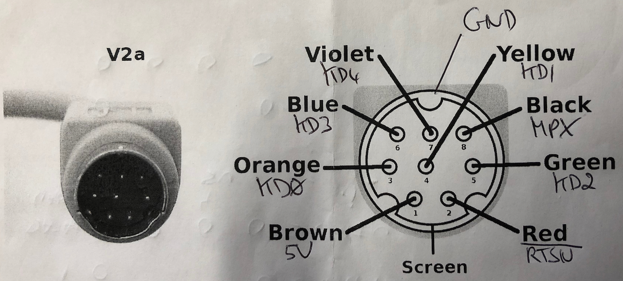
The hardware interface comprises of 7 signals, 5V and GND using a shielded 8pin mini-din socket and plug, with plug wiring below.
| Signal | Direction | Logic State | Description |
|---|---|---|---|
| RTSN Row Strobe |
Main Unit -> Keyboard | HIGH (‘1’) | A Row address is being transmitted from the main unit to the keyboard. |
| LOW (‘0’) | The keyboard is transmitting requested data over the 4 bit bidirectional bus KD[3:0]. | ||
| KD4 Type Strobe |
Main Unit -> Keyboard | HIGH (‘1’) | The keyboard must return the actual key matrix data as referenced by the Row number. |
| LOW (‘0’) | The keyboard must return a logical AND of all the keys, ie. D0 = AND of bit 0 on ROWS 0 to 13, D1 = AND of bit 1 on ROWS 0 to 13 etc. | ||
| MPX Nibble MUX Strobe |
Main Unit -> Keyboard | HIGH (‘1’) | The upper nibble of the requested ROW (or AND of row data as directed by KD4) is sent from the keyboard to the main unit. |
| LOW (‘0’) | The lower nibble of the requested ROW (or AND of row data as directed by KD4) is sent from the keyboard to the main unit. | ||
| KD[3:0] Bi-dir bus |
Main Unit -> Keyboard | Active when RTSN = HIGH (‘1’), transmits the 4 bit row number of the row data from the keyboard matrix. | |
| Keyboard -> Main Unit | Active when RTSN = LOW (‘0’), transmits 4 bits of the 8 bit column data of the requested row. 4 bits is selected by KD4 & MPX. |
There are two main modes of operation, a test all (STROBEALL) keys mode, used whilst waiting for a key to be pressed which is followed on by a manual scan of all rows to retrieve column data to locate the pressed key.
For key data retrieval the protocol is as follows:
- RTSN goes active HIGH and remains active for 1.08us. The initial RTSN period, after detection of a key via STROBEALL, is 1.08us active HIGH and 660ns inactive LOW. Thereafter the period is a uniform 660ns active HIGH and 680ns inactive LOW.
- The mainboard sends a scan row to the keyboard which becomes valid 160ns after the rising edge of RTSN.
- The scan row is read by the keyboard in the remaining 920ns from KD[3:0]. KD4 state (or state change) precedes the rising edge of RTSN, generally changes on the falling edge prior to the triggering active edge of RTSN.
- KD4 is sampled, when LOW the logical AND of all keys per column is set for retrieval, when HIGH the actual column of the selected row is set for retrieval.
- On the RTSN falling edge (RTSN goes inactive LOW), MPX goes HIGH for 320ns and the upper nibble of the data set for retrieval is output by the keyboard on KD[3:0] after 20ns from the MPX rising edge. The data is then read by the mainboard within the remaining 300ns before MPX goes LOW.. When MPX goes LOW ‘) the lower nibble of the data set for retrieval is output on KD[3:0] with the same 320ns timing interval. After 320ns RTSN will then rise again.
- The above repeats whilst a key is being pressed, the row sent can vary or remain static, for example if reading the same key to determine bounce or repeat.
- If no key is being pressed, switch to STROBEALL mode.
For the STROBEALL mode, the protocol is as follows:
- During the STROBEALL mode, KD4 is held LOW and apart from a 20ns glitch which varies from 18.996ms to 198.83ms it doesnt change state. The glitch looks like a hardware oversight.
- During STROBEALL mode, RTSN has an even period, 660ns active HIGH, 660ns active LOW. When RTSN goes HIGH, the hardware switches for the mainboard to send a ROW to the keyboard as in the protocol above. The row is ignored (or appears to be ignored as it repeats ad-infinitum with a constant value of 4 which is not a meaningful row).
- KD4 is sampled, when LOW the logical AND of all keys per column is set for retrieval, when HIGH the actual column of the selected row is set for retrieval.
- On the RTSN falling edge (RTSN goes inactive LOW), MPX goes HIGH for 320ns and the upper nibble of the data set for retrieval is output by the keyboard on KD[3:0], which is valid 20ns after the MPX rising edge. The data is then read by the mainboard within the remaining 300ns before MPX goes LOW. When MPX goes LOW the lower nibble of the data set for retrieval is output on KD[3:0] with the same 320ns timing interval. After 320ns RTSN will then rise again.
- If a key is being pressed, switch to key data retrieval mode else repeat the above in a loop.
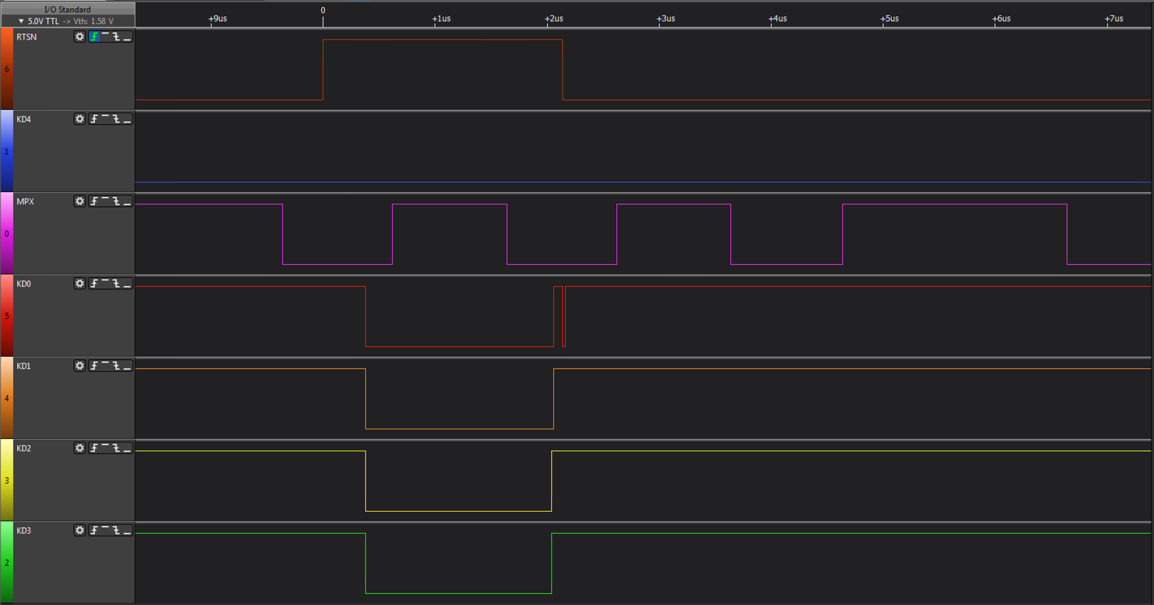
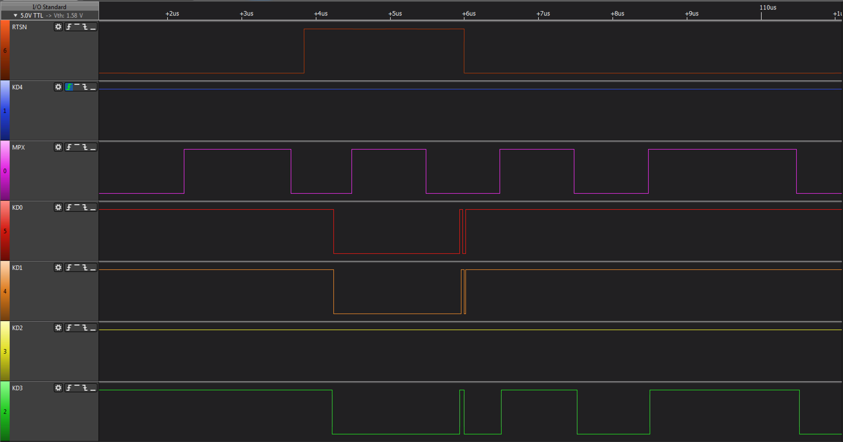
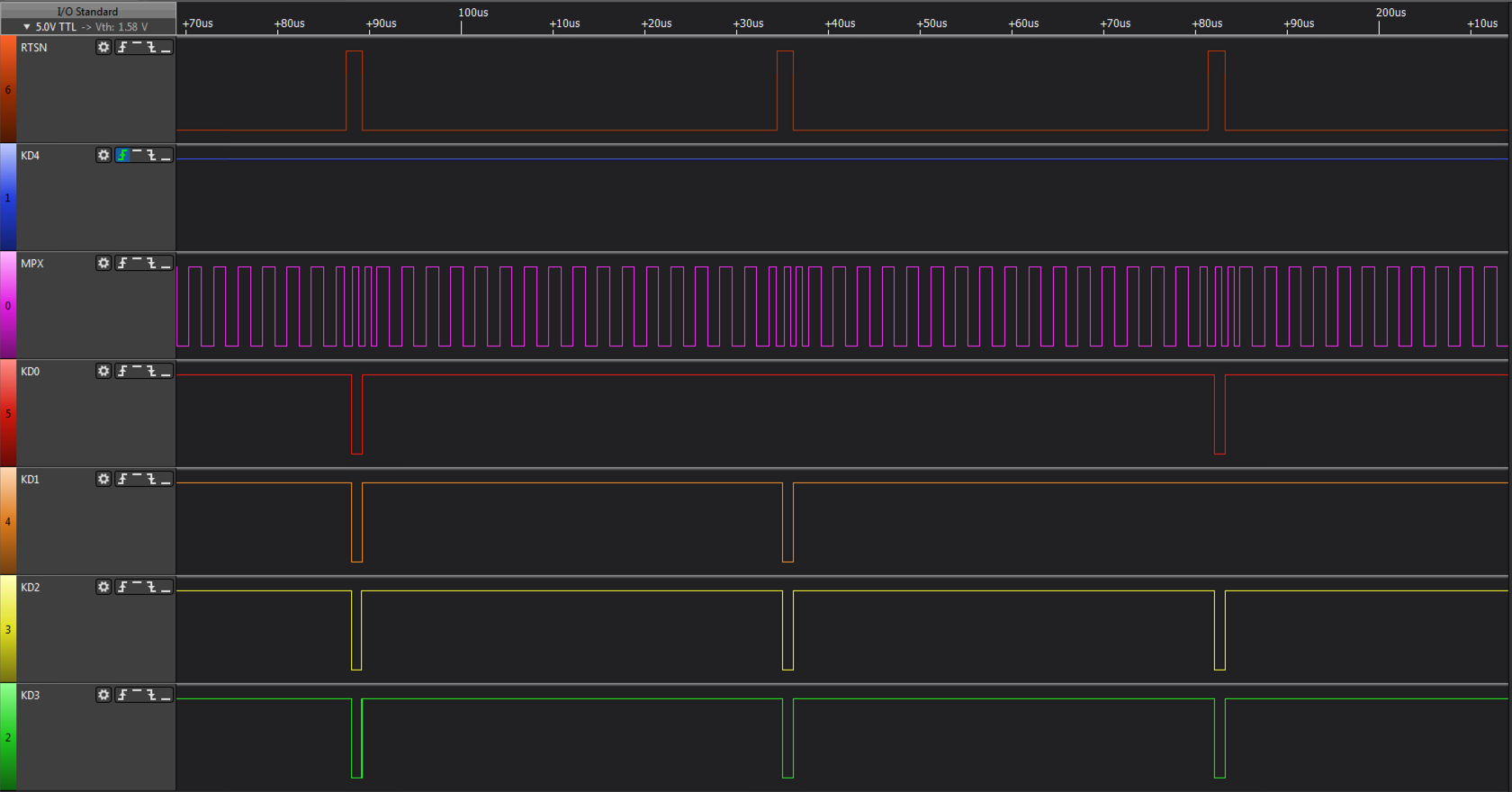
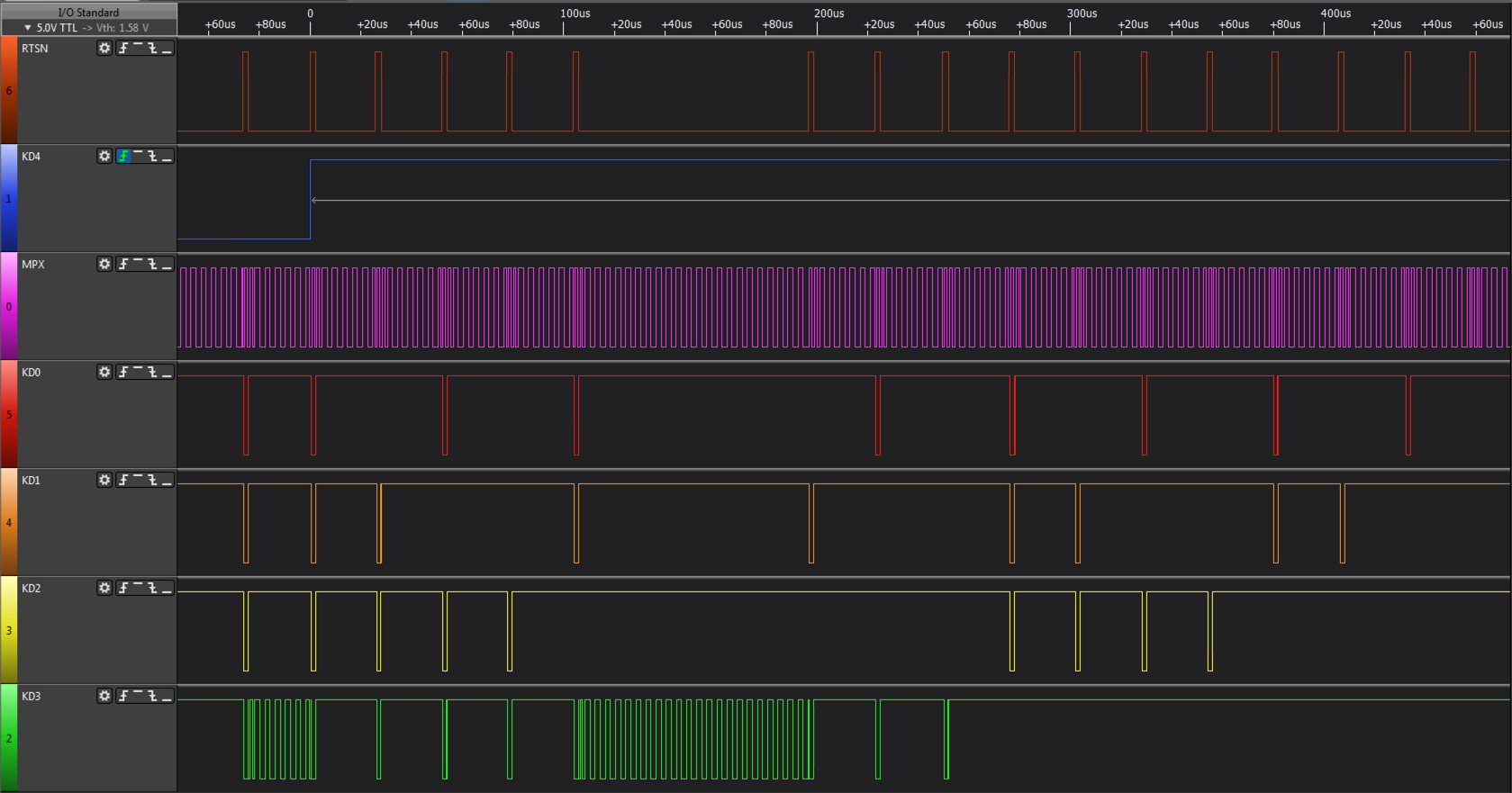
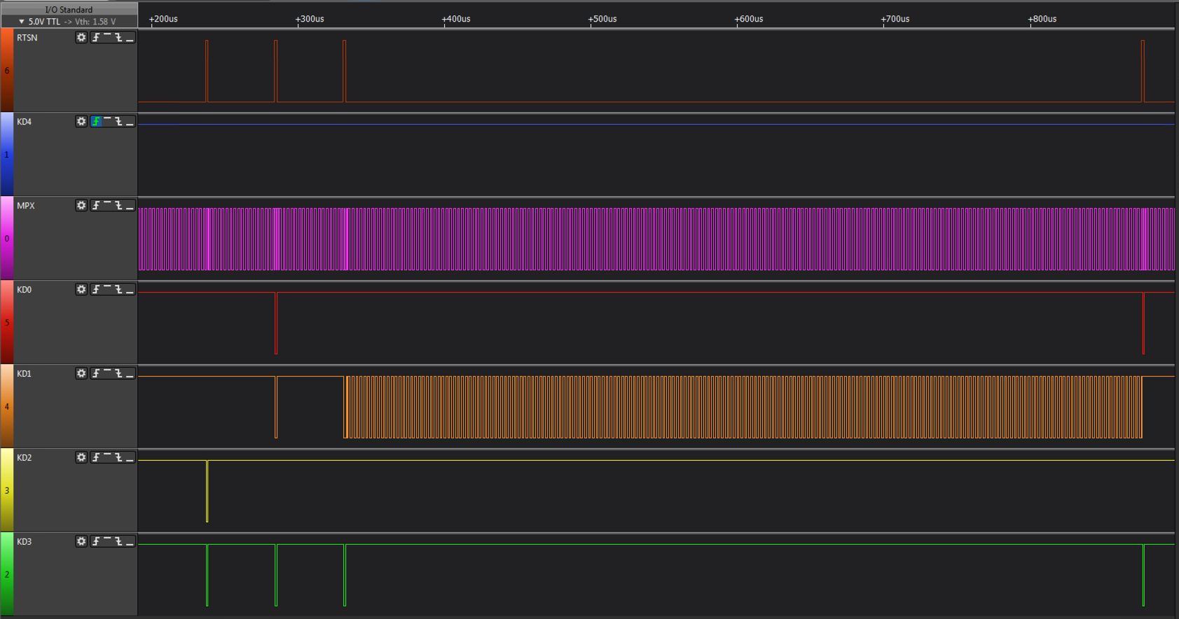
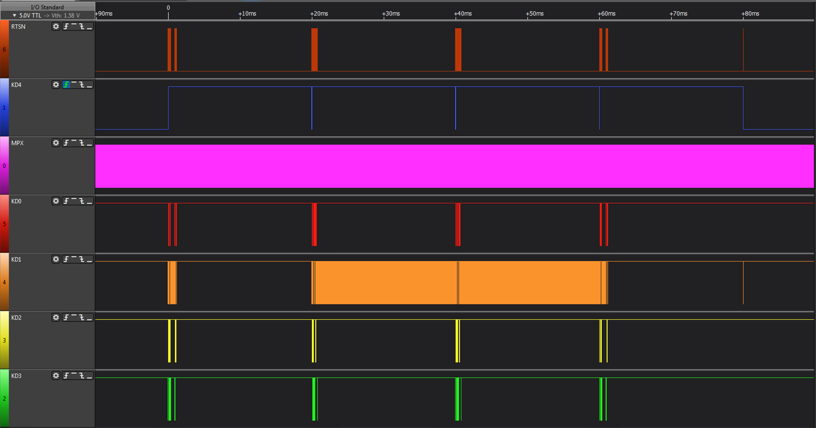
The signals can be visualised by the following logic analyzer diagrams below:
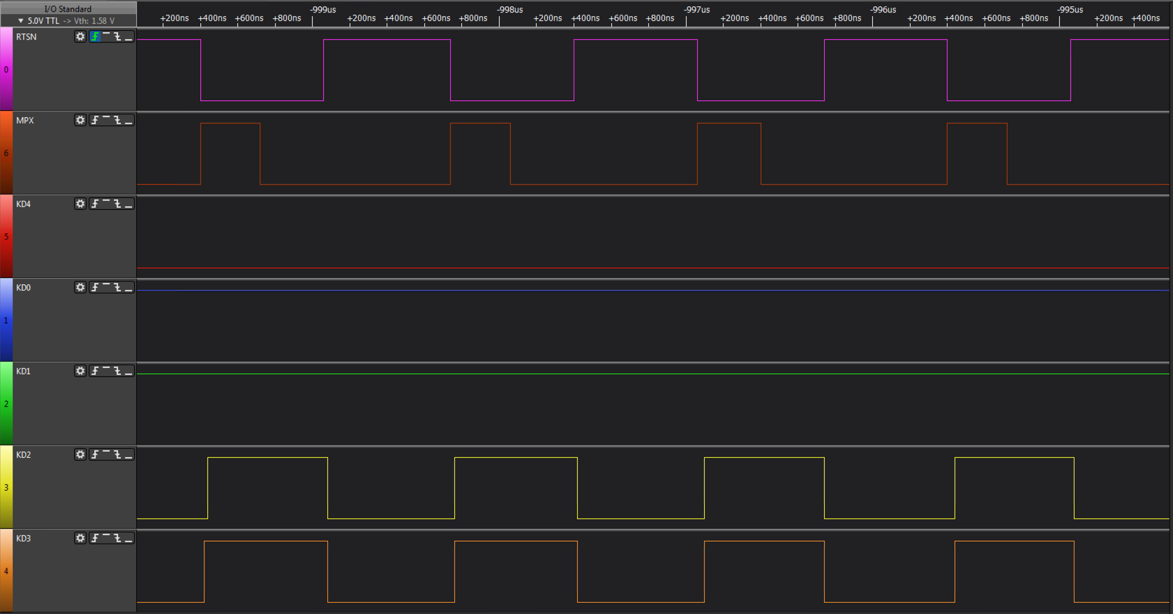
During inactivity, the gatearray on the mainboard sends a STROBEALL command, this is recognised by KD4 being LOW, the ROW, which is sent, isnt taken into consideration as the data returned is the logical AND of all keys in a given column across all rows.
When a key is pressed, detected by the STROBEALL, KD4 goes high and the mainboard starts probing the keyboard to determine which key was pressed. It starts by sending a request to return column data for Row 11, this row contains the special keys, CTRL, SHIFT, LOCK, KANA, GRAPH.
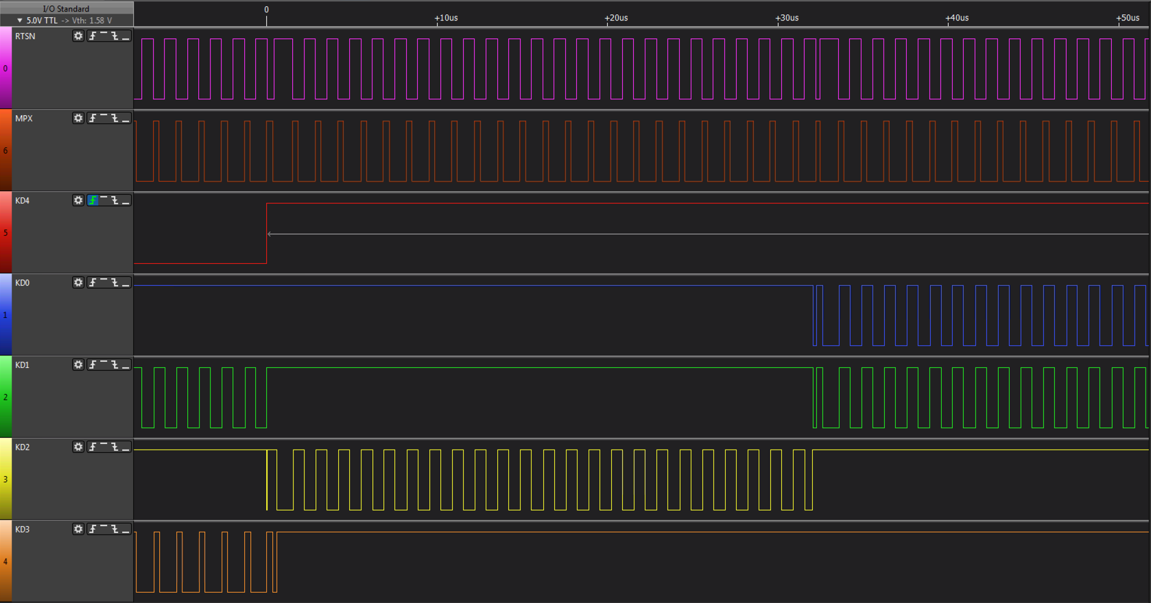
Scan of Row 11 takes place for around 30us, I believe this is to cater for switch bounce.
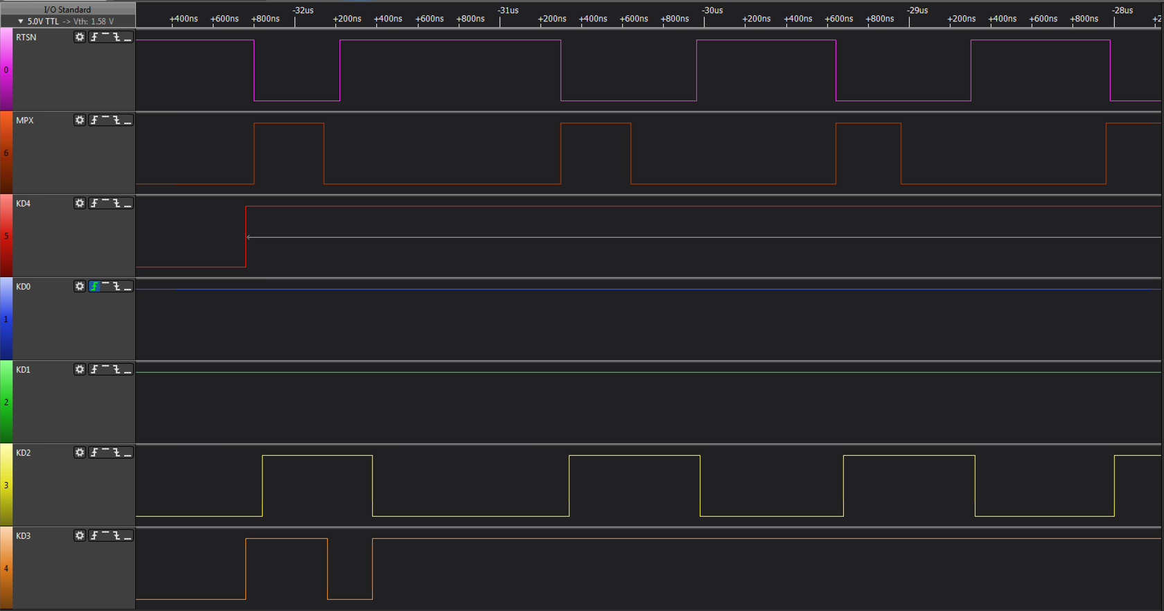
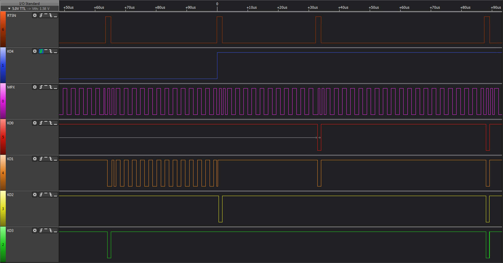
After probe of Row 11 it switches to Row 12 which contains the Japanese Transform keys. This can be seen on the left of the image, the wide RTSN pulse, look at the KD[3:0] values below and it will read 12 in binary. Row 12 is then scanned for around 50us.
Once row 11 and 12 have been probed, the mainboard commences a sequential scan of all the rows, starting at row 0, looking for the pressed key. Again look at the wide RTSN signal pulse and you will notice KD[3:0] incrementing.
The sequential scan continues until it locates the pressed key, which in this case is ‘C’ on Row 4 Column 3. The row is scanned for more than 600us to determine key bounce. The sequential scan of the remaining rows then continues and then it repeats from row 0 until the key is released.
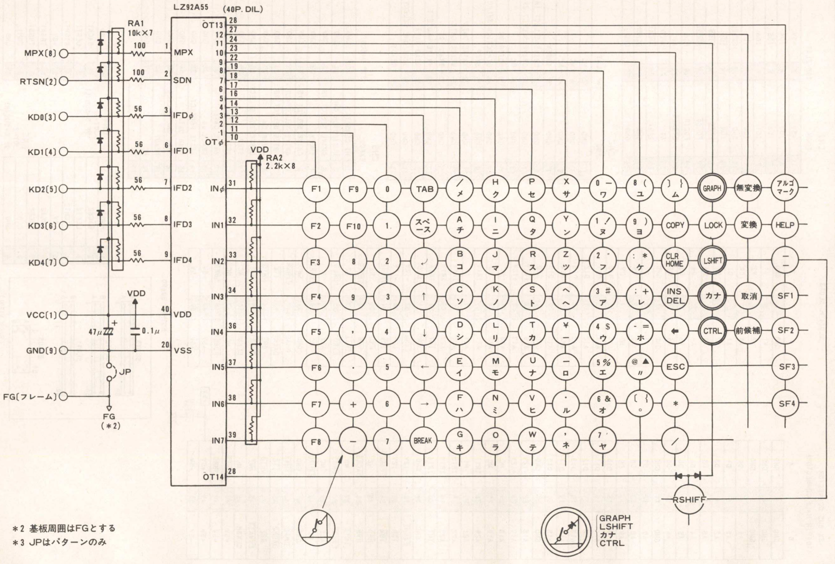
The hardware used by the MZ-2500 can be seen in the following two circuits.
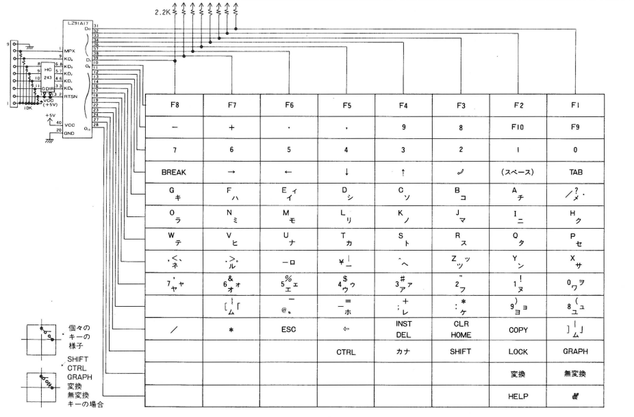
This schematic represents the keyboard circuitry which is composed of a gate array (or custom MCU, the part number doesnt reveal the type of device) and a bi-directional buffer. The gate array receives the row from the main unit and applies it to the keyboard strobe outputs. The key data is then read and returned under control of the MPX signal.
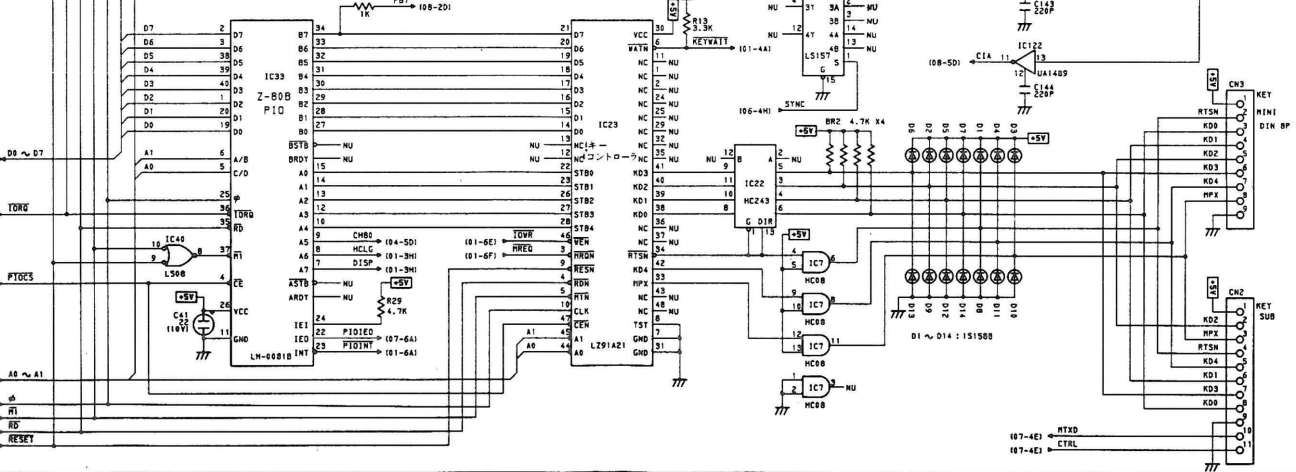
This schematic represents the main unit circuitry which comprises a gate array connected to the Z-80B PIO, which like the MZ-2000/80B expects to output a strobe row and read back an 8 bit value. The gate array appears to buffer the keyboard matrix internally so that Z80B PIO requests are acted on immediately. In order to do this, the gate array sends out a row number, 0 .. 13 and receives 8bit block of data, in 2 nibbles from the keyboard. It does this continuously, regardless of what the main computer is doing.
MZ-2800 Keyboard Protocol
The MZ-2800 is the successor to the MZ-2500 and its design incorporates an 8 bit Z80 based MZ-2500 mode and a 16bit 80286 mode which can run MS-DOS and other 16bit 80x86 based programs. Like the MZ-2500, the keyboard hardware interface comprises of 7 signals, 5V and GND but uses an obsolete AMP 9 pin USB style connector in a D-Sub housing. I have searched high and low for this connector or specifications on it but cannot find anything useful.
On the MZ-2800 motherboard is a standard low profile board to board 9 pin header which has the signals below, this is fed to a daughter board on which the AMP socket is mounted and then screwed to the outside casing. As I dont believe in hacking vintage equipment I searched for an alternative and found one (currently under development, which will appear here when proof tested), which uses a D-Sub with the same dimensions as the AMP connector so will screw onto the casing panel and will be a drop in replacement for the existing AMP connector. This solution means that should you ever be lucky enough to buy a real MZ-2800 keyboard, you can revert very quickly to the original AMP connector.
A recap of the signals are in the table below. They are identical physically to the MZ-2500.
| Signal | Direction | Logic State | Description |
|---|---|---|---|
| RTSN Row Strobe |
Main Unit -> Keyboard | HIGH (‘1’) | A Row address is being transmitted from the main unit to the keyboard. |
| LOW (‘0’) | The keyboard is transmitting requested data over the 4 bit bidirectional bus KD[3:0]. | ||
| KD4 Type Strobe |
Main Unit -> Keyboard | HIGH (‘1’) | The keyboard must return the actual key matrix data as referenced by the Row number. |
| LOW (‘0’) | The keyboard must return a logical AND of all the keys, ie. D0 = AND of bit 0 on ROWS 0 to 13, D1 = AND of bit 1 on ROWS 0 to 13 etc. | ||
| MPX Nibble MUX Strobe |
Main Unit -> Keyboard | HIGH (‘1’) | The upper nibble of the requested ROW (or AND of row data as directed by KD4) is sent from the keyboard to the main unit. |
| LOW (‘0’) | The lower nibble of the requested ROW (or AND of row data as directed by KD4) is sent from the keyboard to the main unit. | ||
| KD[3:0] Bi-dir bus |
Main Unit -> Keyboard | Active when RTSN = HIGH (‘1’), transmits the 4 bit row number of the row data from the keyboard matrix. | |
| Keyboard -> Main Unit | Active when RTSN = LOW (‘0’), transmits 4 bits of the 8 bit column data of the requested row. 4 bits is selected by KD4 & MPX. |
The protocol for the MZ-2800, although sharing the same physical signals as the MZ-2500, is a bit different, primarily timing. The same basic principles apply, ie. RTSN goes HIGH then a row number is sent to the keyboard, RTSN goes LOW then keyboard STROBEALL or data is returned. The essential difference is timing and the way the protocol is used to probe keys.
The primary protocol in both STROBEALL and key data retrieval modes is the same:
- RTSN goes active HIGH, the mainboard sends a scan row to the keyboard.
- Wait at least 200ns after RTSN goes active before sampling KD4 - KD4 trails RTSN
- Wait at least 650ns after RTSN goes active before reading ROW - KD[3:0] significantly trails RTSN.
- The scan row is read from KD[3:0]. In STROBEALL mode, as per the MZ-2500, the row repeats ad-infinitum with a constant value of 4 and doesnt appear to be used.
- KD4 is sampled, when LOW the logical AND of all keys per column is set for retrieval, when HIGH the actual column of the selected row is set for retrieval.
- Wait for RTSN to go inactive LOW.
- When MPX = HIGH the upper nibble of the data set for retrieval is output by the keyboard on KD[3:0] and read by the mainboard. When MPX = LOW the lower nibble of the data set for retrieval is output on KD[3:0]. MPX has the same period as the MZ-2500, ie. 640ns, 320ns active HIGH and 320ns LOW.
- The above repeats, the row sent can vary or remain static, for example if reading the same key to determine bounce or repeat.
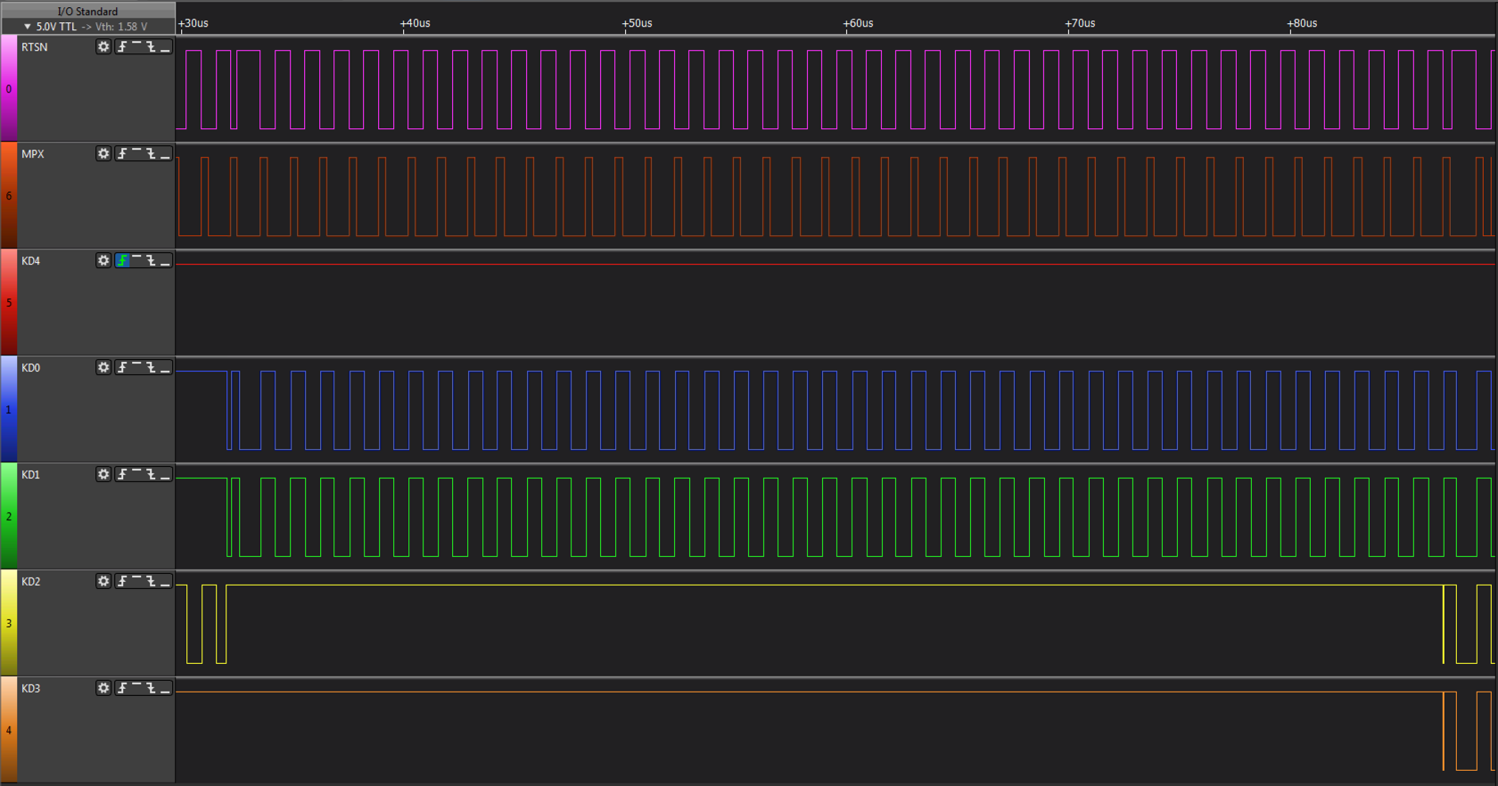
STROBEALL mode, the mainboard is waiting for a key to be pressed so it holds KD4 LOW. The row sent in this diagram is row 0 but it has no obvious purpose as STROBEALL mode logically AND’s all rows for a given column together.
Once a key has been pressed, the mode changes to key retrieval mode. KD4 goes HIGH and the mainboard starts sending valid row numbers to retrieve column data. As per the MZ-2500, row 11 is interrogated first followed by row 12 and then a sequential sweep from row 0 occurs.
The timing delay between RTSN going active and row data being available can be seen in this diagram. Unfortunately I seem to have mislaid the timing diagram showing KD4 trailing RTSN, next time I rig up the logic analyser I will snapshot it.
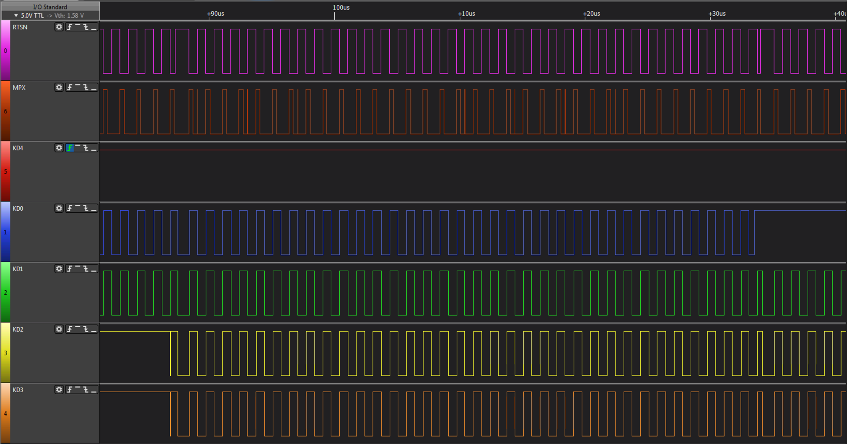
The sequential scan can be seen in the image above.
The sequential scan can be seen here. When the scan reaches the row of the pressed key (‘C’ - row 4 column 3) the same row is read for 100us to cater for debounce before the scan continues.
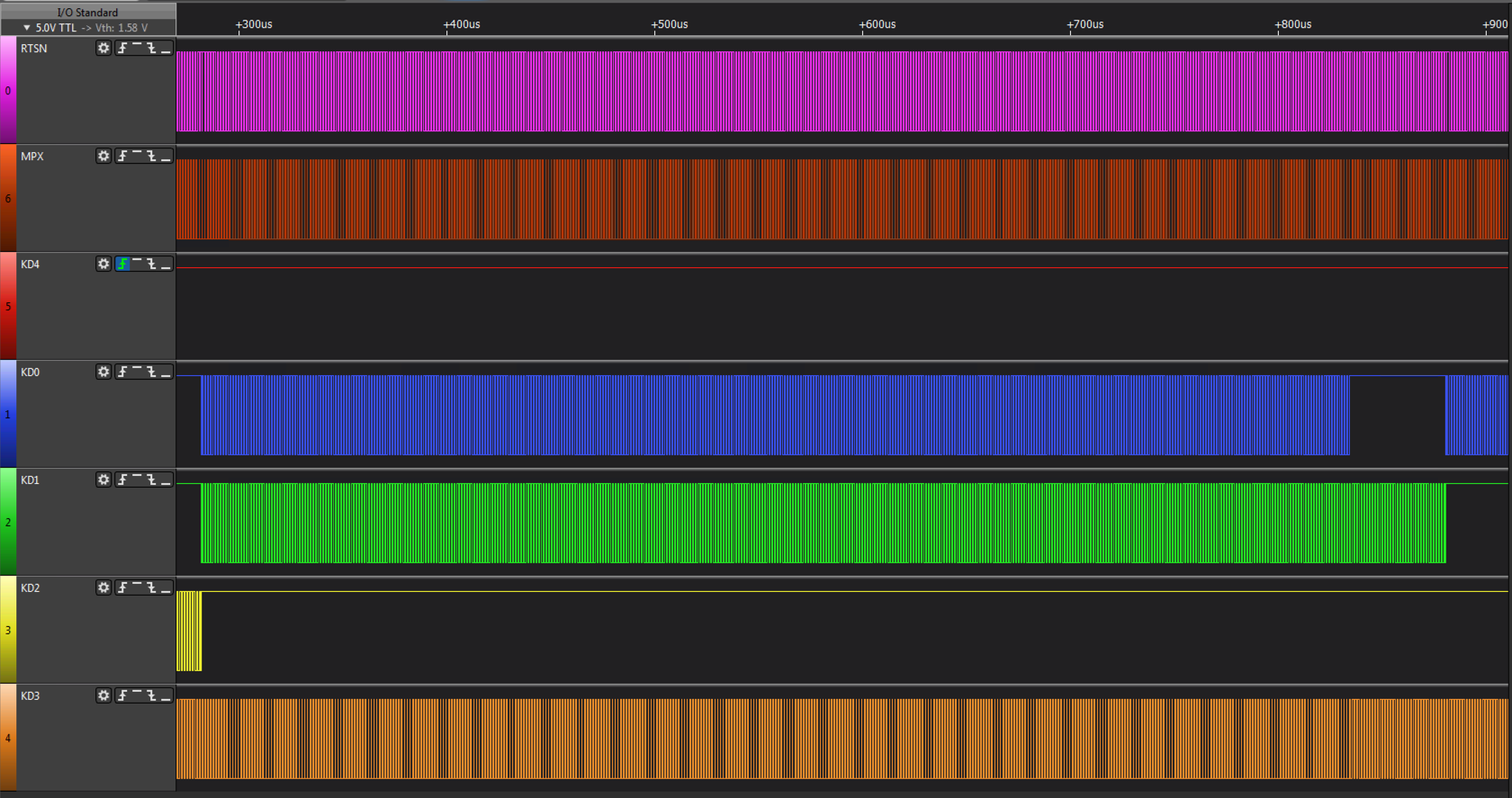
The sequential scan repeats whilst a key is being held down. When the scan arrives at the pressed key a second time it sans for over 300us before proceeding (NB. Key ‘A’ pressed in example above).
A full cycle, where a key press is detected until the moment it is released.
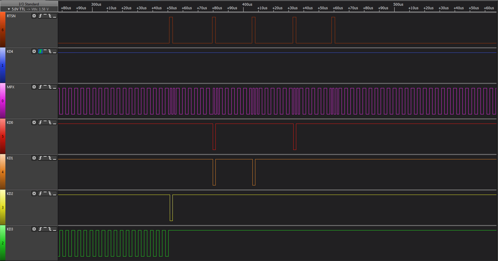
One of the differences between the MZ-2800 keyboard and the MZ-2500 keyboard is the addition of a 14th row, scan of which can be seen above. On the MZ-2800 in MZ-2500 mode, row 14 isnt scanned, it is only scanned when in MZ-2800 mode.
The hardware used by the MZ-2800 can be seen in the following two circuits.
This schematic represents the keyboard circuitry which is composed of a gate array (or custom MCU, the part number doesnt reveal the type of device) and a bi-directional buffer. The gate array receives the row from the main unit and applies it to the keyboard strobe outputs. The key data is then read and returned under control of the MPX signal.
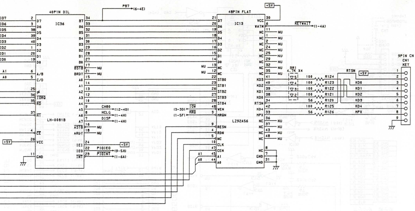
This schematic represents the main unit circuitry which comprises a gate array connected to the Z-80B PIO, which expects to output a strobe row and read back an 8 bit value. The gate array appears to buffer the keyboard matrix internally so that Z80B PIO requests are acted on immediately. In order to do this, the gate array sends out a row number, 0 .. 14 (13 in MZ-2500 mode) and receives 8bit block of data, in 2 nibbles from the keyboard. It does this continuously, regardless of what the main computer is doing.
ESP-32S AI Thinker
Looking at some of my evaluation boards, I started to venture on using a Gowin G1WN-4NSR FPGA, the best solution as everything would be done in hardware with finite state machines and no restrictions to meeting the tight MZ-2500 timing as I would be working at gate level not microcoded CPU instructions. The G1WN-4NSR also embeds an ARM Cortex-M3 which could have been used for configurable mapping. Unfortunately I was having a lot of issues programming the device from a Virtual Linux Machine running on a Mac and with no native Mac support I had to give up on the idea.
A few years back I tinkered with the ESP-8266 from Espressif and closely followed the development of it's 32bit product, the ESP-32. I bought 5 sample units from AI Thinker (ESP-32S WROOM) two years back intending to use them with my tranZPUter project but for various reasons I ended up using the ARM Cortex-M4 from NXP. The ESP-32's thus lay idle, until now, a case of a solution looking for a problem and one had been found, a PS/2 to MZ-2500 interface! Digging out and reading the data sheet, looking at available hardware and software resources such as libraries (ie. PS/2) and the development eco system, the ESP-32 seemed to fit the requirements of this project. It had a rich library and development system through use of the Arduino platform and also its own CMake/Ninja IDF build environment. I initially looked at using Arduino as it has a lot more libraries but after a while it became obvious Arduino was a limitation in that I needed to dedicate one CPU core to the MZ-2500 side of the interface whilst the second core serviced the PS/2 keyboard in order to meet required timings. The setup of FreeRTOS under Arduino didnt easily allow for detaching a core (using FreeRTOS spinlock or disabling interrupts within a core and setting FreeRTOS to not schedule tasks on a core didnt work). I spent quite a bit of time looking for a solution and eventually decided to use a more native FreeRTOS environment which was offered by Espressif using FreeRTOS and a lot of their own support libraries under the CMake/Ninja build system. Having worked with CMake/Ninja n the past, including the Linux Kernel build environment, I felt right at home and decided to progress on this path. A few configurations later, one core was detached from FreeRTOS (using a spinlock) running a permanent tight loop to manage the MZ-2500 interface whilst the other core read PS/2 codes and assembled a virtual matrix. After all this analysis and investigation, the decision was made to base the interface on an ESP-32S dual core SoC using FreeRTOS under Espressif's development eco system.
Next decision, how should the interface be constructed? The solution immediately became apparent after building several of Martin's @ 8bity.cz X68000 interfaces. I would use a KM-24 case, small compact and neat. A quick mockup of an ESP-32S and some other components on an unused X68000 board, it all seemed to fit into a KM-24 case, so started the actual prototype design!
Schematic
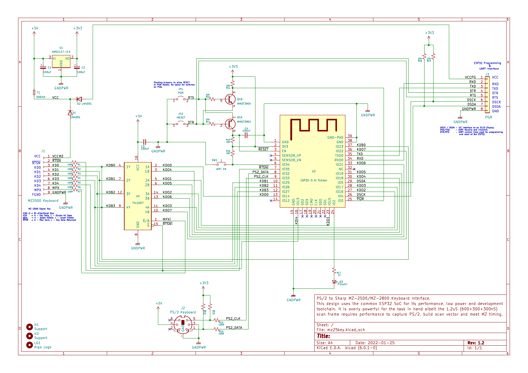
The device is 5V tolerant but operates at 3.3V, so the obvious choice for the PSU, having used them for the tranZPUter and had plenty in stock, was the AMS1117 3.3v converter. It is relatively efficient, only dropping 1.1v at approx 30mA (150mA if the WiFi mode is enabled) and supplies a stabilised low ripple output. Under normal conditions the device would be powered from the MZ-2500 keyboard interface but on occasion it will need to be connected to a programming interface. In order to avoid 'mistakes', connecting the MZ-2500 and programming interface simultaneously, rectifier diodes are used to isolate the two power sources. A fuse is also used to protect the MZ-2500 should something go faulty or a short occur during development and probing.
The programming interface is very simplistic (no convoluted ARM Cortex programming here), two serial wires from a 3.3/5V UART. In order to work seamlessly with the Espressif IDF build and programming system, an automated bootstrap circuit (Q1A/B) is added and driven by RTS/DTR, this allows the build system to place the ESP-32S into programming mode, program it and then force a reset. Makes for very easy development, CI/CD eat your heart out!!!
The PS/2 interface is a standard design used in Espressif solutions. 2 bi-directional pins driving a PS/2 keyboard with a protocol similar to I2C. The ESP32 can sink/source sufficient current to meet the PS/2 specifications without need for additional transistors.
As the timing of the MZ-2500 interface is time critical and 2 nibbles need to be delivered 300ns apart, I thought it prudent to drive out a byte from the ESP32 into a 2-1 multiplexer under control of the MZ-2500, so the timing requirements were lessened. On detection of the RTSN signal going high the ESP32 would read in the row number, lookup the matrix value (built up from incoming PS/2 keys) and output a byte to the mux. Resistors are added on all the MZ-2500 signals to limit current and reduce line reflection.
Given the potential power of the ESP32 I added an additional switch to allow enabling of the onboard WiFi transceiver. Normally this would be powered down to conserve power and to prevent interference but I have the intention to allow this device to be configured OTA. Under normal circumstances, if I find a key mapping which hasnt been configured then it is a quick fix by editting the source and recompiling, but it would be nice to be able to change a key mapping via a web browser.
The beauty of this ESP-32 design is it could quite easily be used for other machines, ie. X1 or X68000 as 5 bidirectional signals and 1 input provide the option, with a different cable and firmware, of driving these machines.
If the interface is constructed for an MZ-2800 then the cable end differs, on an MZ-2500 it is an 8pin mini-din whereas on the MZ-2800 with the alternative connector, it is a D-sub connector.
PCB
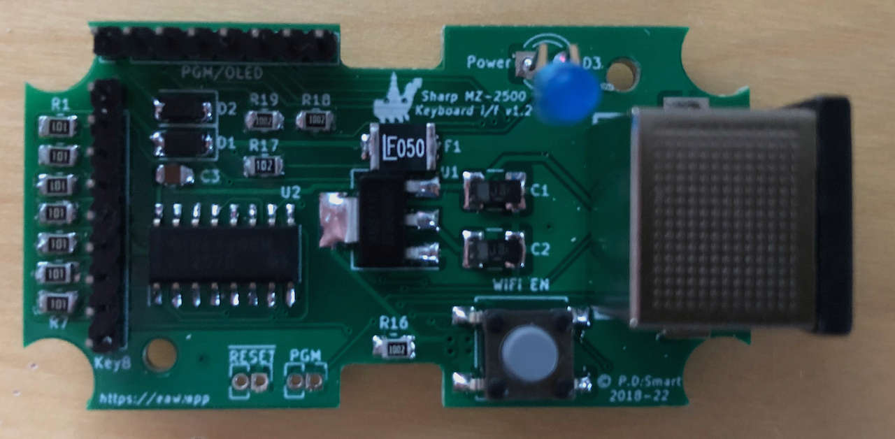
Having prototyped the designed circuit and written the majority of it’s control software, I set about designing the PCB. It had to be small to fit inside a KM24 case and given the number of components and size, both sides of the PCB needed to be used.
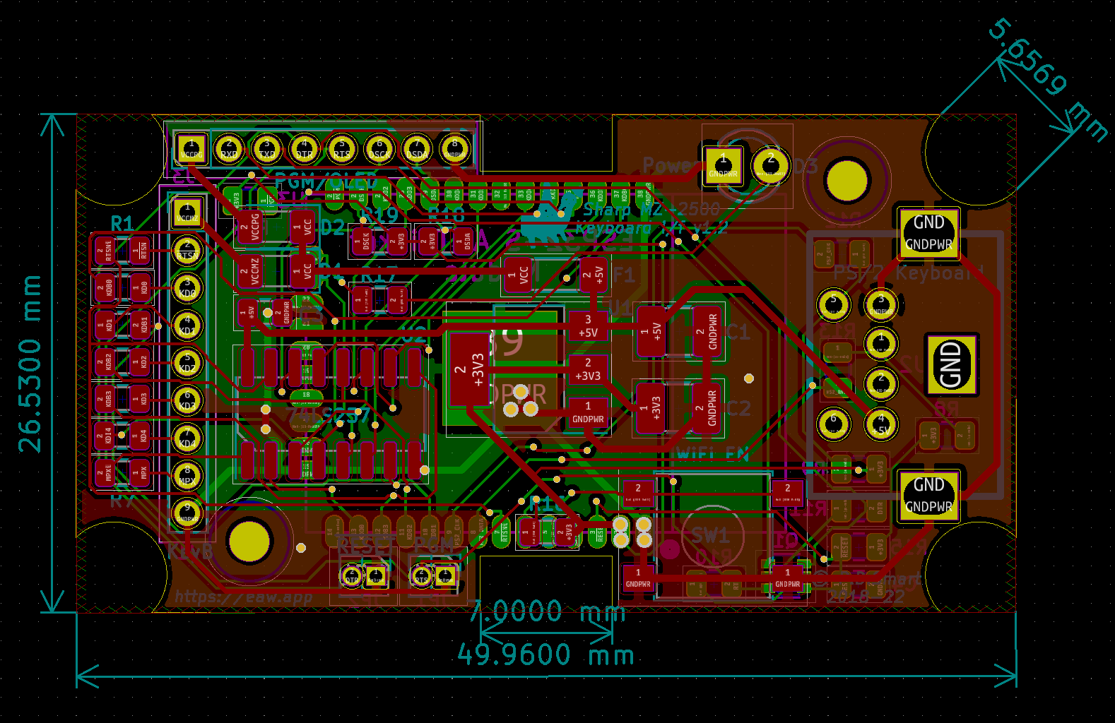
The finished circuit board which went into fabrication.
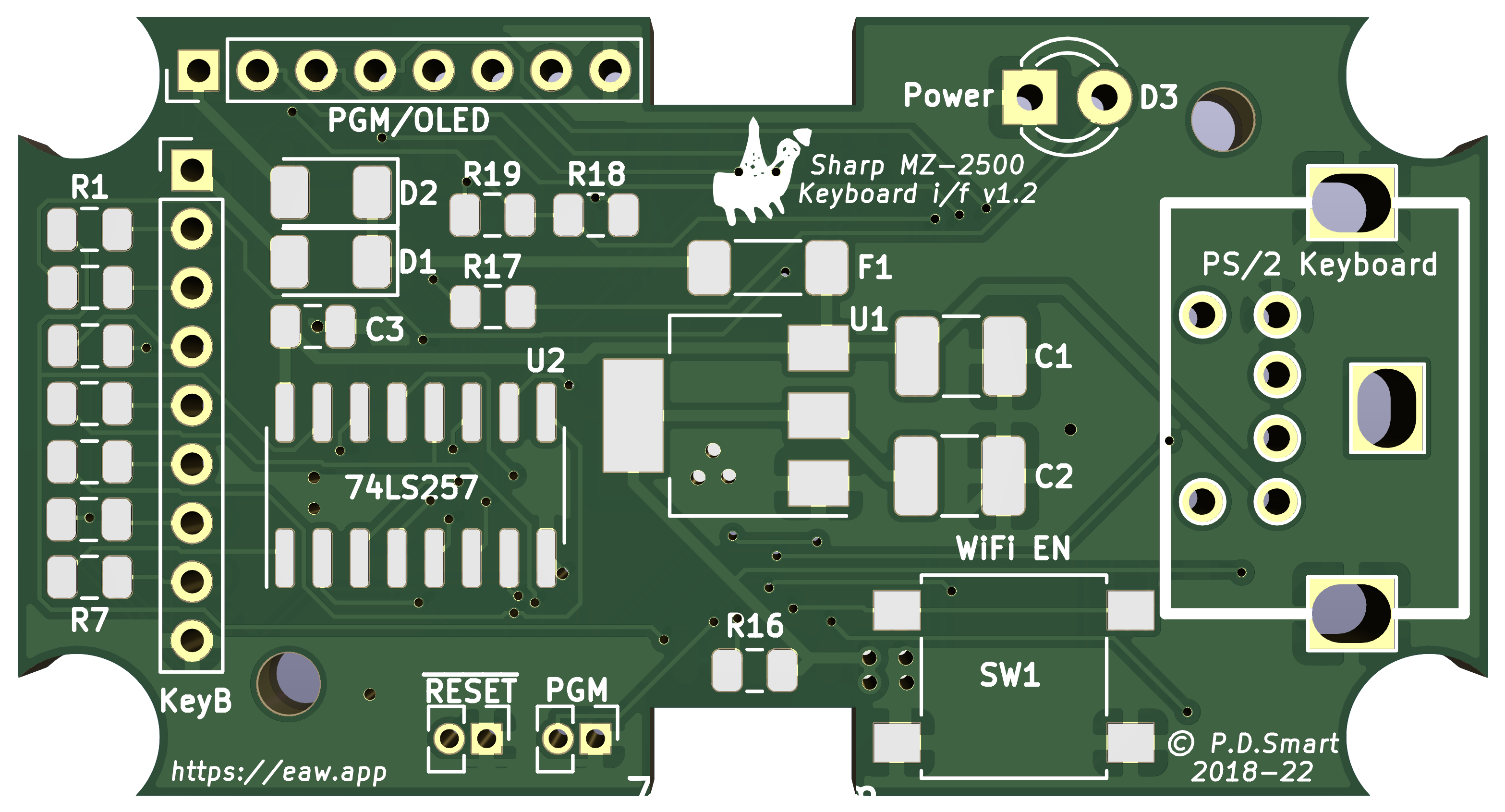
Assembled Interface
The pictures below highlight the completed, assembled and working interface.
Top side of the interface, there are some optional components installed such as the 2mm pin headers, the 8pin programming interface is needed but the 9pin MZ2500 interface header can see the cable directly soldered to the board. There are optional 1.27mm headers for manual RESET and Programming (PGM)
modes but these arent needed under normal use (unless you use a UART without DTR/RTS in which case they are needed).
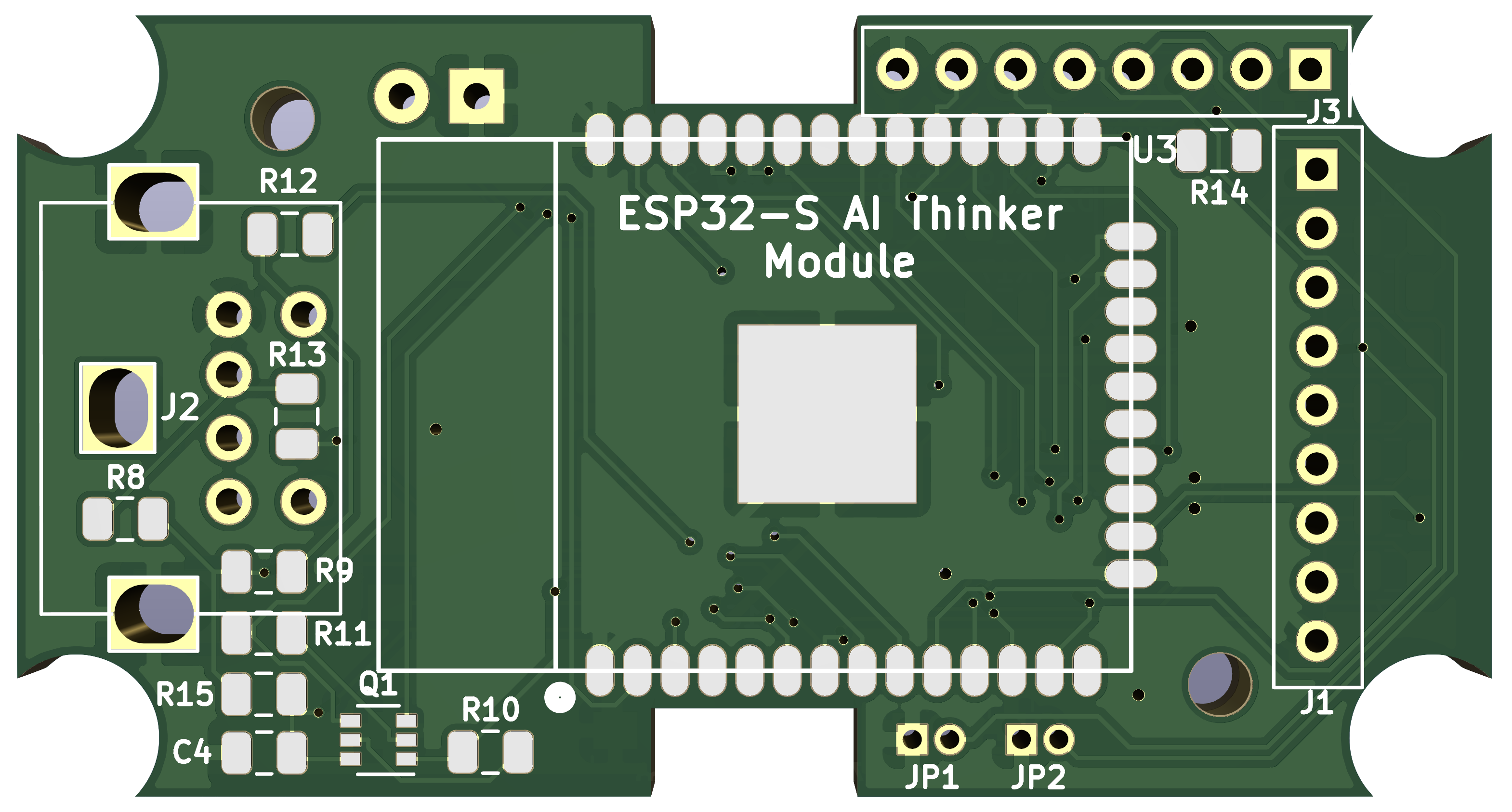
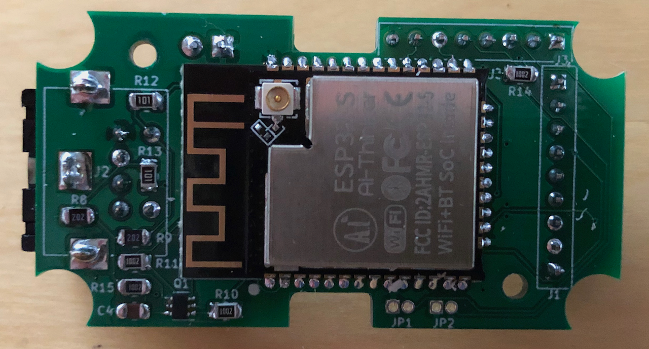 The underside of the interface, the ESP32 takes up most of the space. What looks like solder bridges on some of the pins is actually the ABS plastic from the case as I test assembled it before cleaning the drilled case!
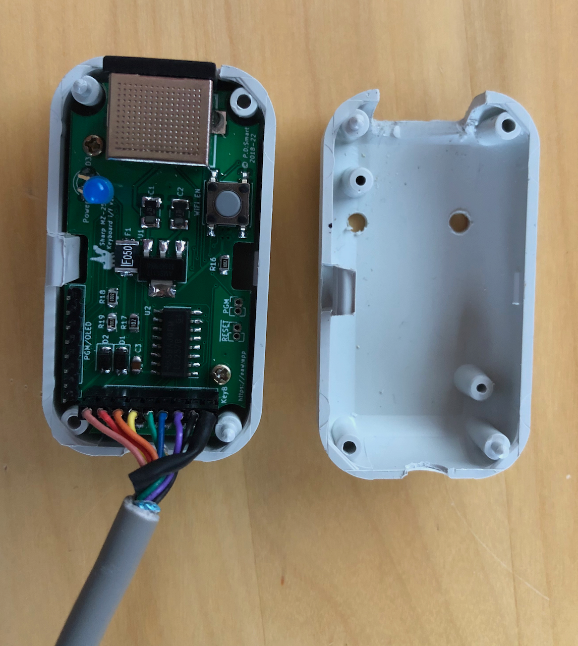 Installation inside a KM-24 case, tight fit and the case cutouts could be more professional (hint to diary, need more tools!).
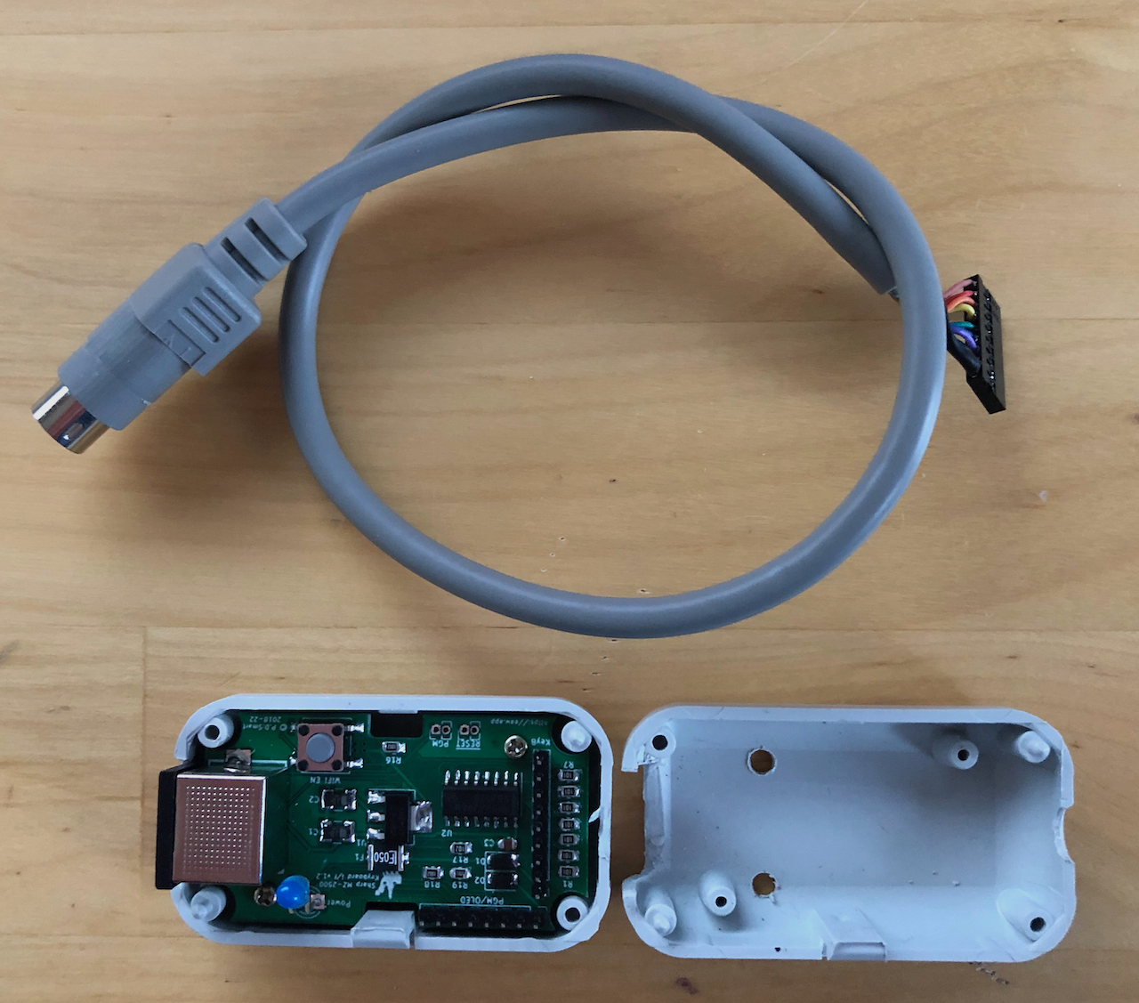 By using pin headers it is possible to disconnect the pre-made 8pin mini din cable, either to change it (for example to an MZ-2800 cable) or develop the firmware to drive another machine, ie. the X1. The X1 only needs GND, 5V and 1 bi-directional pin so would work well.
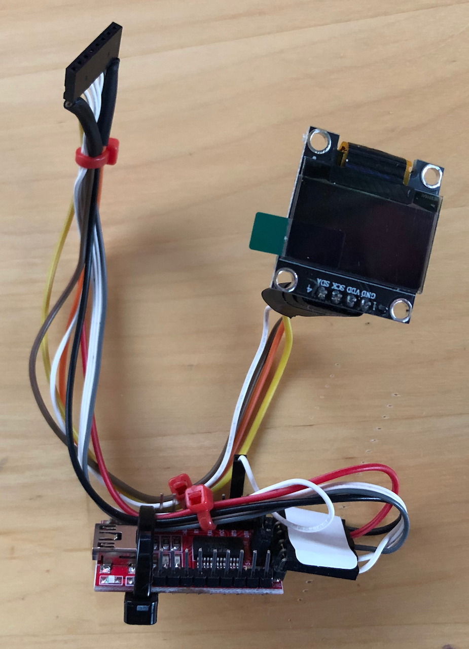 The programming harness. This comprises a generic USB to TTL UART adapter, an optional OLED display to output the current key matrix and the 2mm header to plug into the interface.
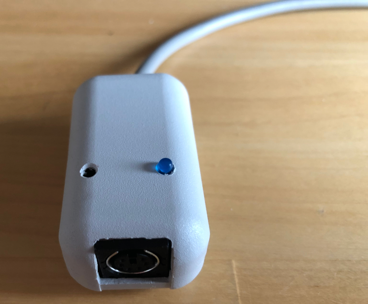
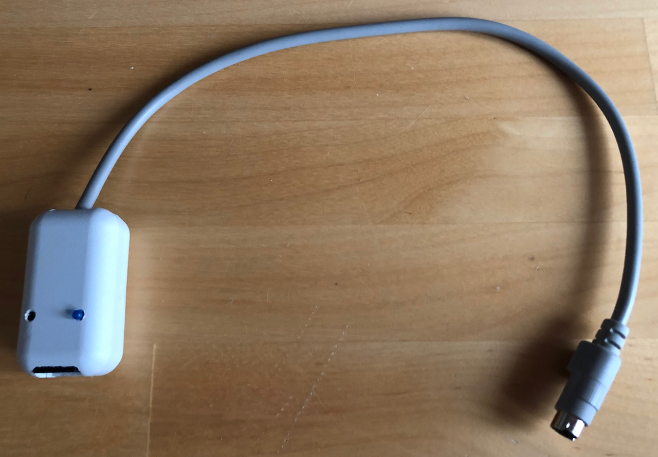 Finished product, ready to be used with an MZ-2500. I am still looking at options for the MZ-2800 as the interface works but the strange AMP 9 pin socket can no longer be sourced so need to think of a non-destructive solution, perhaps change the socket on the MZ-2800 for an 8pin mini din.
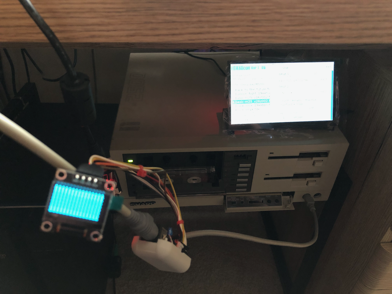 The interface connected to my MZ-2500 during development. The OLED screen is used to display the virtual key matrix.
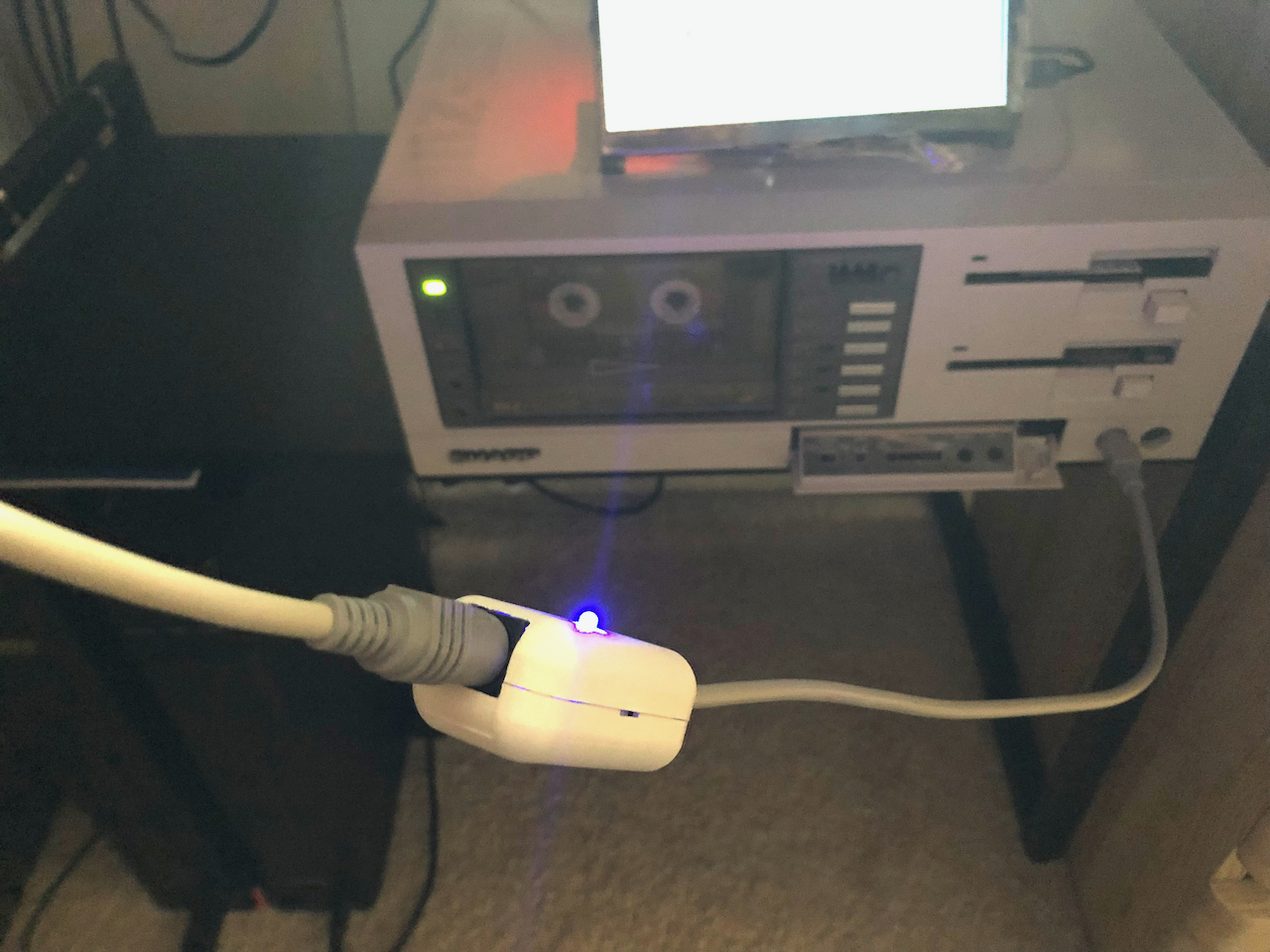 The completed interface connected to my MZ-2500.
Assembled MZ-2800 Interface
The MZ-2800 as shown earlier uses what appears to be the same hardware interface as the MZ-2500 but the protocol and its associated timing is different. The MZ-2800 also used a different keyboard plug and socket, instead of the 8pin mini-din chosen on the MZ-2500, Sharp decided to use a chunkier AMP 9 pin D-Sub plug and socket, presumably to make it sturdier. Unfortunately the 9pin AMP D-Sub went the way of the Dodo and can no longer be sourced, at least from all the major vendors and also ebay! This required sourcing an alternative, bodging wasnt an option, ie. hacking wires onto the mainboard to circumvent the connector.
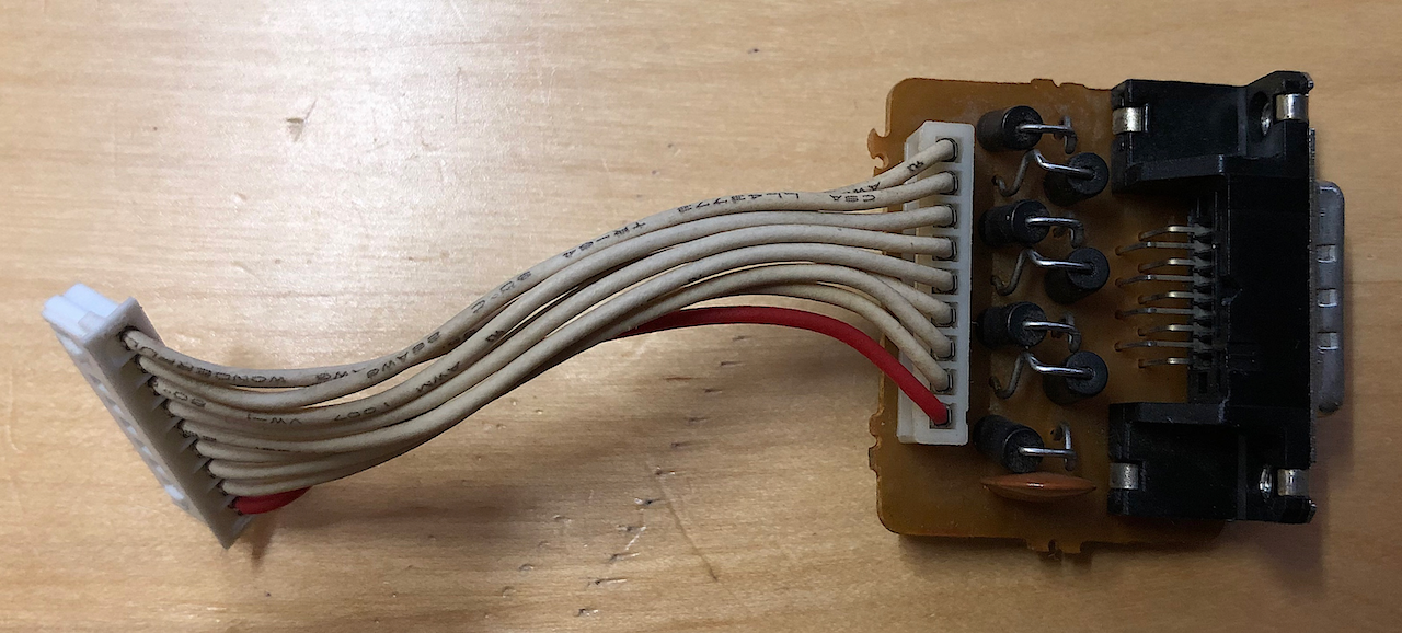 The MZ-2800 used a 9 pin AMP socket which is no longer available so an alternative had to be found. Also the mainboard JST header into which the leads from the AMP connector plug is no longer available. The mainboard 9pin male header uses spade terminals whereas JST now only seem
to sell connectors with the more standard square needle terminals. The solution is to replace the mainboard 9pin header (CN1) with a JST XH2.50mm which has the advantage of still working with the original AMP socket as the square pins fit into the spade receptacles on the AMP daughter board plug.
The MZ-2800 used a 9 pin AMP socket which is no longer available so an alternative had to be found. Also the mainboard JST header into which the leads from the AMP connector plug is no longer available. The mainboard 9pin male header uses spade terminals whereas JST now only seem
to sell connectors with the more standard square needle terminals. The solution is to replace the mainboard 9pin header (CN1) with a JST XH2.50mm which has the advantage of still working with the original AMP socket as the square pins fit into the spade receptacles on the AMP daughter board plug.
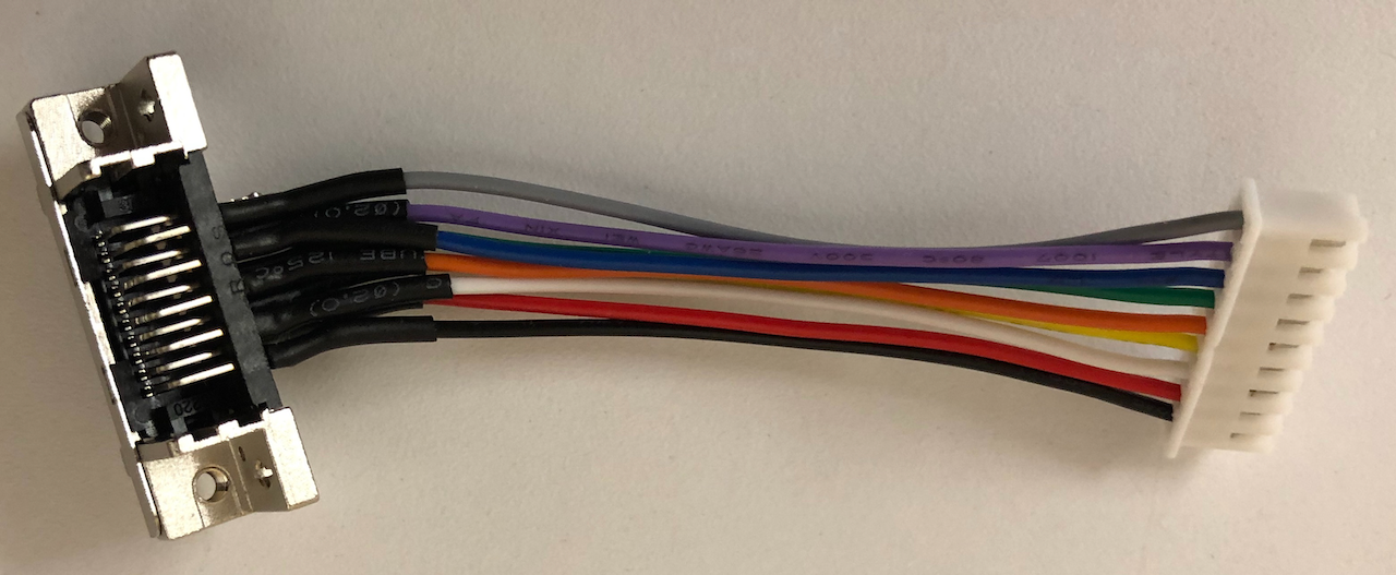 A look through various parts catalogues located a compatible socket and plug made by 3M, namely 10120-6000L plug and 10220-5212PL socket. These are 20 pin devices but with the exact dimensions to fit and mount onto the MZ-2800 casing. The socket was wired up to a JH 9pin header socket
allowing the assembly to replace the original.
A look through various parts catalogues located a compatible socket and plug made by 3M, namely 10120-6000L plug and 10220-5212PL socket. These are 20 pin devices but with the exact dimensions to fit and mount onto the MZ-2800 casing. The socket was wired up to a JH 9pin header socket
allowing the assembly to replace the original.
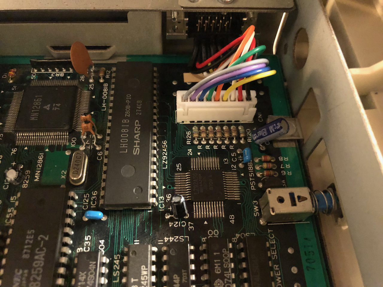 The socket fits perfectly into the case, the new socket being threaded made the job easier, just two screws to fasten it onto the case wall. The short leads of the assembly connect into the CN1 mainboard header socket.
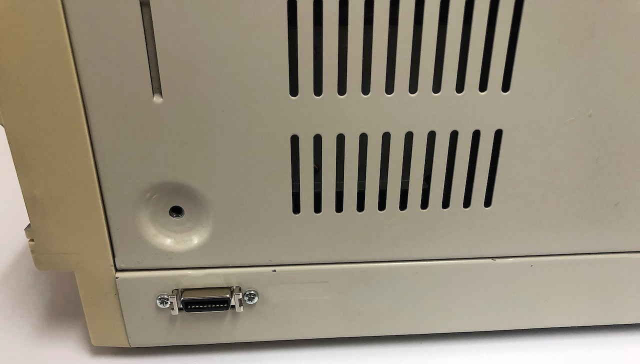 The socket on the case exterior, just need to make up the interface and plug.
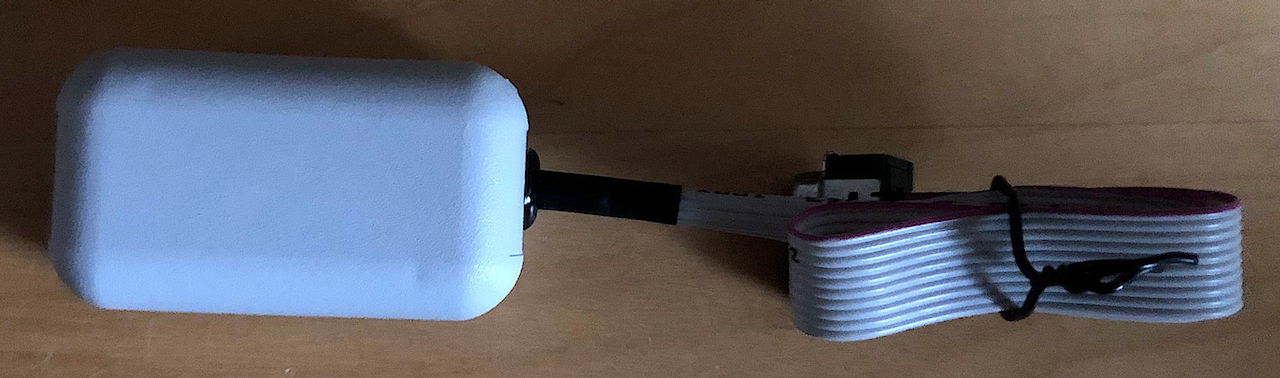
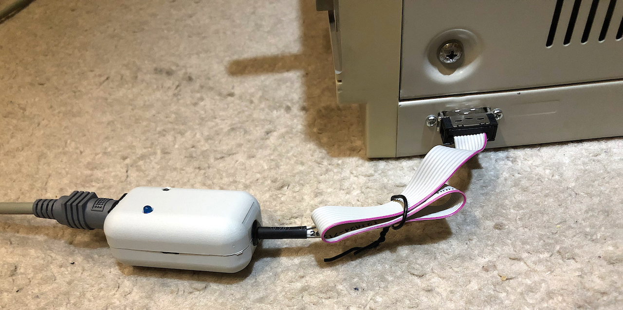
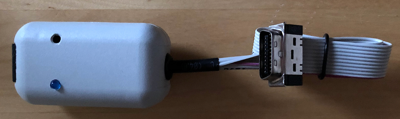 Taking an MZ25KEY interface, a short length of ribbon cable and an IDC plug, the MZ-2800 interface was finally assembled. The firmware loaded into the interface is specific to the MZ-2800.
 The underside of the interface.
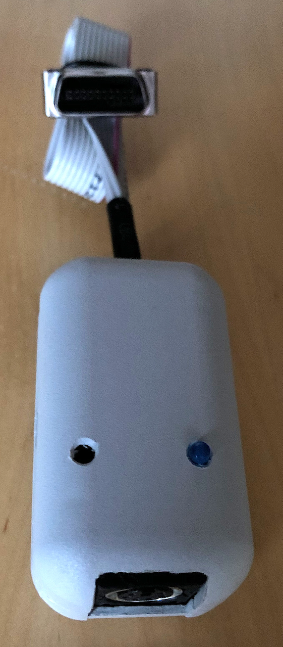 A one eyed mouse with a snake head?
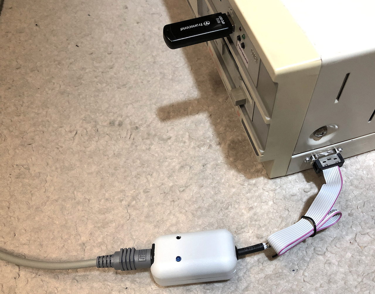 Testing, the PS/2 keyboard plugs into the interface and the interface then plugs into the MZ-2800.
 Job done!
Firmware
The firmware is written under the Espressif IDF build system comprising of gcc(++) git, CMake and Ninja. The build system works under Windows, Linux or MacOS but in this instance, Linux was used. It has the Arduino compatibility component installed as the PS/2 Library was originally written for Arduino. The firmware is written in a mix of C and C++ with C++ being the primary language.
Firmware installation
Use git clone to pull the software repository onto your computer.
git clone https://github.com/pdsmart/mz25key.git
Build System Installation
To create an Espressif IDF build system, follow the guides from Espressif as follows:
- Ensure you have python v3.7 or higher installed. Once installed, use ‘update-alternatives’ to select the latest version as the primary interpreter, some Linux installations default to the older universal version of Python, v2.7.
- Install the Espressif repository using this guide. Be sure to either install v4.4 with the ‘-b v4.4’ flag on ‘git clone’ or use ‘git checkout’ after clone. v4.4 is needed for Arduino compatibility module support. If you install the IDF for system wide use, ensure write settings are changed so that your user, not root, has write access for the next step.
- Install the Espressif Arduino compatibility module support using this guide.. Do this under your own user id or the one you will develop with and in the mz25key directory cloned earlier where you will compile the mz25key interface firmware.
Firmware compilation
After pulling the repository from git and installing the Espressif IDF you will need to configure the project. A KConfig file, ‘sdkconfig’ is included with the firmware but you may want to change some of the options. This can be accomplished by the command:
idf.py menuconfig
This will lead to a set of menus as highlighted in the images below.
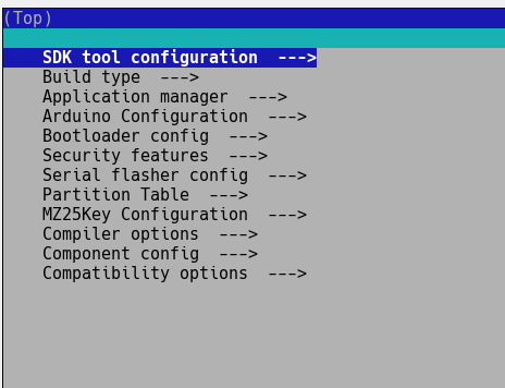
The root screen allows to configure various aspects of the Espressif IDF installation, the compiler, ESP32, FreeRTOS settings etc. Many settings can be changed but for the interface, the ‘MZ25Key Configuration’ option should be selected.
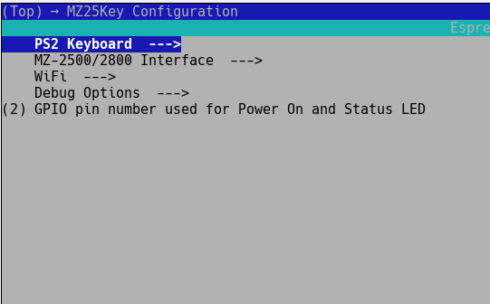
You have the option to configure the PS/2 Keyboard interface, the MZ-2500/2800 interface, Wifi and Debug options.
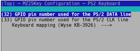
In the PS/2 configuration, you can set the GPIO pins used for the interface, unless you have built your own board and used different GPIO’s these dont need changing.
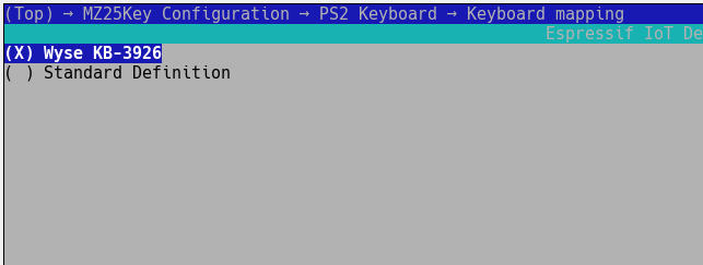
The other option to select under the PS/2 menu is the type of keyboard mapping, currently there is only the mapping for a Wyse KB-3926 keyboard.
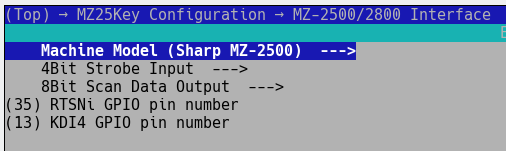
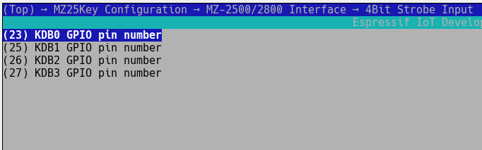
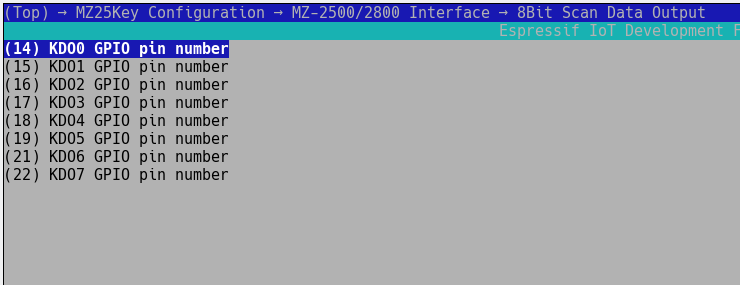
Under the MZ-2500/2800 Interface menu, you can select the target machine (MZ-2500 or MZ-2800) and also configure the GPIO’s used for strobe input, scan data output and the RTSN/KDI4 inputs. These dont normally need changing unless building different hardware.
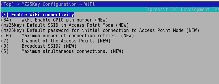
Under the WiFi menu, currently a work in progress, you can enable the Wifi module and set the various default parameters.
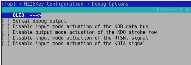
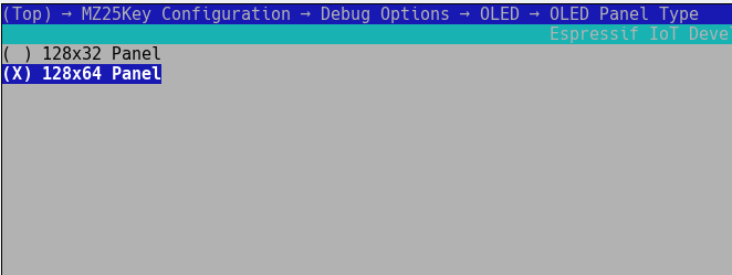
Under the debug menu you can enable various debug aids. The OLED screen, if connected, can be useful for outputting real time data. You can also disable various components of the interface for testing. The ESP32, by default, outputs text messages via the serial port, so if a USB to TTL UART adapter is connected to the programming connector, these messages can be viewed. The ESP mechanism includes a logger to output text to the UART.
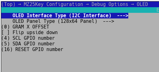
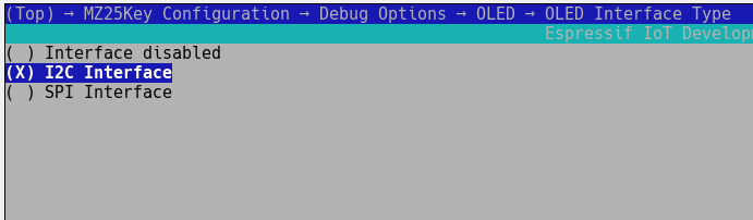
The OLED type needs to be configured. The hardware accommodates an I2C interface and the resolution is 128x64 pixels.
Once configured, perform a test build via the command:
idf.py build
If all is successful, connect a USB to TTL UART adapter to your computer and connect it to the mz25key interface programming connector. The wiring is as follows:
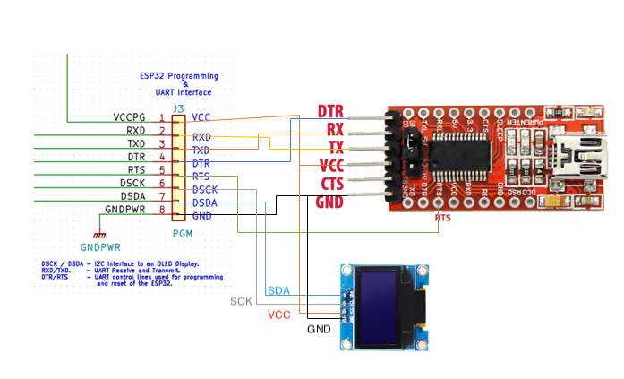
Obtain the dev port of the USB to TTL UART adapter by looking in /dev for ttyUSB* devices, normally it would be /dev/ttyUSB0. Perform a full build, flash and monitor via the command:
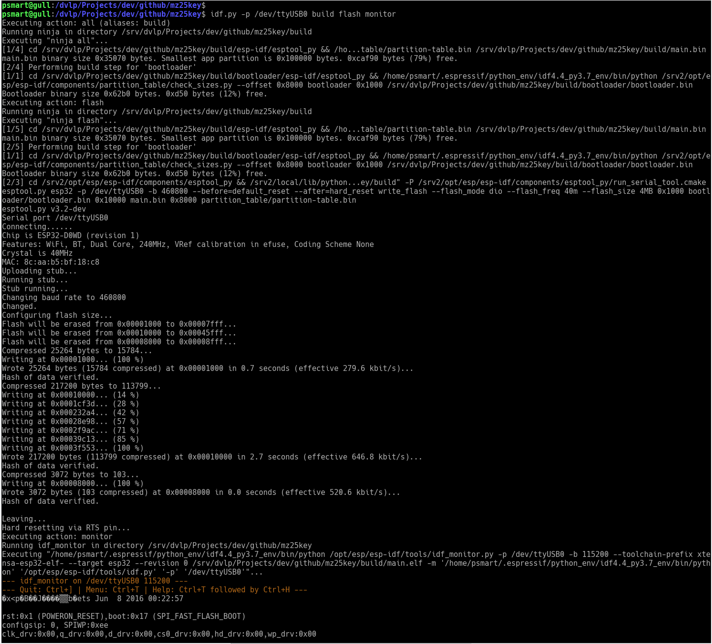
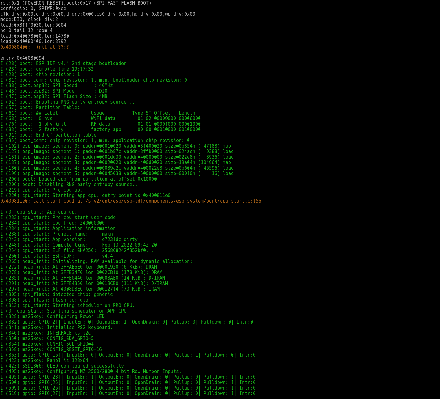
idf.py -p /dev/ttyUSB0 build flash monitor
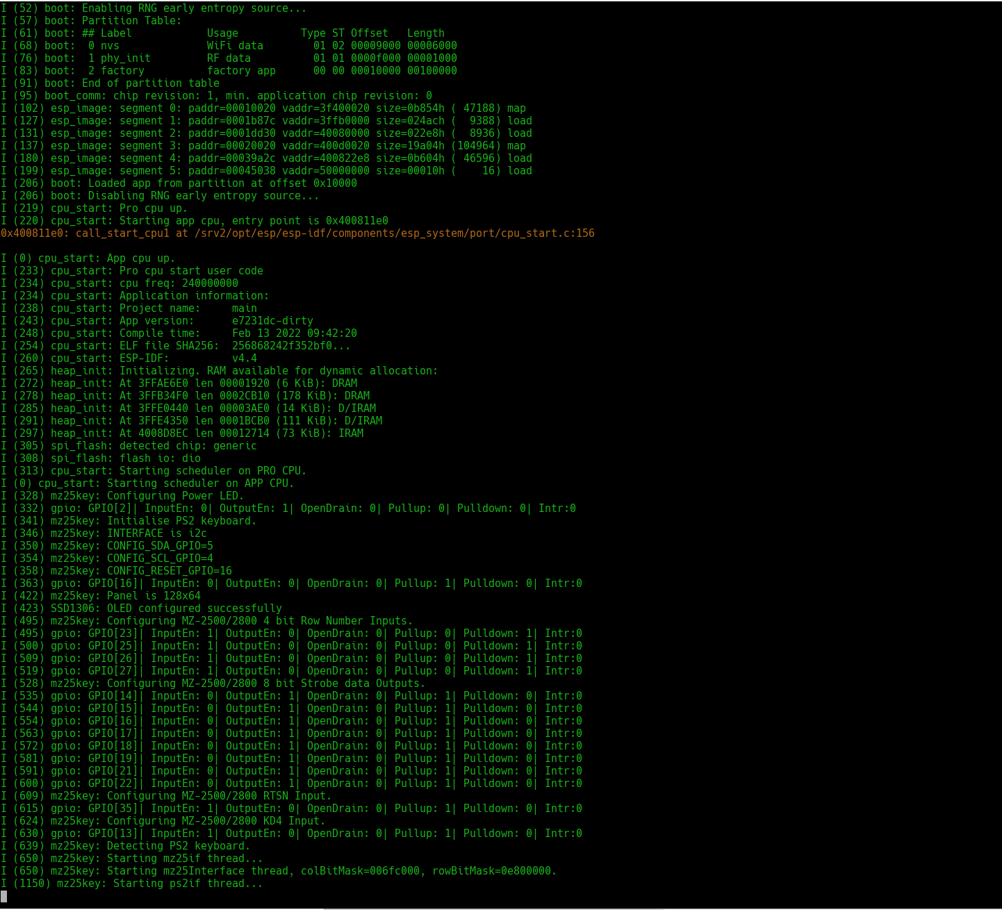
The system will compile the firmware, flash it onto the mz25key interface and run the UART monitor so you can view any messages output. ie:
Usage
A keyboard is a keyboard, right? Well, not exactly, especially when one keyboard is pretending to be another!
A PS/2 keyboard was created for an IBM PC or compatible several years after the advent of an MZ-2500/MZ-2800, also the keyboards I have access to are not Japanese PS/2 units, so several Japanese specific keys are missing. This requires mapping, selecting an unused key on the PS/2 keyboard to pretend to be a Japanese key on an MZ-2500/MZ-2800 keyboard.
As the MZ-2500/MZ-2800 machines are an office cream colour in appearance and having previously used Wyse keyboards in the past, I opted for a Wyse KB-3926 cream model to best match the MZ. The MZ-2500, MZ-2800 and Wyse KB-3926 keyboards can be seen below and the mapping table, mapping PS/2 keys to MZ-2500 keys appears below.
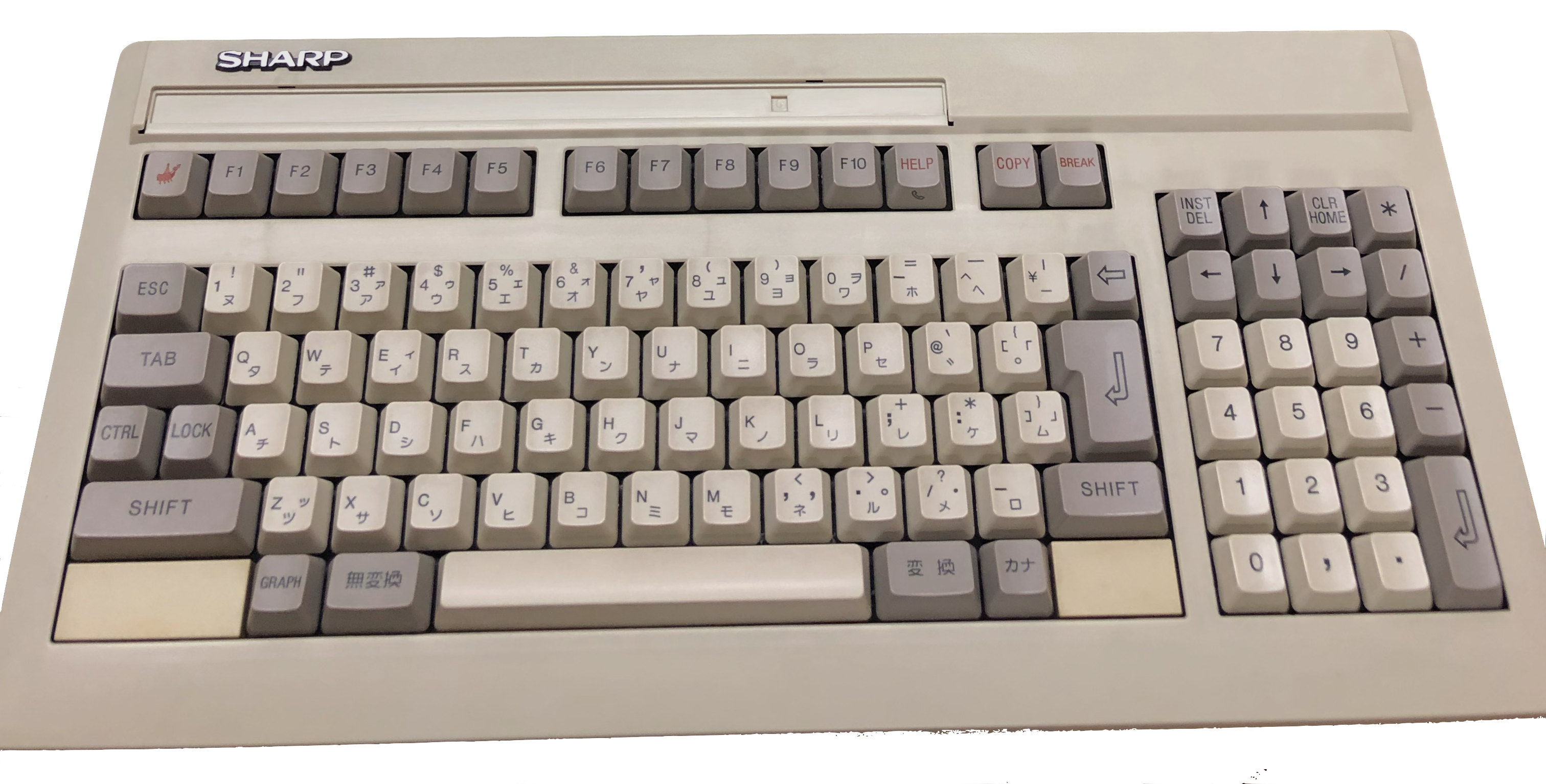 Original Sharp MZ-2500 keyboard.
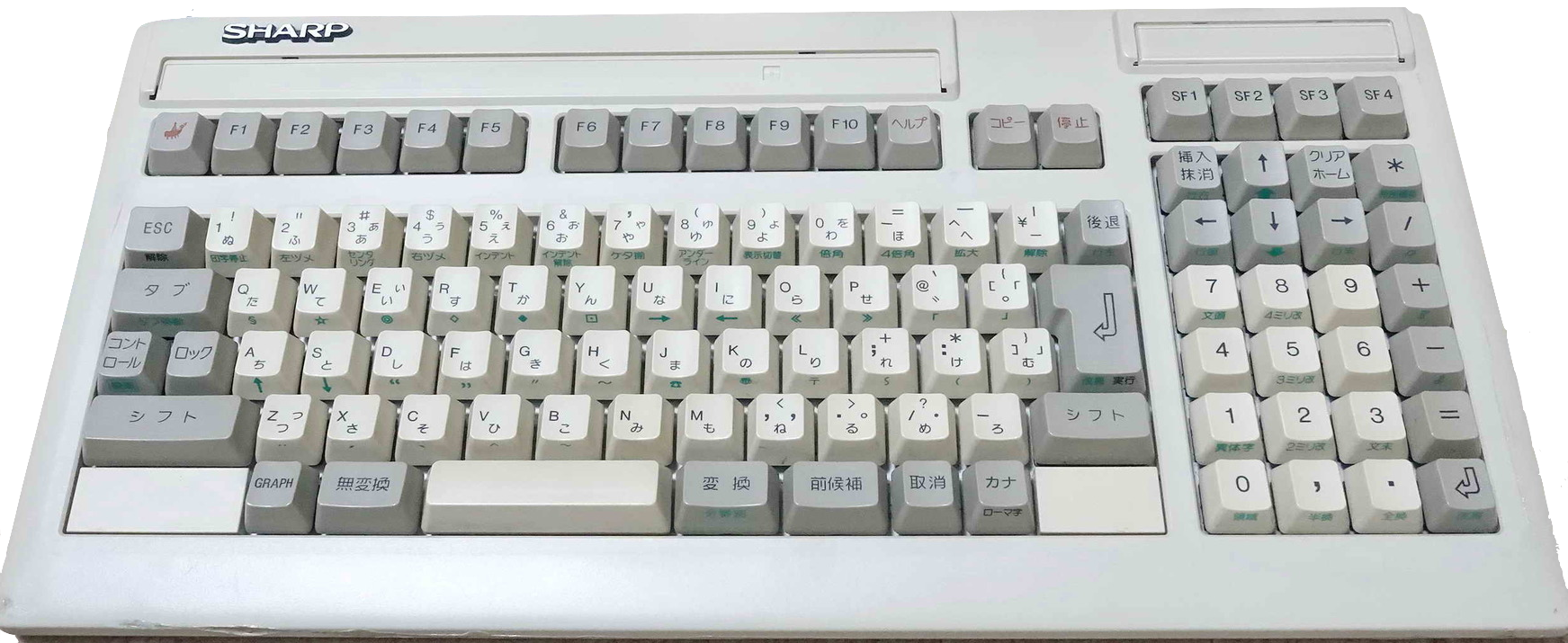 Original Sharp MZ-2800 keyboard.
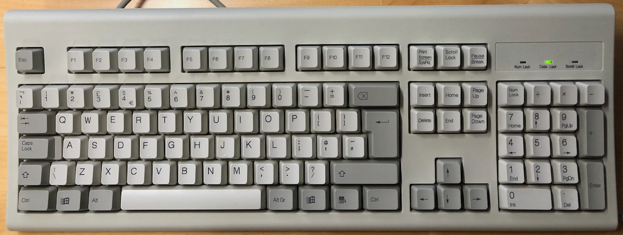 Wyse KB-3926 PS/2 keyboard.
Mapping Table
| MZ-2500 Key | MZ-2800 Key | PS/2 Key | Description | PS/2 Keyboard |
|---|---|---|---|---|
| LOCK | LOCK* | Caps Lock | Shifts and locks upper/lower case characters. Press once to lock upper case, LED light comes on, press again to release and return to lower case characters. | Wyse KB-3926 |
| HELP | HELP* | F11 | HELP functionality | |
| BREAK | BREAK* | Pause | BREAK key. PS/2 normally use CTRL+BREAK to generate a BREAK but the MZ-2500 requires SHIFT+BREAK which doesnt yield BREAK, thus a mapping is created for SHIFT+PAUSE (which is also the same key as BREAK) to create an MZ-2500 BREAK. | |
| COPY | COPY* | F12 | COPY functionality | |
| CLR | CLR* | Shift+Home | Clear screen | |
| HOME | HOME* | Home | Set cursor to 0,0 position ie. HOME. | |
| INST | INST* | Insert | Insert characters at cursor position. | |
| DEL | DEL* | Delete | Delete characters from cursor position. | |
| ARGO | ARGO | Print Screen | ARGO functionality. ie. Bring up applets menu in BASIC v2 | |
| GRAPH | GRAPH | Left GUI | Change to Graphics character entry. | |
| Yen | Yen | |\ | Insert a Yen symbol | |
| KANA | KANA | Right GUI | Select KANA functionality. | |
| KJ1 Sentence | KJ1 Sentence | Left ALT | KJ1 functionality | |
| KJ2 Transform | KJ2 Transform | Right ALT | KJ2 functionality | |
| PREVIOUS* | PGDN | Previous Key | ||
| CANCEL* | Right CTRL | Cancel Key | ||
| SF1 | Special Function 1 | Not yet mapped | ||
| SF2 | Special Function 2 | Not yet mapped | ||
| SF3 | Special Function 3 | Not yet mapped | ||
| SF4 | Special Function 4 | Not yet mapped |
* = Written in Japanese on the MZ-2800.
All other keys are as per the symbol on the PS/2 keyboard. The Num Lock key toggles the keypad between numeric and cursor functions. The keyboard mapping passes through modifier keys unless there is an exact map, ie. SHIFT. Thus key combinations not catered for in the ESP32-S mapping table may work, ie. SHIFT+KANA.
The MZ-2500 can emulate the MZ-2000 and MZ-80B and each machine has slightly different mappings. I’m not sure how the MZ-2500 keyboard got around this as there is no obvious communications protocols sent from the main unit to the keyboard so I’m guessing the gate array on the main unit performs in-situ mapping according to the model mode switch. To cater for this I have placed machine model as a component of the mapping table, normally a key is assigned to all models but when a difference occurs, the difference is tagged to the model accordingly. In order to invoke this functionality it is necessary to press a key combination according to the machine whose mapping you wish to use, listed in the table below.
| Hot Key | Mode |
|---|---|
| ALT+F1 | MZ-2500 Keyboard mapping |
| ALT+F2 | MZ-2000 Keyboard mapping |
| ALT+F3 | MZ-80B Keyboard mapping |
On power up, the default mapping is set to MZ-2500.
The PS/2 keyboard can be connected/disconnected from the interface whilst the MZ-2500/MZ-2800 is powered up, likewise the interface from the MZ-2500/MZ-2800. The reservoir capacitors on the AMS1117-3.3 are larger than needed to cater for sudden power drops as the keyboard is plugged in. The software checks every second for the presence of a keyboard and should it be unplugged, performs a re-initialisation and check in anticipation of the keyboard being plugged back in.
WiFi
Access Point mode allows a user to connect to the interface as a client, invoke a web browser and setup the credentials to allow the interface to connect to a local WiFi router (ie. local net).
Once configured, enabling WiFi mode will automatically join with the configured local Wifi network and present a browser interface for key map configuration.
Pricing
The PCB boards can be ordered up from any PCB Fab such as pcbway and will cost typically about USD5+USD20 P&P for 10. Ordering 1-10 is the same price, so better to take 10.
MZ-2500 Interface
| Part | References | Quantity | Value | Price Each | Price Net | Price Total |
|---|---|---|---|---|---|---|
| 1 | C1, C2 | 2 | 100uF | £0.44 | £0.89 | £0.89 |
| 2 | C3, C4 | 2 | 100nF | £0.06 | £0.11 | £0.11 |
| 3 | R1, R2, R3, R4, R5, R6, R7, R12, R13 | 9 | 100R | £0.02 | £0.18 | £0.18 |
| 4 | R10, R11, R14, R15, R16, R18, R19 | 7 | 10K | £0.02 | £0.14 | £0.14 |
| 5 | R8, R9 | 2 | 2K | £0.02 | £0.04 | £0.04 |
| 6 | R17 | 1 | 1K | £0.02 | £0.02 | £0.02 |
| 7 | D1, D2 | 2 | 1N4001 | £0.26 | £0.53 | £0.53 |
| 8 | D3 | 1 | Power | £0.20 | £0.20 | £0.20 |
| 9 | U1 | 1 | AMS1117-3.3 | £0.33 | £0.33 | £0.33 |
| 10 | U2 | 1 | 74LS257 | £1.00 | £1.00 | £1.00 |
| 11 | U3 | 1 | ESP32-S AI Thinker | £2.08 | £2.08 | £2.08 |
| 12 | F1 | 1 | 500mA | £0.99 | £0.99 | £0.99 |
| 13 | SW1 | 1 | WiFi EN | £0.09 | £0.09 | £0.09 |
| 14 | JP1 | 1 | PGM | £0.00 | £0.00 | |
| 15 | JP2 | 1 | ~{RESET} | £0.00 | £0.00 | |
| 16 | LG1 | 1 | Argo Logo | £0.00 | £0.00 | |
| 17 | Q1 | 1 | MMDT3904 | £0.43 | £0.43 | £0.43 |
| 18 | J1 | 1 | MZ2500 Keyboard | £0.03 | £0.26 | £0.26 |
| 19 | J2 | 1 | PS/2 Keyboard | £1.33 | £1.33 | £1.33 |
| 20 | J3 | 1 | PGM/OLED | £0.03 | £0.23 | £0.23 |
| 21 | 9 pin 2.0mm DuPont Housing | 1 | 9pin DuPont | £1.32 | £0.33 | £0.33 |
| 22 | PCB | 1 | PCB | £2.60 | £2.60 | £2.60 |
| 23 | Case KM24 | 1 | KM24 | £2.35 | £2.35 | £2.35 |
| 24 | Prefab 8pin mini-din wire | 1 | MZ-2500 Connector | £5.83 | £5.83 | £5.83 |
| Total | £19.96 | £19.96 |
MZ-2800 Interface
| Part | References | Quantity | Value | Price Each | Price Net | Price Total |
|---|---|---|---|---|---|---|
| 1 | C1, C2 | 2 | 100uF | £0.44 | £0.89 | £0.89 |
| 2 | C3, C4 | 2 | 100nF | £0.06 | £0.11 | £0.11 |
| 3 | R1, R2, R3, R4, R5, R6, R7, R12, R13 | 9 | 100R | £0.02 | £0.18 | £0.18 |
| 4 | R10, R11, R14, R15, R16, R18, R19 | 7 | 10K | £0.02 | £0.14 | £0.14 |
| 5 | R8, R9 | 2 | 2K | £0.02 | £0.04 | £0.04 |
| 6 | R17 | 1 | 1K | £0.02 | £0.02 | £0.02 |
| 7 | D1, D2 | 2 | 1N4001 | £0.26 | £0.53 | £0.53 |
| 8 | D3 | 1 | Power | £0.20 | £0.20 | £0.20 |
| 9 | U1 | 1 | AMS1117-3.3 | £0.33 | £0.33 | £0.33 |
| 10 | U2 | 1 | 74LS257 | £1.00 | £1.00 | £1.00 |
| 11 | U3 | 1 | ESP32-S AI Thinker | £2.08 | £2.08 | £2.08 |
| 12 | F1 | 1 | 500mA | £0.99 | £0.99 | £0.99 |
| 13 | SW1 | 1 | WiFi EN | £0.09 | £0.09 | £0.09 |
| 14 | JP1 | 1 | PGM | £0.00 | £0.00 | |
| 15 | JP2 | 1 | ~{RESET} | £0.00 | £0.00 | |
| 16 | LG1 | 1 | Argo Logo | £0.00 | £0.00 | |
| 17 | Q1 | 1 | MMDT3904 | £0.43 | £0.43 | £0.43 |
| 18 | J1 | 1 | MZ2500 Keyboard | £0.03 | £0.26 | £0.26 |
| 19 | J2 | 1 | PS/2 Keyboard | £1.33 | £1.33 | £1.33 |
| 20 | J3 | 1 | PGM/OLED | £0.03 | £0.23 | £0.23 |
| 21 | 9 pin 2.0mm DuPont Housing | 1 | 9pin DuPont | £1.32 | £0.33 | £0.33 |
| 22 | PCB | 1 | PCB | £2.60 | £2.60 | £2.60 |
| 23 | Case KM24 | 1 | KM24 | £2.35 | £2.35 | £2.35 |
| 24 | Host side Plug | 1 | 3M 10120-6000EL Plug | £3.90 | £3.90 | £3.90 |
| 25 | Host side plug hood | 1 | 3M 10320-3210-000 Hood | £5.14 | £5.14 | £5.14 |
| 26 | Main unit Replacement Socket | 1 | 3M 10220-5212PL Socket | £3.86 | £3.86 | £3.86 |
| 27 | Main unit replacement 9pin header and socket | 1 | JST XH2.50mm 9 way | $2.68 | £2.68 | £2.68 |
| Total | £29.71 | £29.71 |
Credits
Licenses
No commercial use to be made of this design or any hardware/firmware component without express permission from the author. This condition overrides any rights afforded by the GNU GPL 3 license.
The Gnu Public License v3
The source files are distributed in the hope that it will be useful, but WITHOUT ANY WARRANTY; without even the implied warranty of MERCHANTABILITY or FITNESS FOR A PARTICULAR PURPOSE. See the GNU General Public License for more details.
You should have received a copy of the GNU General Public License along with this program. If not, see http://www.gnu.org/licenses/.