 Sharp MZ-2000 Renovation
Renovation
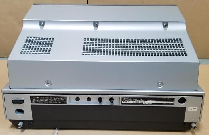
The machines arrived and apart from one, the machines were filthy, no doubt stored in a loft or warehouse for the last 30 years. I powered each one up and was pleasantly suprised when the 'Make CMT Ready' was displayed on all three machines. That is where the luck ran out, all 3 cassette drives didnt work and placing a tape into one of them jammed immediately with a strange oil like substance on the tape. When the tape jams, the only way to unjam it is to take off the back monitor panel and manually turn the tape flywheel, a previous owner, on one of the machines, decided trying to use a screwdriver on the cassette door was the right approach!!! On investigation, the black oil like substance was the pinch roller, it had turned into a black gunge on all 3 machines!
I'm writing this information after renovating two of the three machines and besides the tape deck requiring major work one of the machines monitor failed, the vertical scan collapsed into a single vertical line. The third machine I am yet to work on or use.
In addition to renovation I want to convert one of the machines to UK 240V AC as I intend to develop my Sharp MZ Series emulation and tranZPUter SW-700 on it and for safety best I use the local voltage because development sees you plugging and unplugging the machine and at some point I may make a mistake and plug into the UK mains and not the VARIAC!
Testing on the transformer indicates the primary winding only has one coil and it is limited by design to input voltage. The input current rises exponentially as the voltage goes > 140VAC (tested using a VARIAC) so my new solution will be the replacement of the original laminated core transformer with a toroid. The toroid I've chosen has 2x22VAC@2Amp + 15-0-15VAC@1Amp outputs and 2x115VAC primary input coils, 3 of the output coils are required by the MZ-2000 PSU and I can make the 2x115VAC primary coils run in parallel (115V AC) or series (240V AC) which maintains a modicum of originality. The toroid will sit on a plastic adapter and be held down by the original transformer screws so no damage to the machine will be incurred.
The details below are a work in progress, I will add more photos and detail over time.
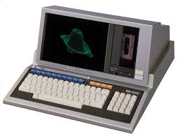
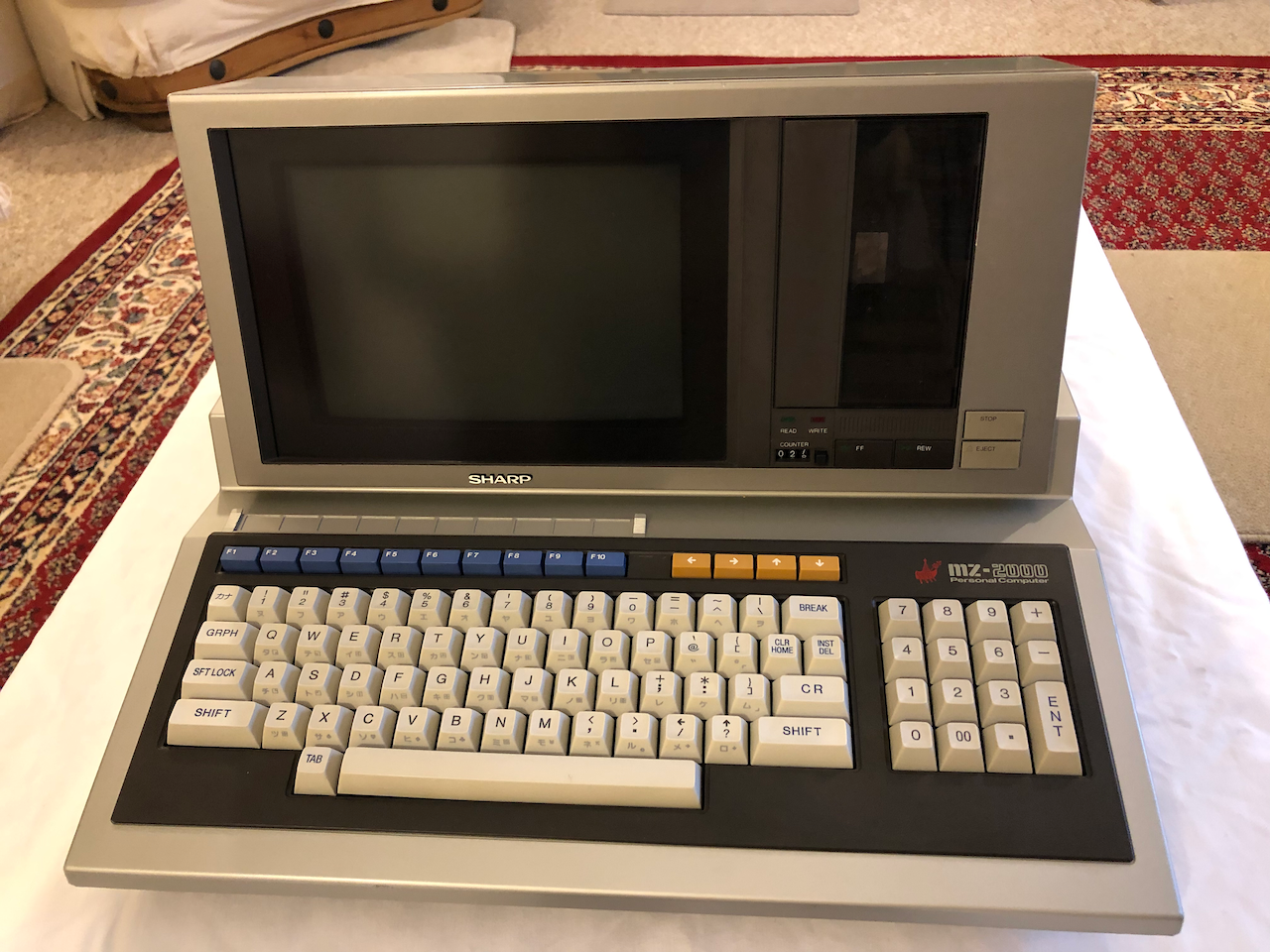
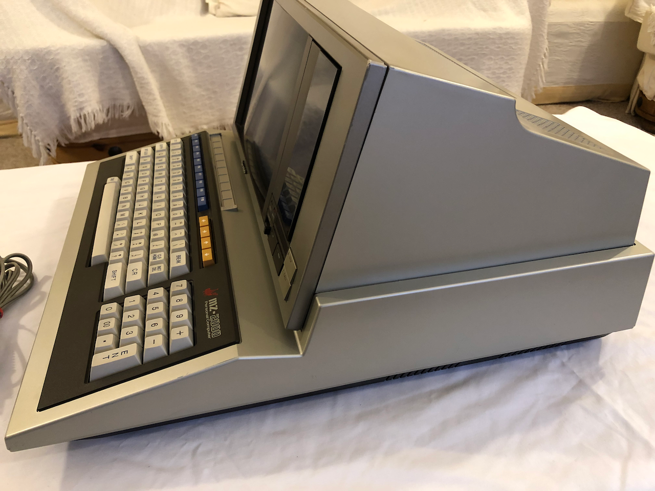
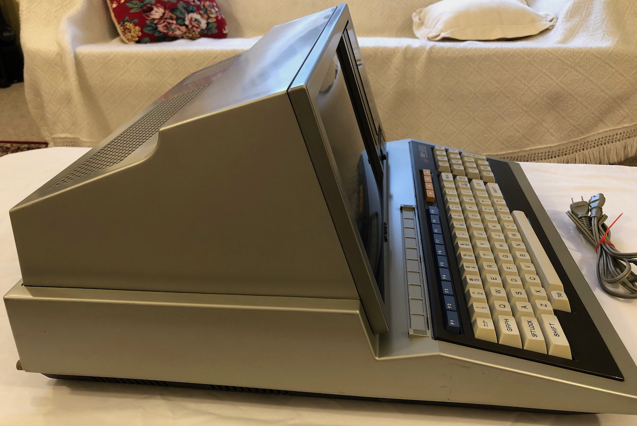
First up, the three machines to be renovated.
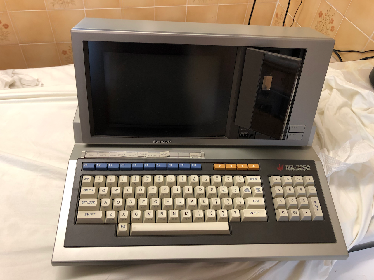
The first machine, visually, needs only to be cleaned.
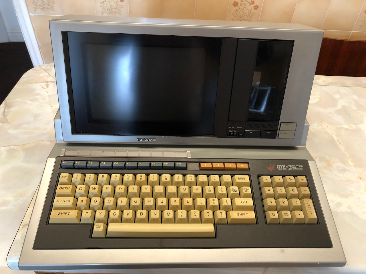
The second machine, visually, requires some attention to the key caps and a good clean.
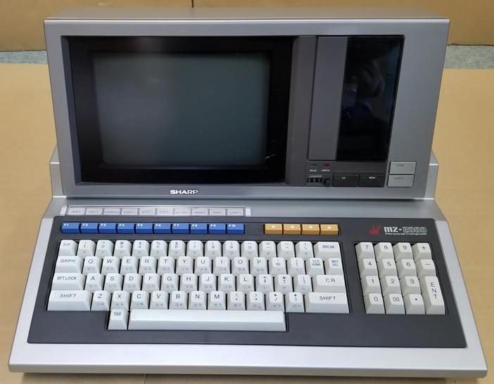
The third machine, the one I havent yet renovated, will take pride of joy next to my MZ-80A once I get around to renovating it and dealing with any gotchas! It powers up ok but after what I’ve learnt so far, all the caps need to be replaced especially in the monitor and that cassette drive, what adventures lurk within it!!!
Strip down
The first step was to strip the machine down to it’s individual components. I didnt take so many photos from the first two machines so will endeavour to enrich the photo’s below from the 3rd when I get around to renovating it. Some of the photos below are actually taken during reassembly, I was too engrossed during disassembly to take them!
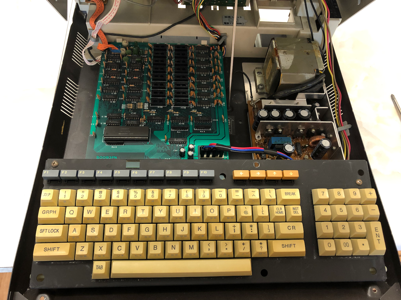
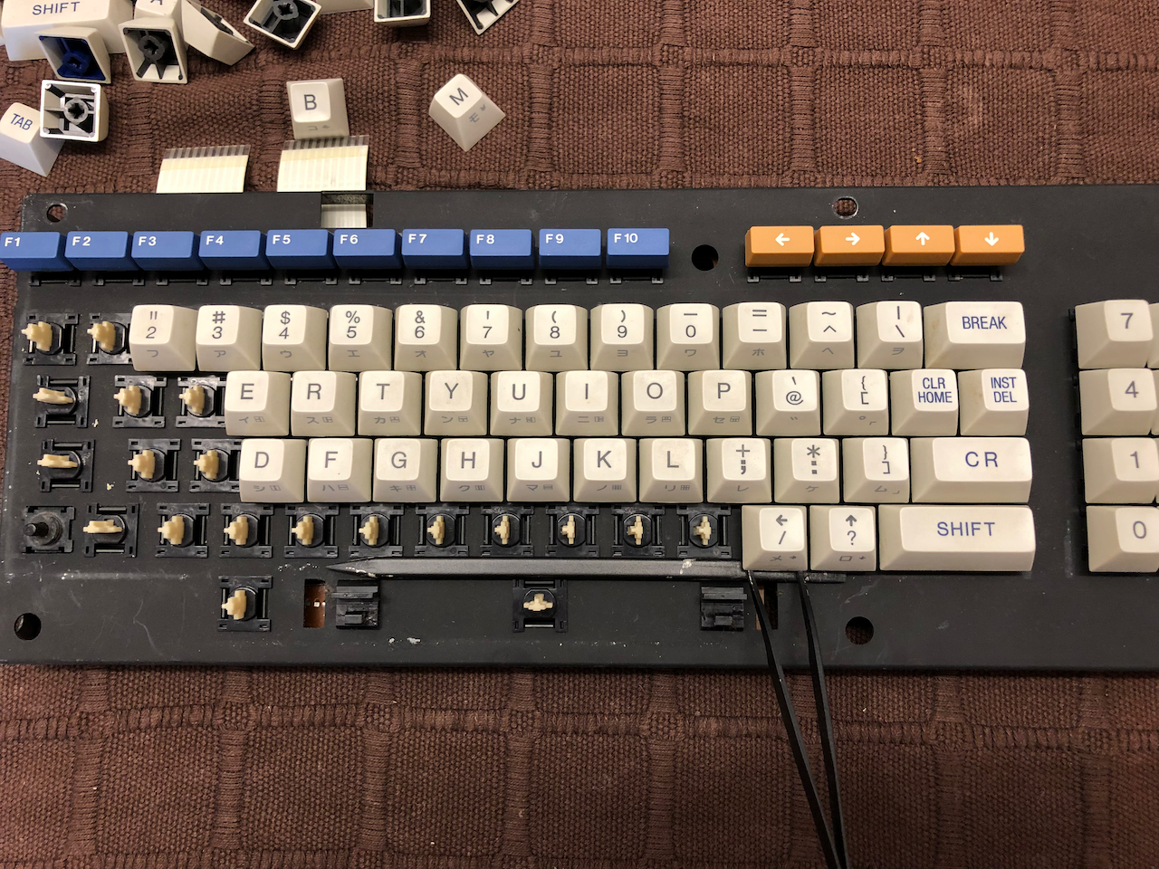
First up, open the casing like an MZ-80A, unscrew the keyboard and remove.
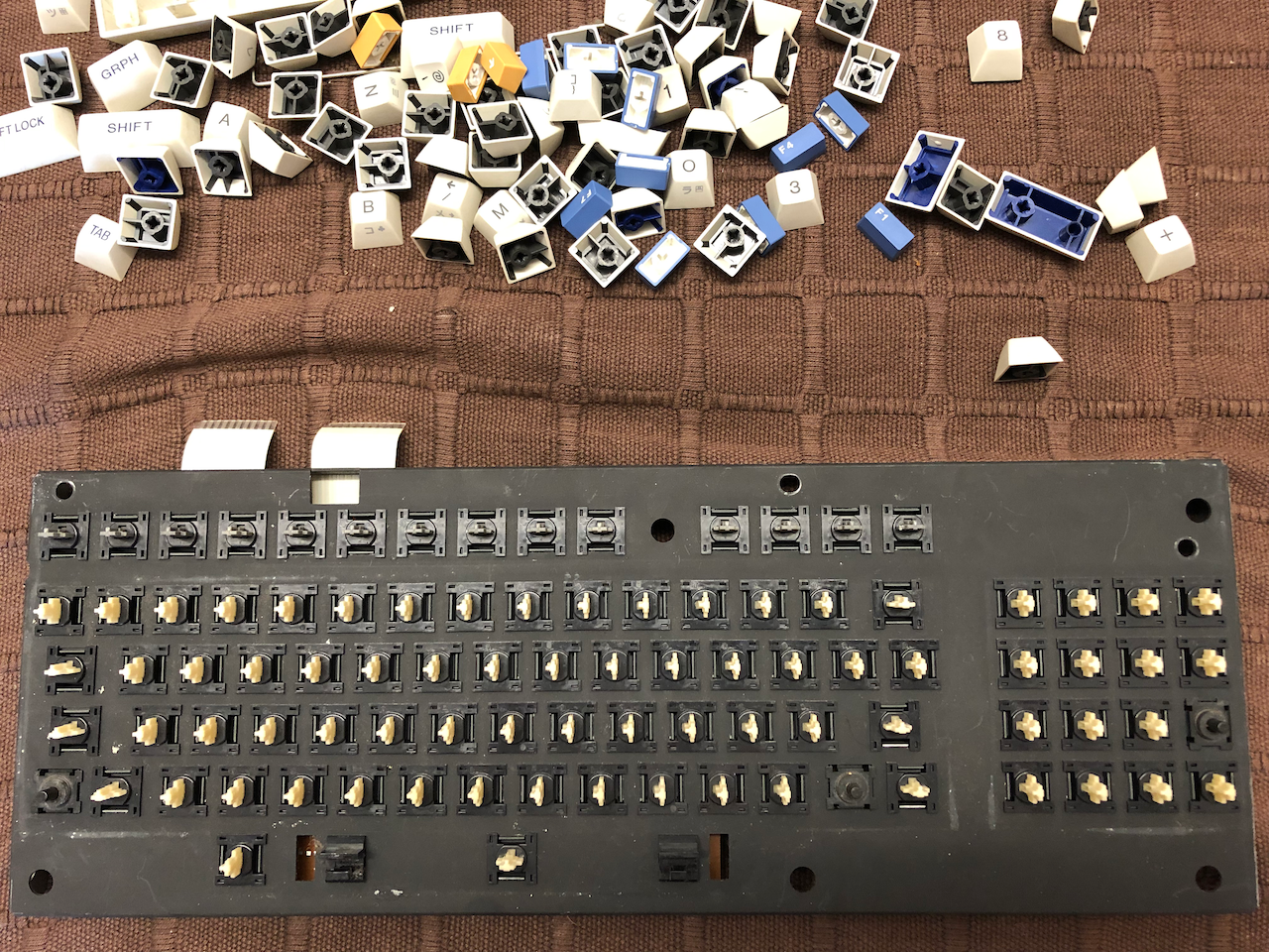
Once the keyboard is removed, all the key caps need to be prised off for cleaning. One method of doing this is to use a thin piece of plastic which just fits under the keys and electronic tweezers which you use to go under the key and apply equal force to push the cap upwards and off. If the force isnt equal you may end up with a broken key plunger.
After key removal, use an air compressor to blow out all the dirt and dust, isopropyl alcohol to clean the circuit board and contacts and then lubricate the keys with contact cleaner by squirting a small amount into each key. Once the contact cleaner is inside the key it is necessary to press the plunger a few times to complete the cleaning. The key caps are now cleaned with warm water and soap or retrobrite if they are heavily yellowed.
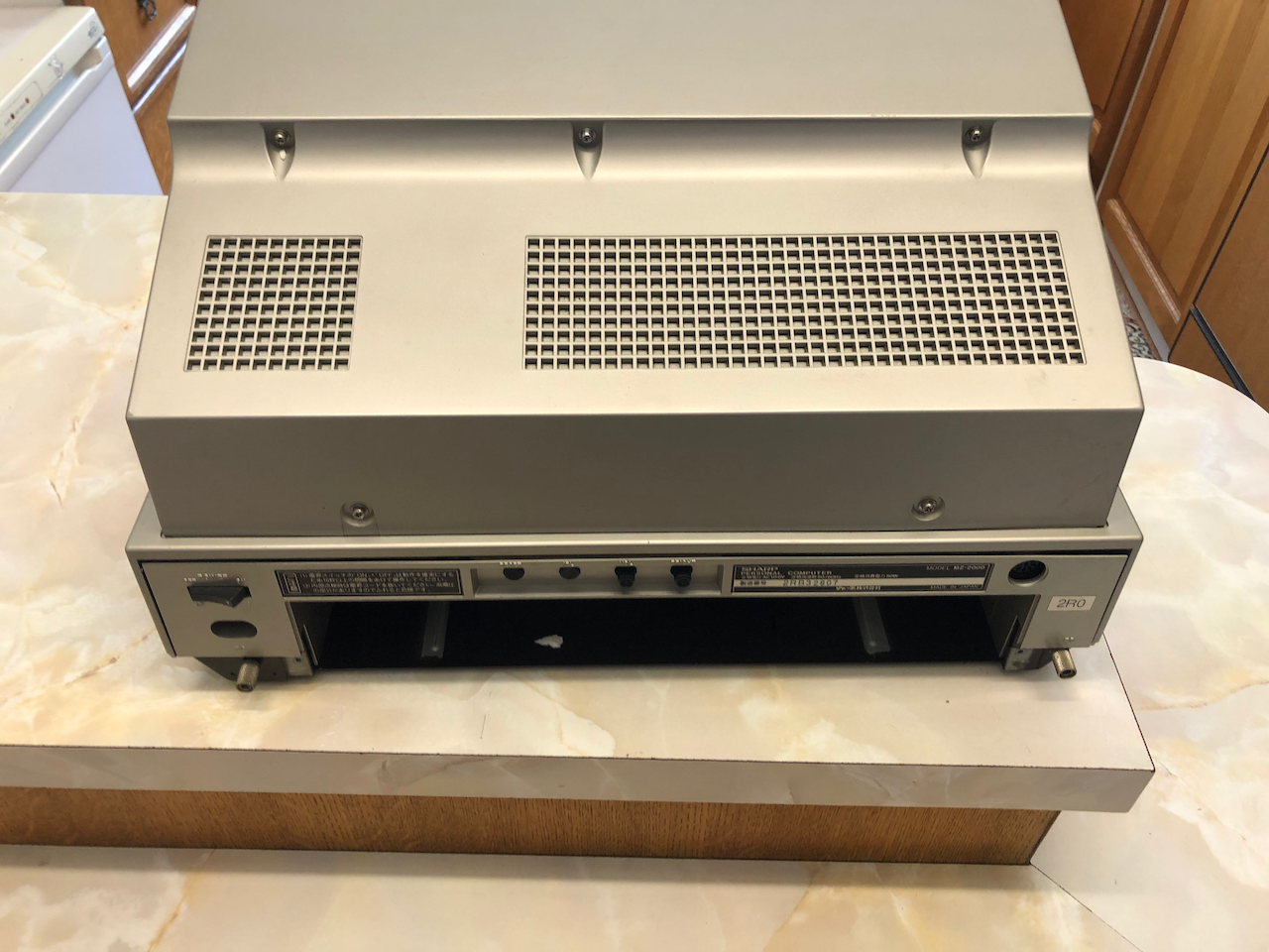
Returning to the main unit, unplug all the power and video connectors from the motherboard and detach the rear volume/brightness/reset/IPL daughter card then close the lid. Remove the monitor cover (5 screws on the rear of the monitor cover) to gain access to the monitor and cassette player.
Remove the 3 screws holding the monitor/cassette framework onto the main body, push forward and lift off the entire monitor/cassette/fascia assembly. Place on something soft and clean.
 G
G
After the monitor/cassette framework has been removed the mounting frame needs to be detached, this is done by removal of the brackets and undoing the hinges, the top casing then lifts off.
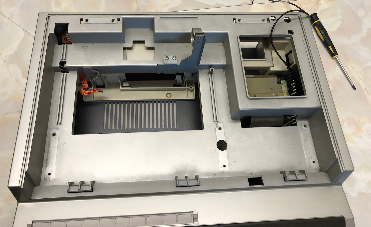
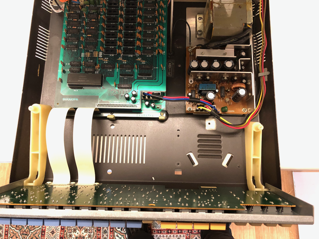
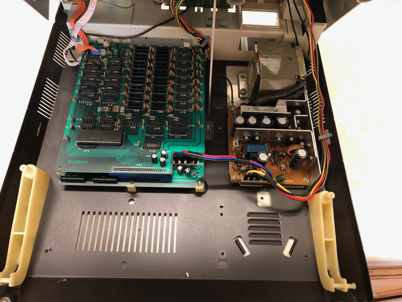
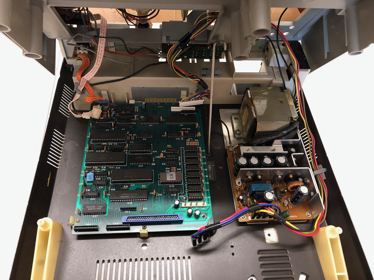
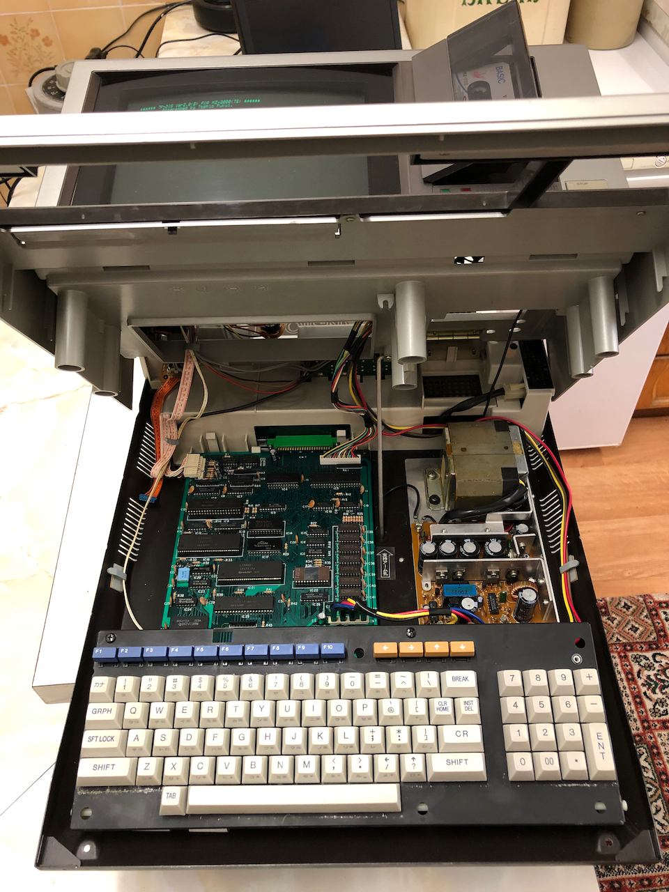
The motherboard is then removed along with the power supply and video connector.
The rear plastic frame is then removed by 2 screws on each of the left/right sides. The metal base cleaned and any exposed metal or rust treated.
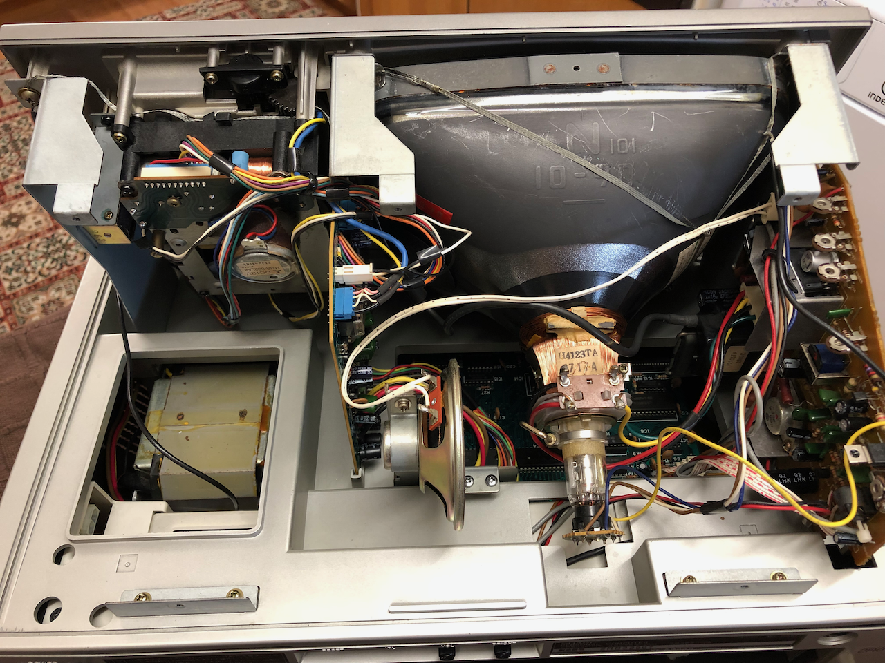
Monitor
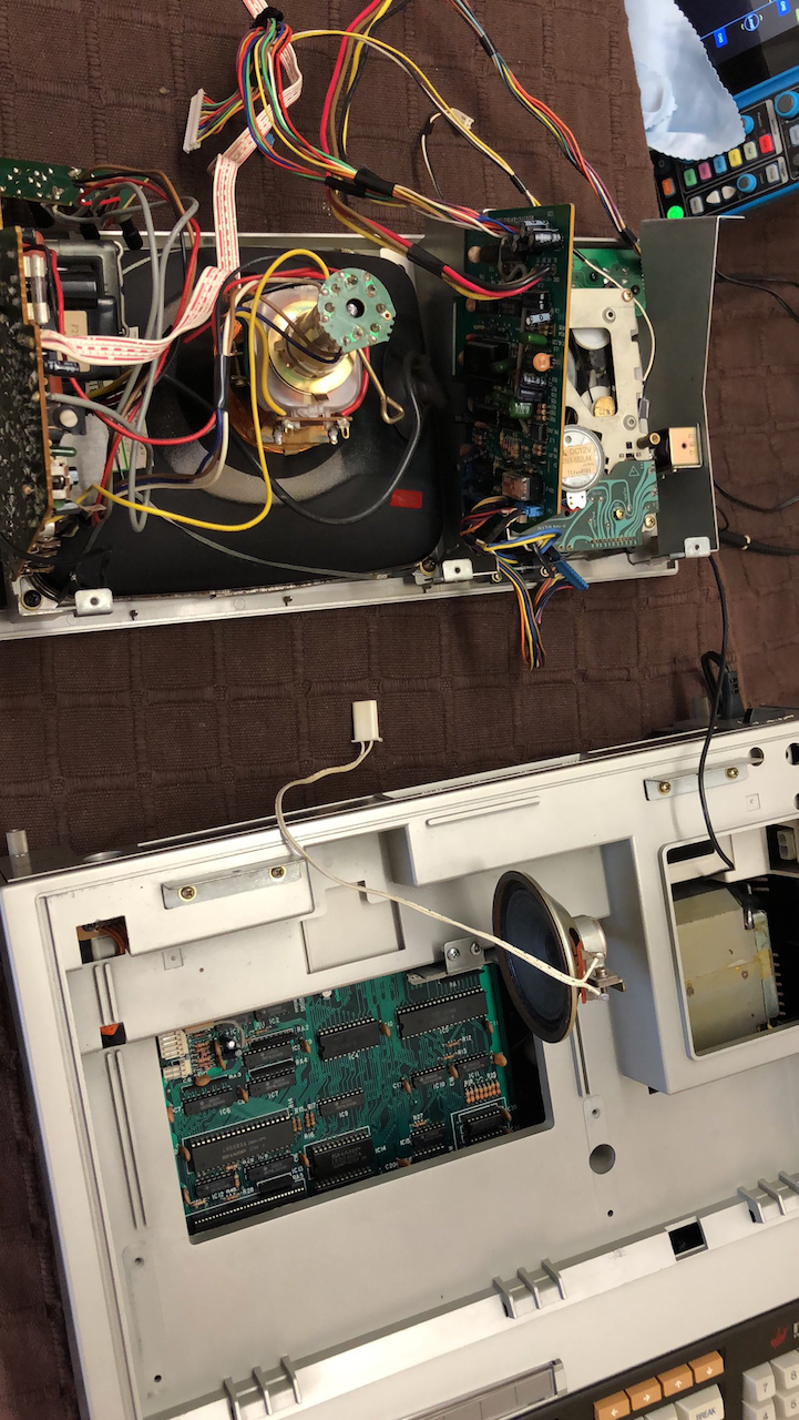
The monitor framework is then disassembled removing the monitor and the cassette drive.
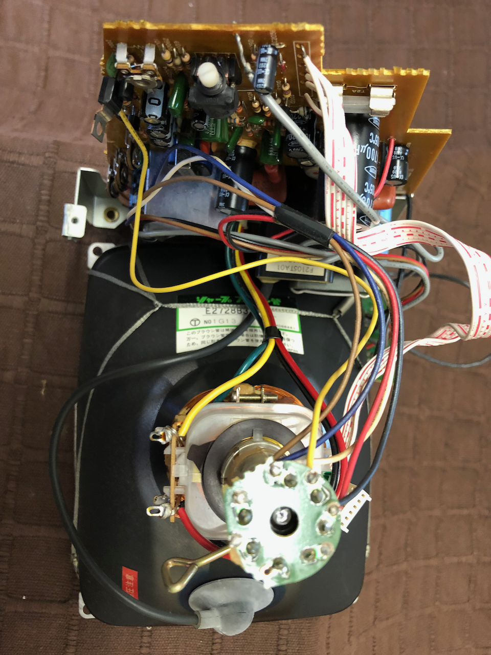
The monitor circuit boards need cleaning and as was the case for 2 failed units and subsequent monitors I’ve worked on, replacing all the capacitors is almost mandatory more especially if gunge can be seen or felt on the circuit board. 40 year old capacitors in a high heat high voltage setting doesnt make for continued reliability. Simplest method to replace them is mark each with a black marker pen and work round the board desoldering old and replacing with new. The schematic and part numbers can be found in the Owners Manual
In respect of the capacitors, the 10uF Bi Polar capacitor is removed and tested only. There is no specification on this part but it needs to be a low ESR and low ripple unit and modern parts are 1/4 the size which if you are to fit will see it popping in an hour!! I was lucky the old unit was in good order as it is not so easy to find a modern equivalent other than assembling a 10uF polyester replacement as suggested on the vintage radio forums.
Of the two failed units, one had a vertical deflection driver IC uPC1031H damaged and another had the capacitor in the RC timebase for the vertical deflector IC open circuit. One note for the vertical deflector IC uPC1031H is that you can only easily get the H2 model now so you have to make a small adaptation to the heatsink as the H2 has a smaller tab than the H version. The deflector IC can be seen in the picture below attached to the heatsink.
Once the capacitors have been replaced, reassemble and test outside of the main unit in order to verify voltages and adjust the monitor. You have the normal Vertical/Horizontal Hold, Linearity, Size, Contrast, Brightness but you may also need to adjust the deflector coil assembly on the yoke and the centering rings.
In the photo below the monitor has been placed into the fascia without the cassette assembly for testing and calibration.
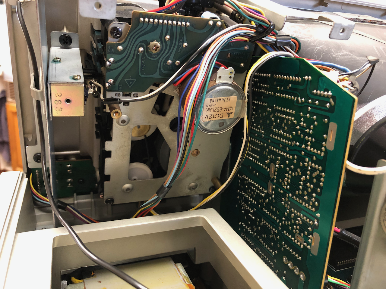
Cassette Drive
Next up is the cassette drive. Having spent many hours with this unit it is very well made, just age has taken it’s toll on the nylon components and the grease has dried and leave its thickeners as a powdery deposit.
Initially the cassette drive is removed from the fascia mounting plate.
Not forgetting to remove the tape counter and pulse detector/key switches.
The board below is for the front cassette switches, remove for inspection and cleaning.
Tape counter, switches and eject solenoid removed. The background is a carpet as I found this the safest way to avoid scratching the monitor/fascia during disassembly and assembly.
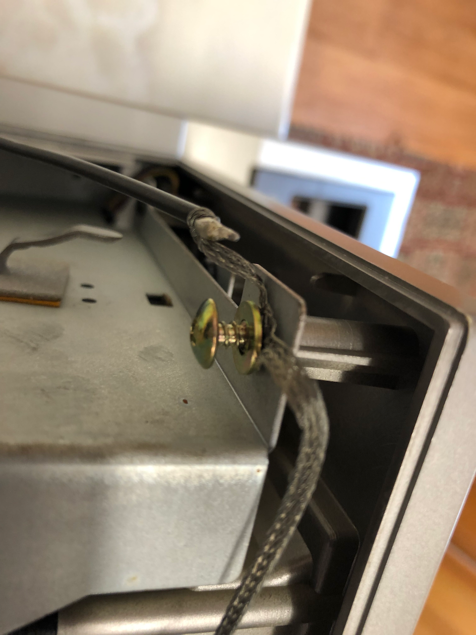
This is important, the Japanese really ensure all metalwork is grounded. a long wire from the frame ground works up to the cassette drive mounting and then across to the monitor frame.
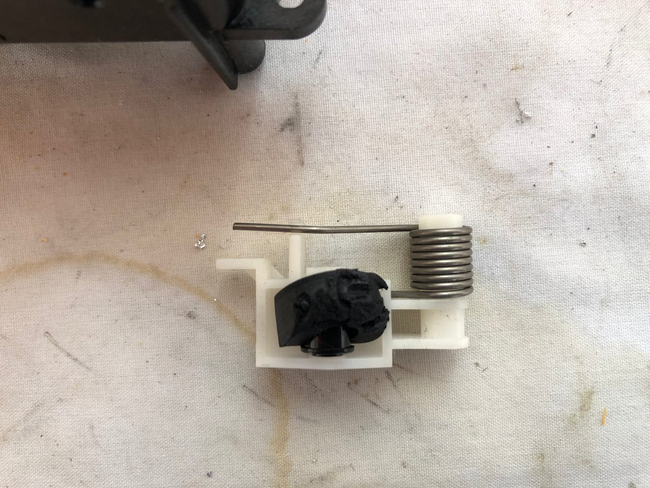
First thing that can be seen is the pinch roller which has disintegrated. All the cassette drives I’ve come across from the MZ-2000/MZ-2500 series have suffered this fate as well as a rubber tape belt in a QD drive!
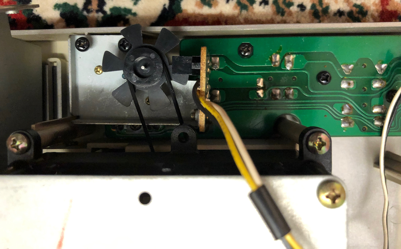
Now for disassebly of the cassette drive itself. Two connectors go between the drive and the control board, unplug both ready for control board seperation.
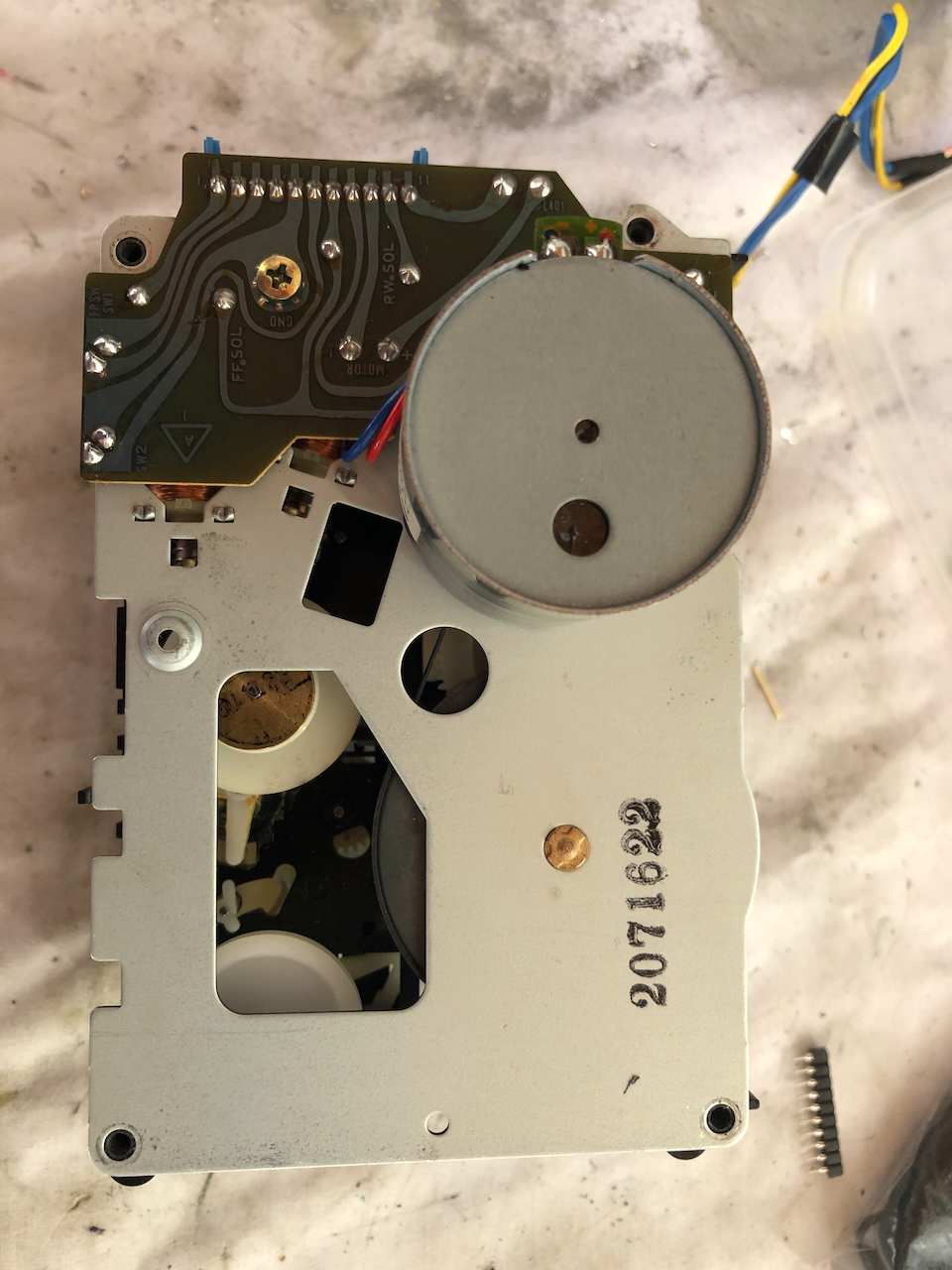
The top motor and plate are removed by 4 corner screws AND you need to de-solder the tape/record detection switches.
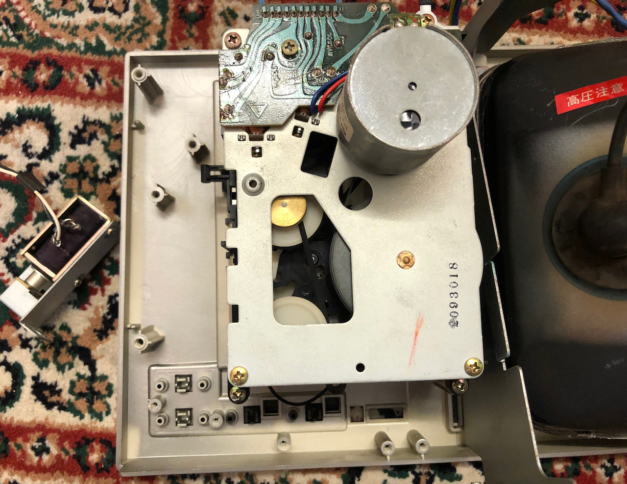
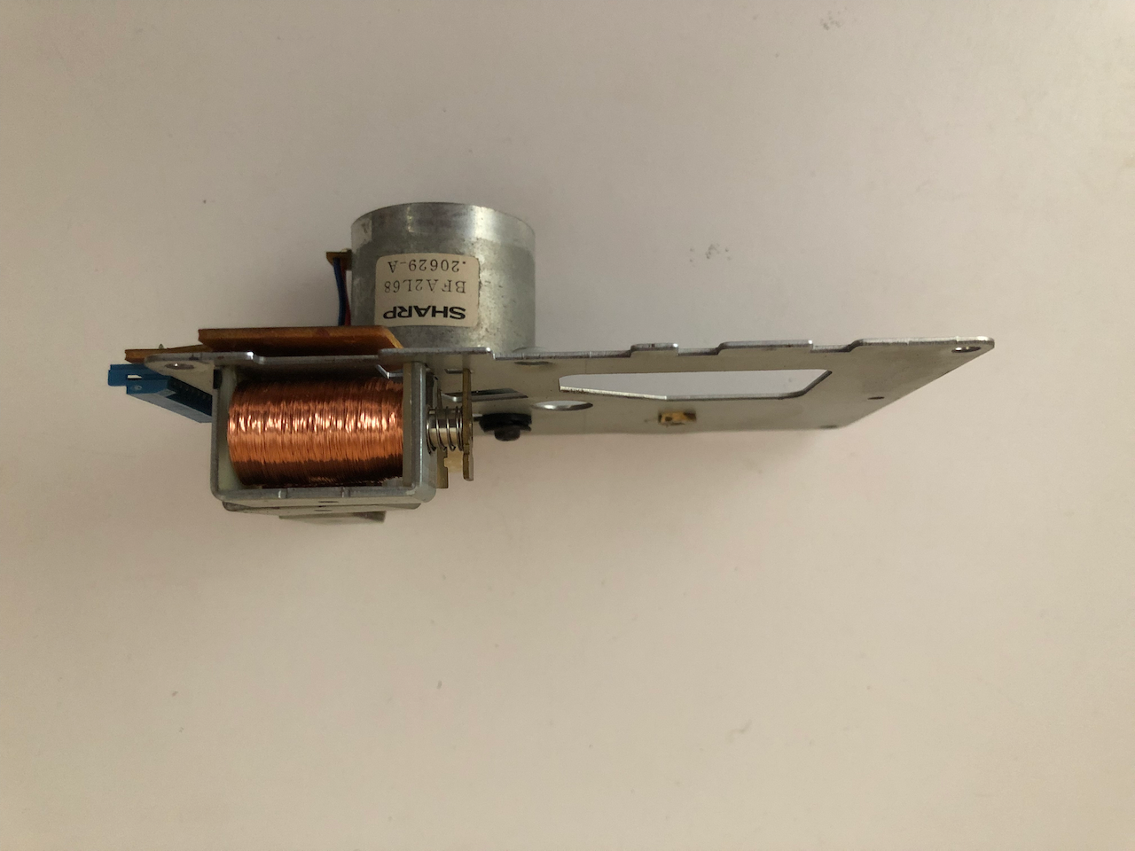
Underside view of the motor plate, 3 solenoids and a rubber mount for the motor.
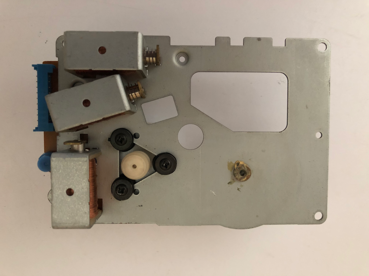
Side on image of the motor plate.
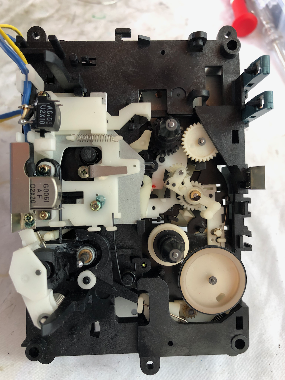
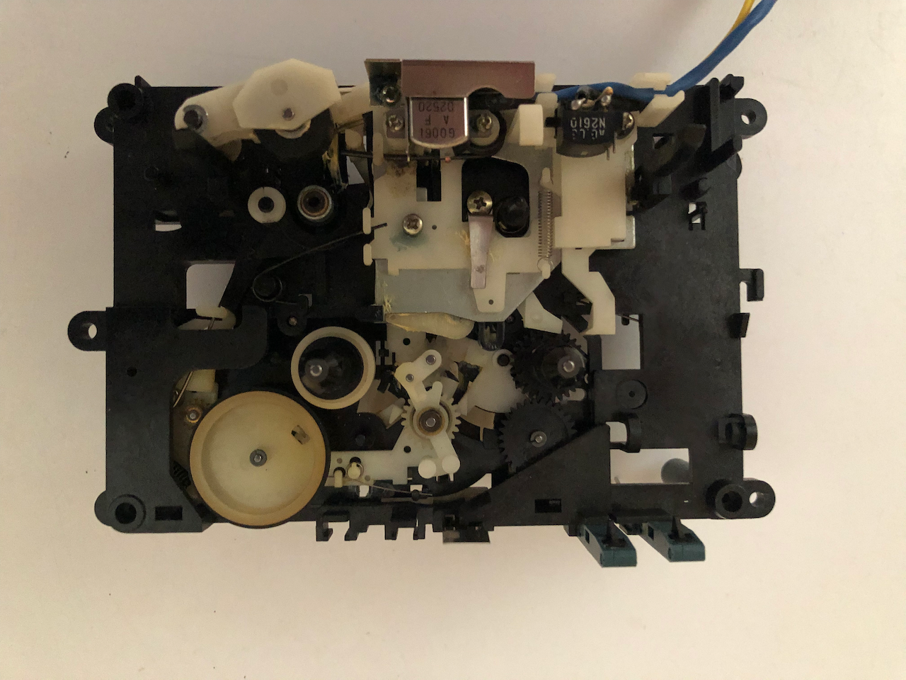
Underneath the motor plate you find the main mechanism - I had removed the drive belts and flywheel before thinking to take a photo!!
Tape side of the mechansim.
Remove the 2 screws fixing the main drive assembly to the rest of the cassette mechanism. This leaves the heads still mounted on there plate.
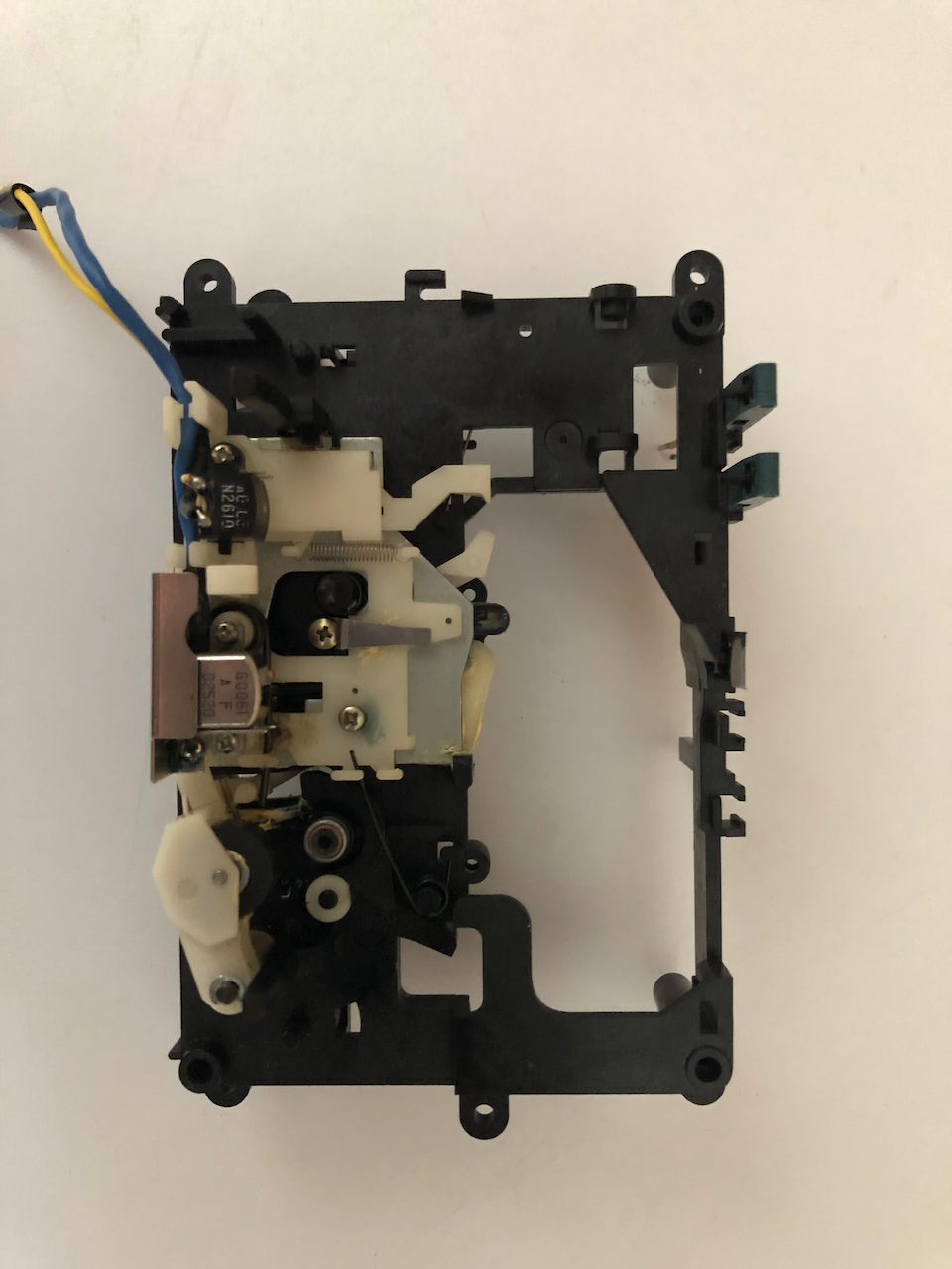
Opposite side showing the cog which engages/retracts the tape heads from the tape.
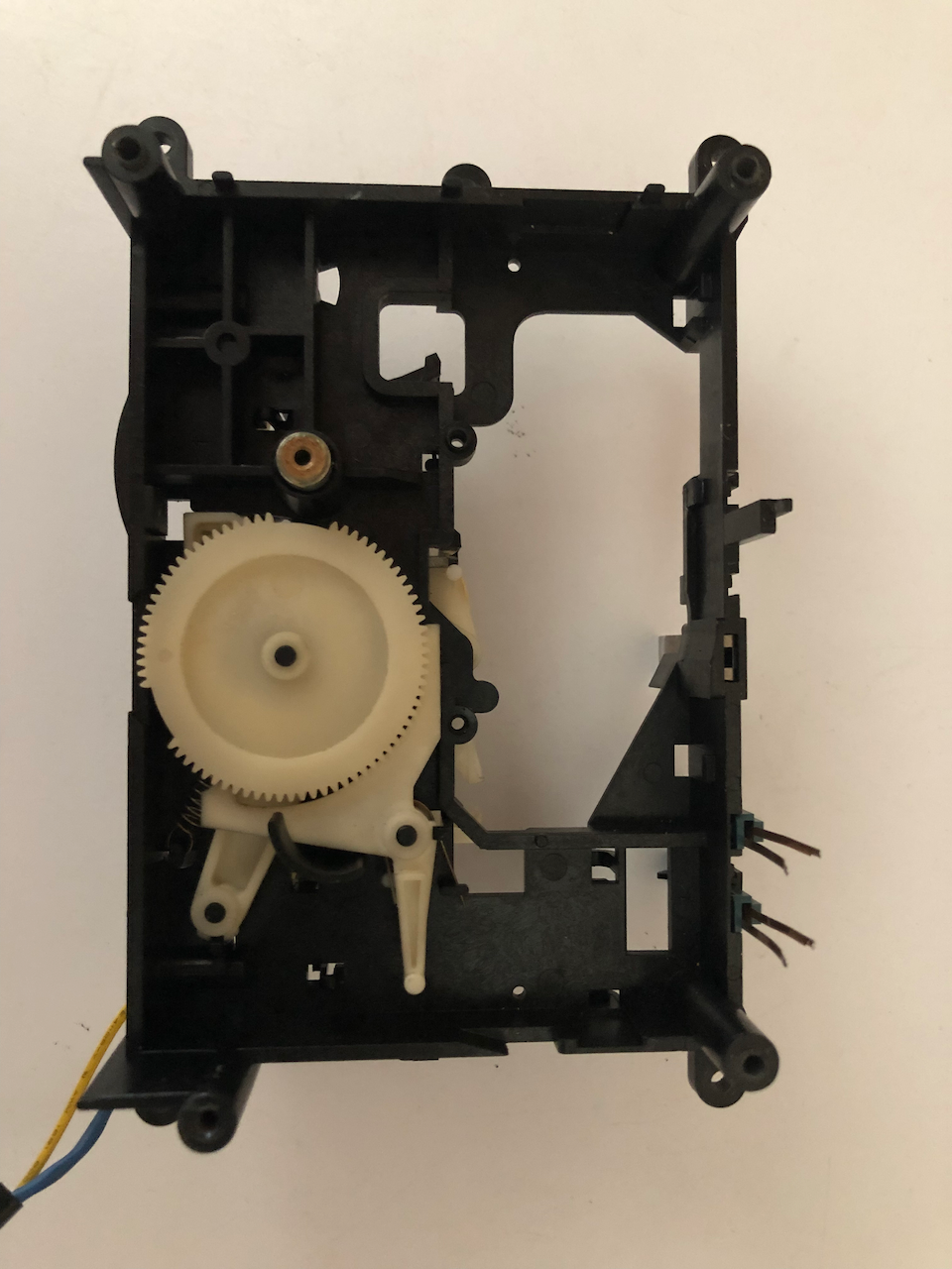
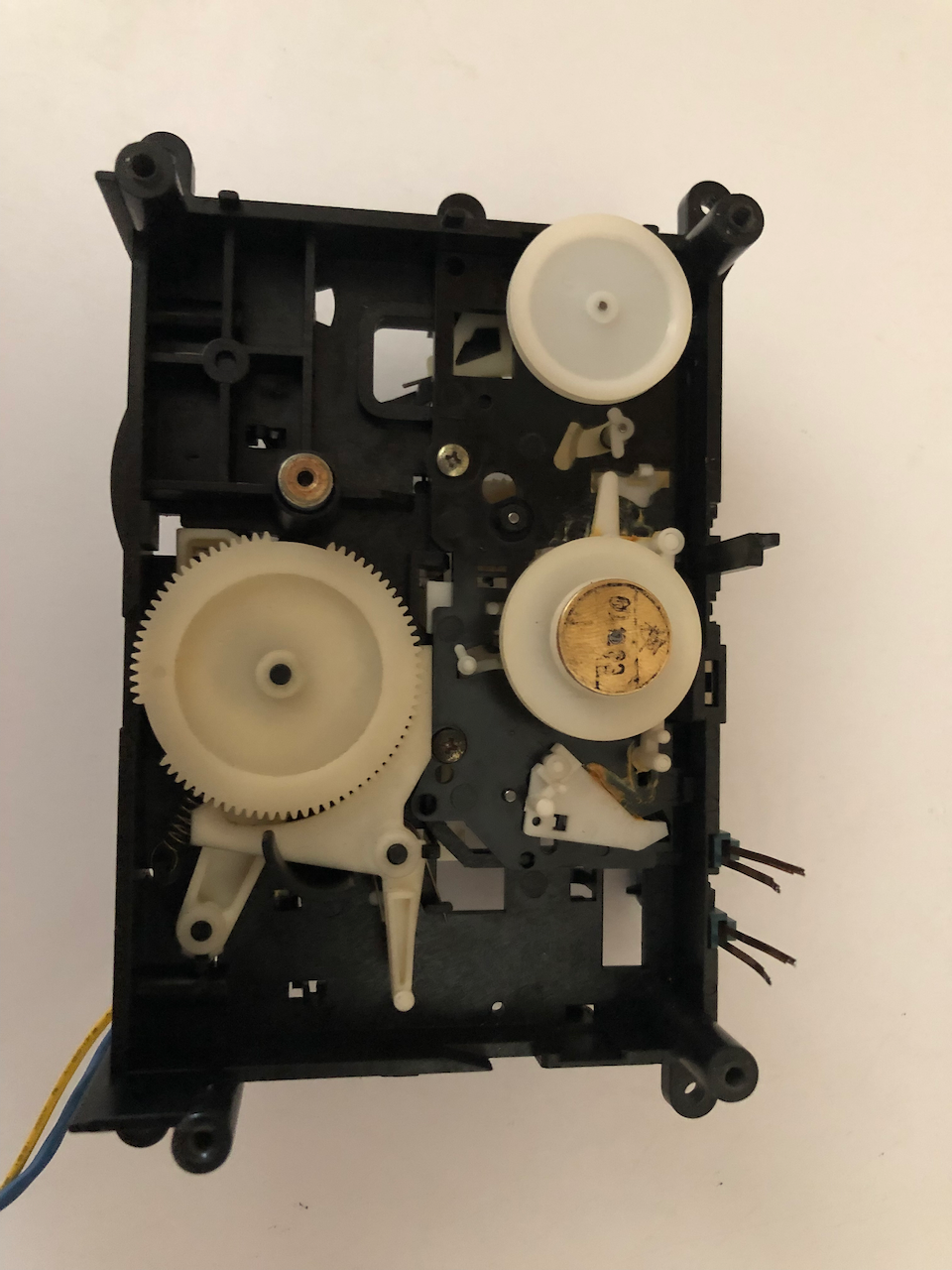
It is here on the main tape assembly where you will likely find the cracked pulleys and cogs. In the center of the photo between the two drive pulleys you can see a
cog with a flying smaller cog which flys around engaging the supply/takeup pulleys according to the solenoid selection. Below this is a cog with a friction clutch, basically a compression
fit nylon cog which has sufficient friction to enagage the pulleys and turn a standard cassette. If the tape jams and the pulleys stop then the friction is overcome and the cog stops spinning
as the spindle rotates inside it. This cog cracks and leads to Rewind/Fast Forward failures.
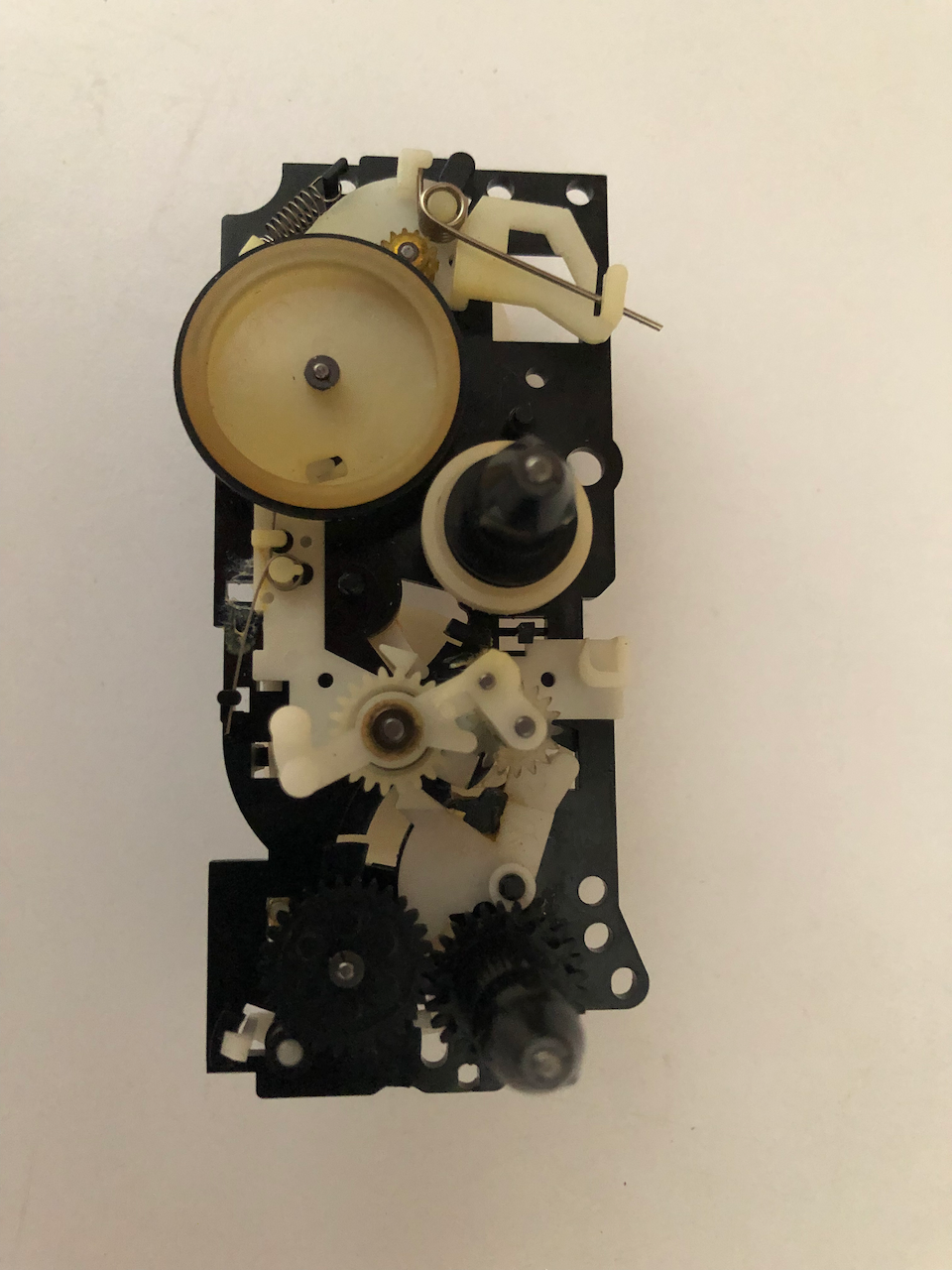
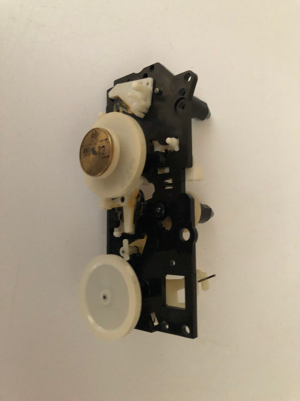
Opposite side of the clutch cog, the pulley with the gold top, this is turned by the motor with the spindle going through to the tape side and the clutch cog.
I tried using plastic cement to fix the clutch cog crack but it doesnt work. The only solutions I can think of would be to use a 2mm external circlip clamped around the cog shaft or to get the parts 3d scanned and printed. In order to scan and print, ideally, you need undamaged parts and you also need a pulley puller to seperate the cogs (which I dont have and still trying to buy one).
Once the cracked cogs have been fixed you need to clean and grease every friction point, failure to do this will lead to jams such as the heads partially engaged.
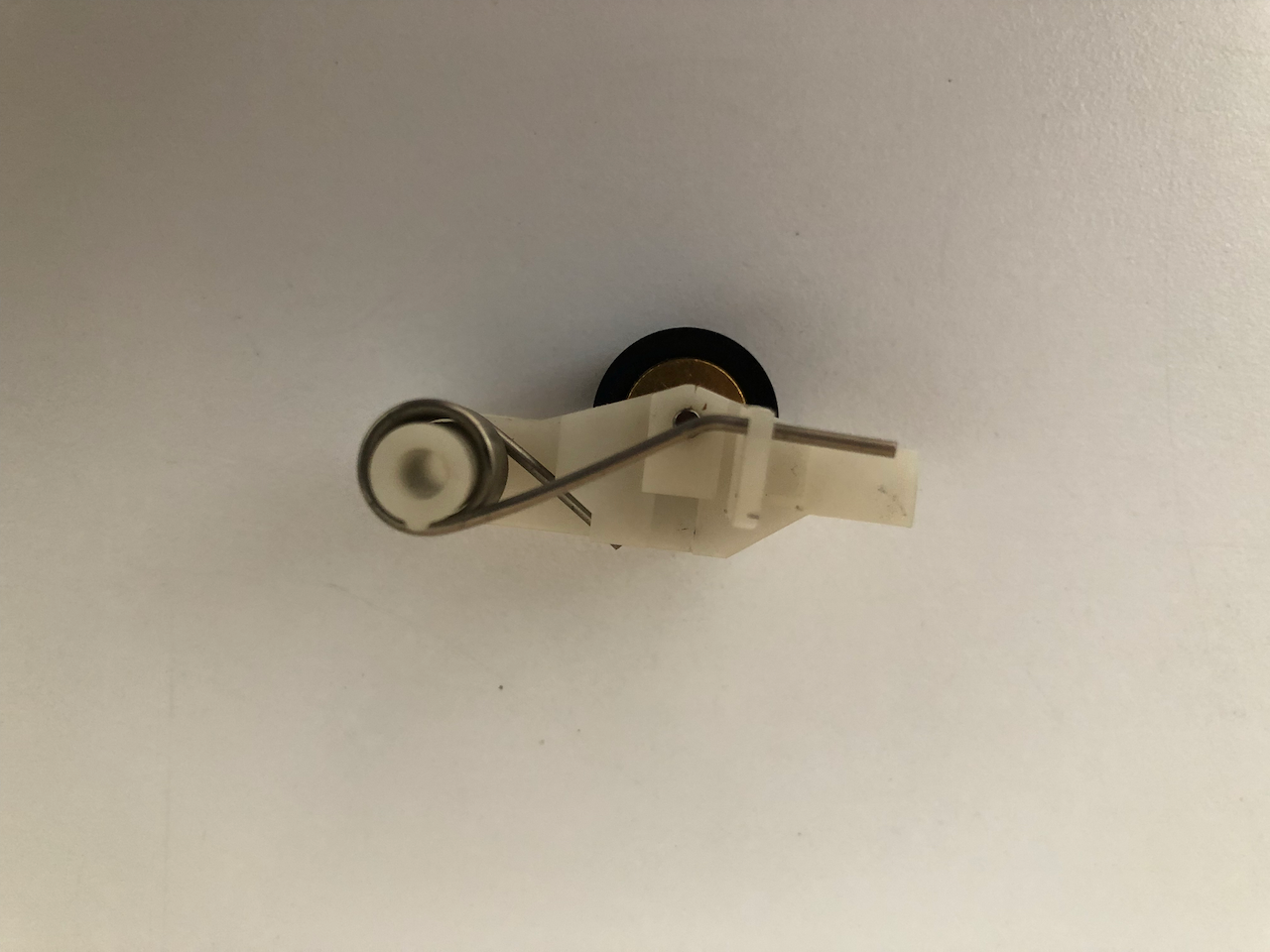
Another major failure point of this mechansim as illustrated above is the pinch roller, which turns to mush! Luckily you can still buy them from China, a 13x8mm with 2mm spindle diameter and 6mm rubber height.
A new pinch roller already mounted.
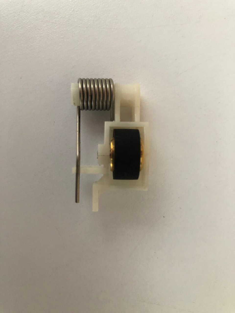
Side on of the pinch roller.
After fixing all the problems, reassemble with new unkinked drive belts (the old ones take on a kink and this leads to issues with the heads being engaged/retracted. I dont have exact sizes, I use the old one as a template and find a belt in my assortment which is just a few mm in diameter shorter. Also dont forget to resolder
After reassembly, mount the cassette mechanism onto the machine fascia, along with the switches, eject solenoid, tape counter and tape counter drive belt. One note, if the azimuth is out you will need to remove the cassette fascia tape drawer in order to adjust it. This is because you cannot run the drive without the tape counter attached and as this is a seperate unit all the cassette mechanism is needed to be mounted.
This is how it looks when the cassette drawer is removed for access to the head screws to adjust the azimuth.
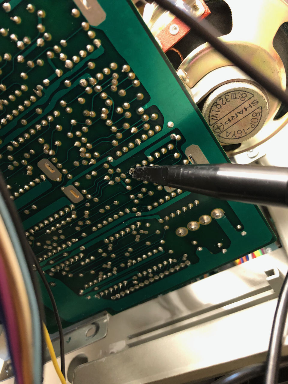
Use a calibrated alignment cassette, I used a 3KHz alignment cassette and connect your scope to pin 7 of the LM324 IC, the output is a frequency modulated representation of the data/signal, just adjust the azimuth to get the best amplitude.
Power Supply
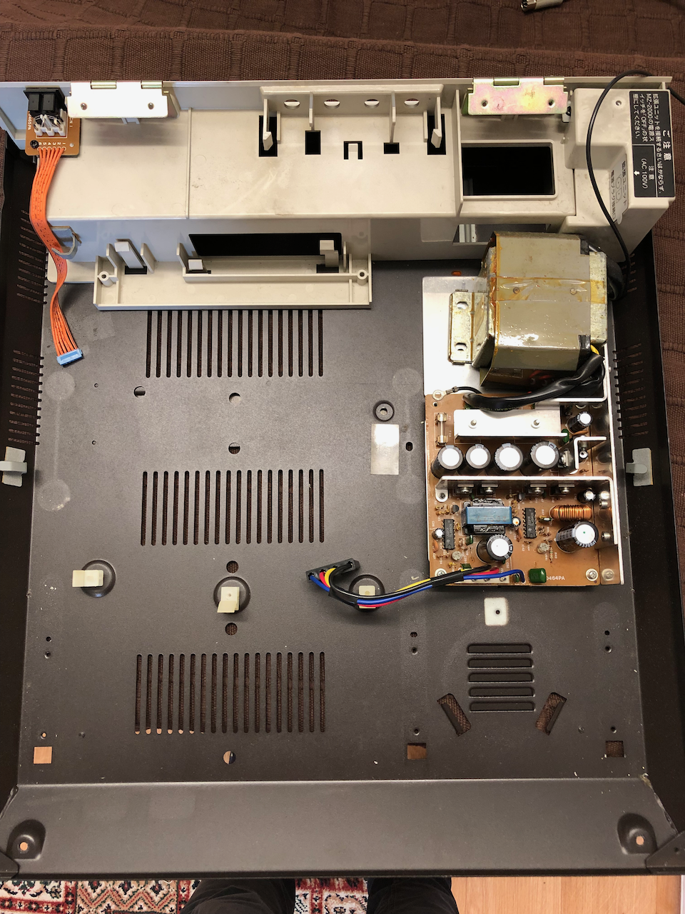
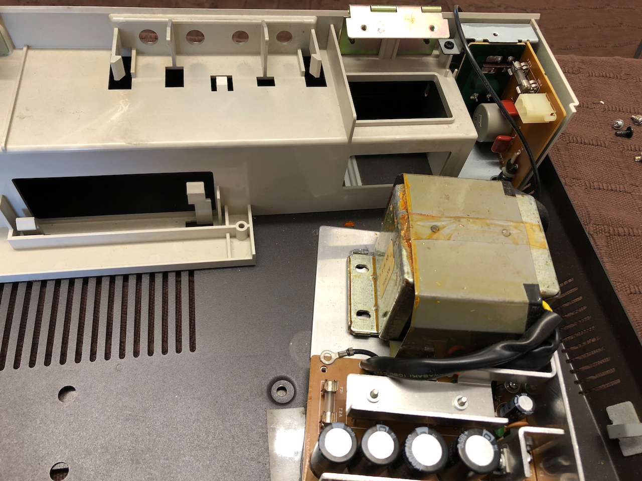
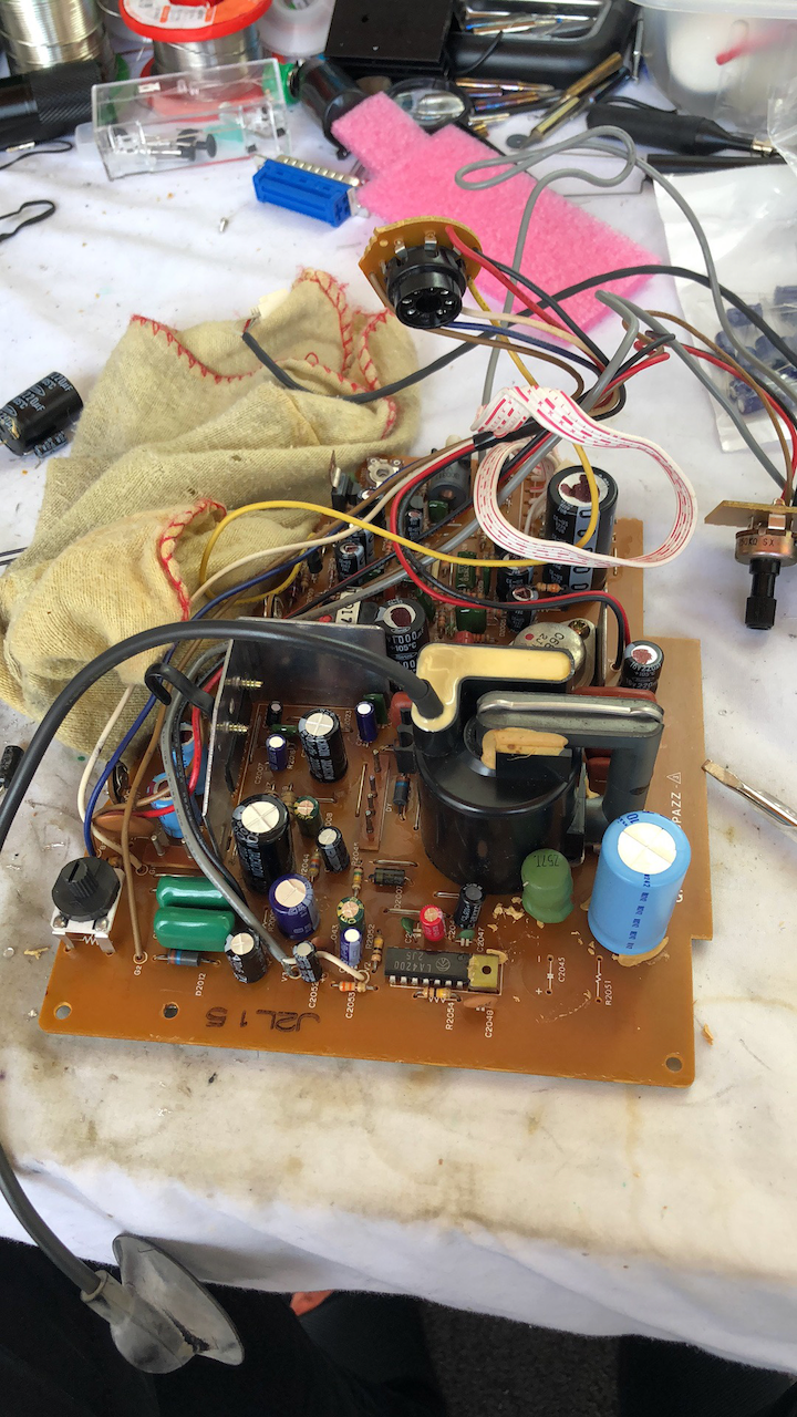
The power supply is installed as an assembled unit with a mains switched filtered input into a laminated transformer. The transformer and regulation circuit board are assembled onto a heatsink and the unit installed in the main body.
To clean and inspect the circuit board it needs to be disassembled and the heatsink removed.
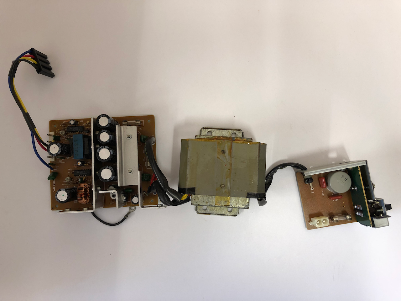
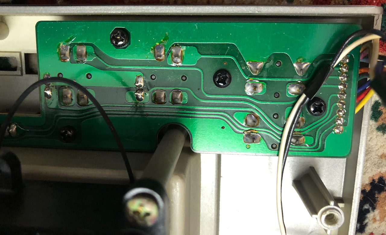
You can now inspect the underside of the PCB for capacitor leakage, cleaning and replacement of any/all damaged capacitors. As a minimum, the voltage spike/surge capacitors (often made by RIFA) need to be replaced along with the fuse.
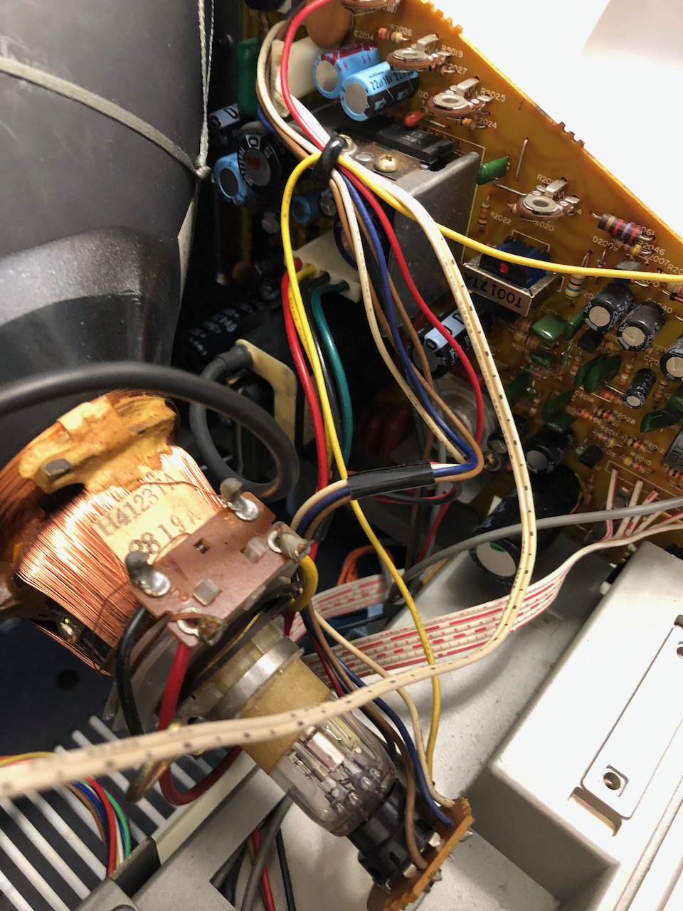
On the machine I plan to keep, I have upgraded the transformer to a toroid, removing the laminated transformer and mounting the toroid on a plastic plate using the original fixings. The chosen transformer is a 120VA 2x22VAC@2Amp + 15-0-15VAC@1Amp output and 2x115VAC primary input coils. The PSU requires 2x22VAC for +12V/+5V generation and 1x15VAC for -5V generation. The 2x115VAC primary coils can run in parallel (115V AC) or series (240V AC) which maintains a modicum of originality. In this installation the primary coils are set to work in series and an advantage of this setup with a higher output voltage is the machine can now take a full range mains input from 100VAC to 240VAC.
All the capacitors were upgraded to 35V units to ensure full range compliance given the higher toroid output.
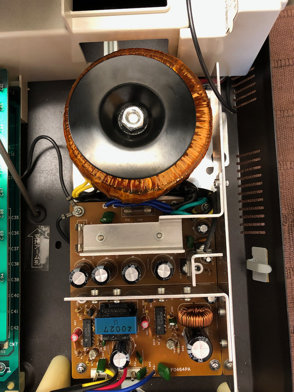
Prior to use, the voltages need to be checked and set, the -5V is fixed but +5V and +12V are set by the white topped variable resistor trim pots.
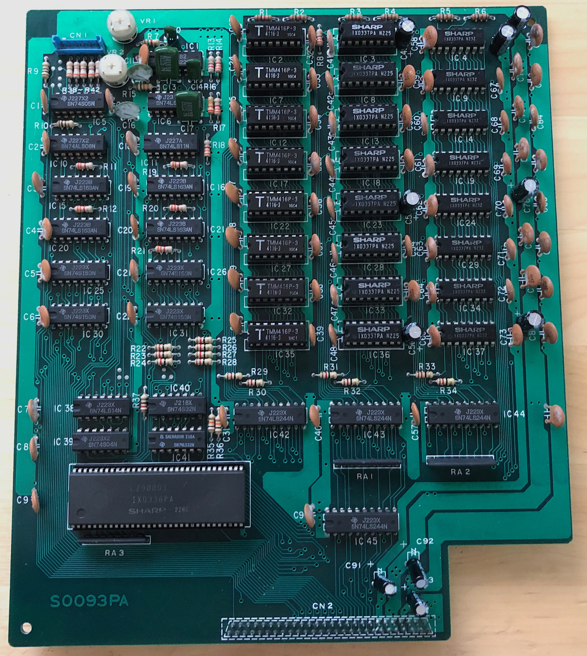
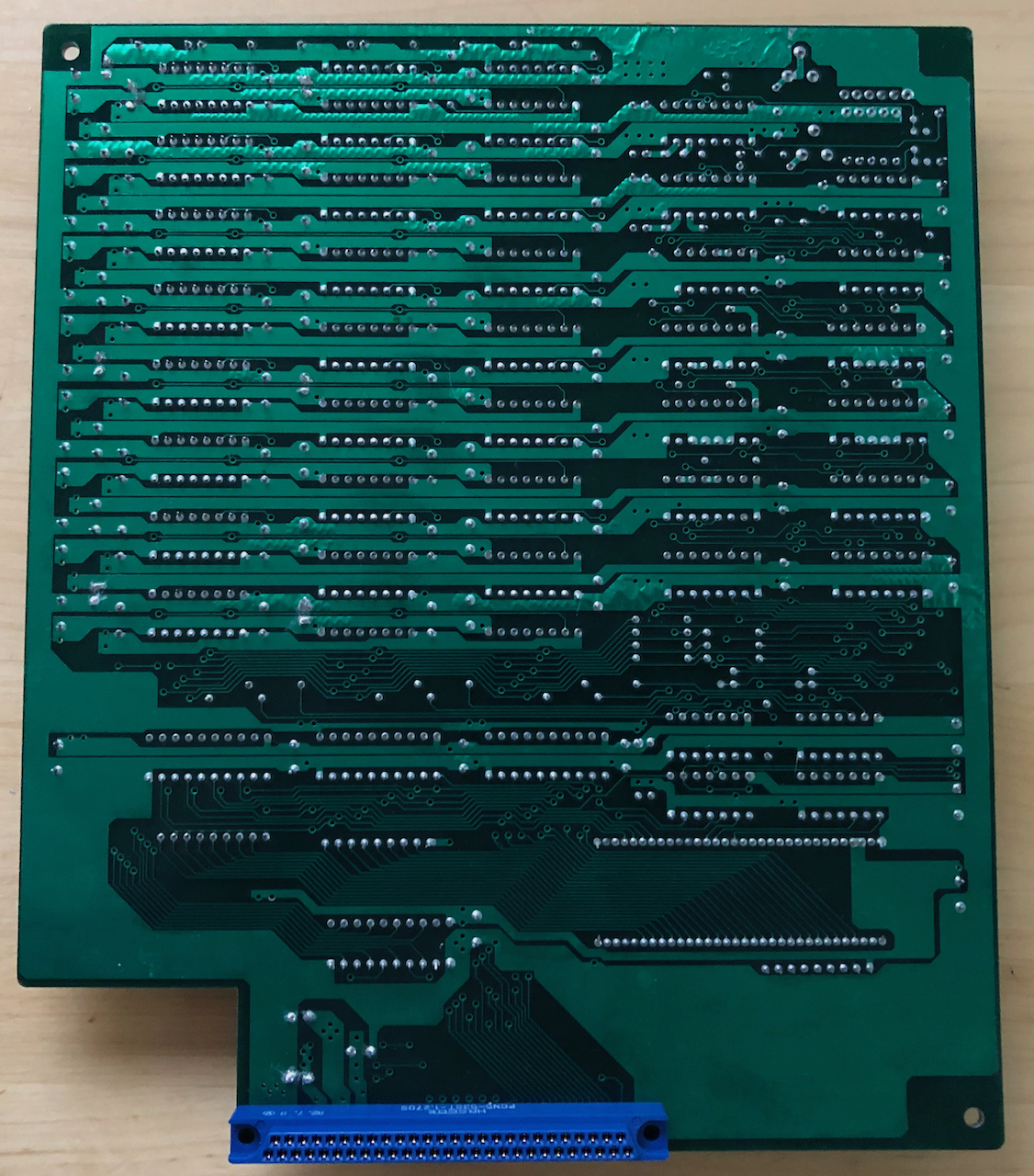
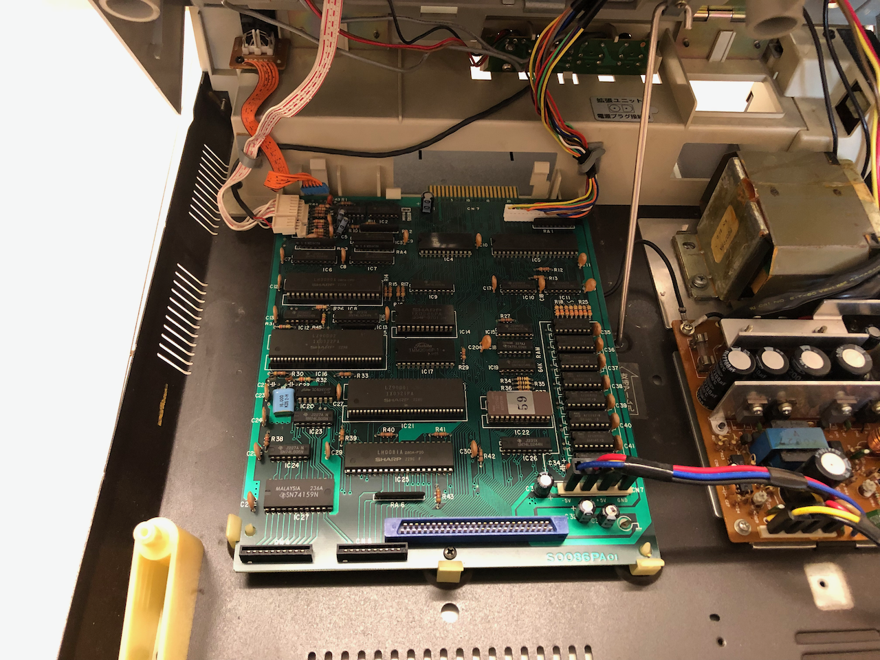
Mainboard
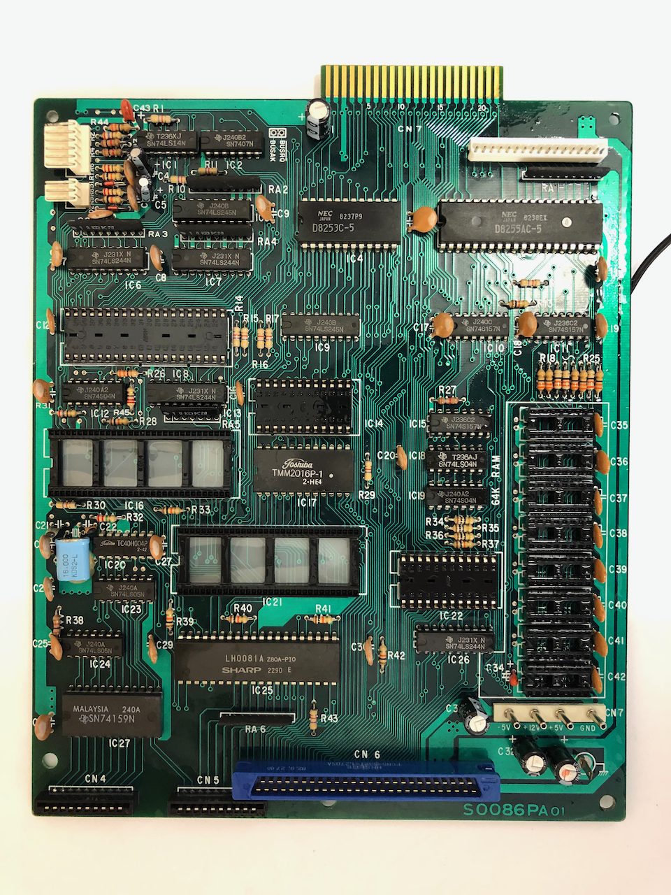
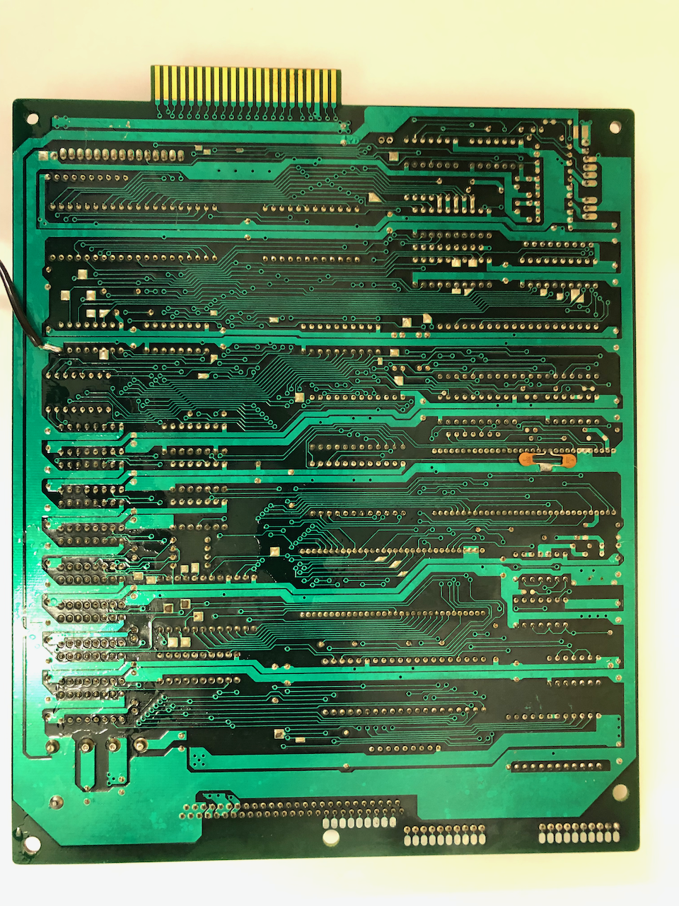
The mainboard needs to be cleaned with an air compressor (many are very dirty) and isopropyl alcohol. I removed all the socketed IC’s prior to cleaning and used contact cleaner in the sockets as I’ve come across a fair few machines which have badly oxidised. As the mainboard contains tantalum capacitors, early models having more than later models as they used 1 tantalum per DRAM IC, it is important to replace them, it is well published and I have personally experienced one on an X68000 going short circuit and damaging the board. The same for the electrolytics, when they age they lose their capacitance or go open circuit, not so dangerous as tantalums but spike suppresion or power demands may not be met leading to erroneous crashes and also RC timebase circuits will stop functioning or go out of calibration.
If the graphics board is installed, repeat the exercise and change all the tantalums and electrolytic capacitors, this board has a lot of DRAM IC’s and tantalum capacitors were sited near every third DRAM IC. I replaced them with high quality electrolytics.
Re-assembly
Re-assembly starts with the base casing plate, first attaching the upper casing (on which the monitor frame sits) which tends to be a bit tricky lining up the hinges, given the size and weight I found this best to be done on a carpet.
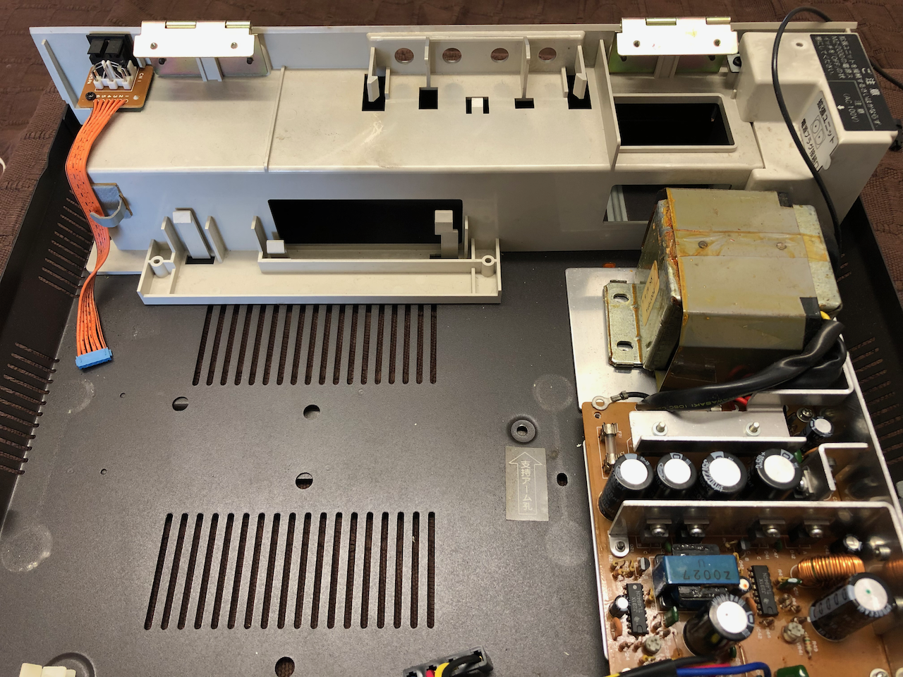
The power supply is then re-installed, placing the fuse/filter onto the frame first and fastening down followed by the main PSU assembly which requires two large bolts to hold the transformer to the base and two smaller screws on the front PCB.
The motherboard support standoffs are then re-inserted into the base and the motherboard fitted. The ground lead coming from the underside of the motherboard (a soldered wire with a screw clip on the other end is then screwed down to the PSU.
The keyboard support brackets are next installed.
The case base plate with the PSU, motherboard, keyboard brackets and upper case assembled.
The assembled fascia containing the monitor and cassette drive are mated to the casing top and fastened down with 3 screws.
The cables are connected to the mainboard/PSU.
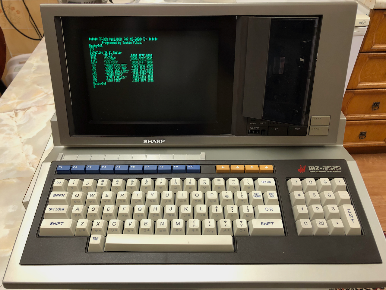
The finished machine, only the two screws under the keyboard need to be inserted to complete.
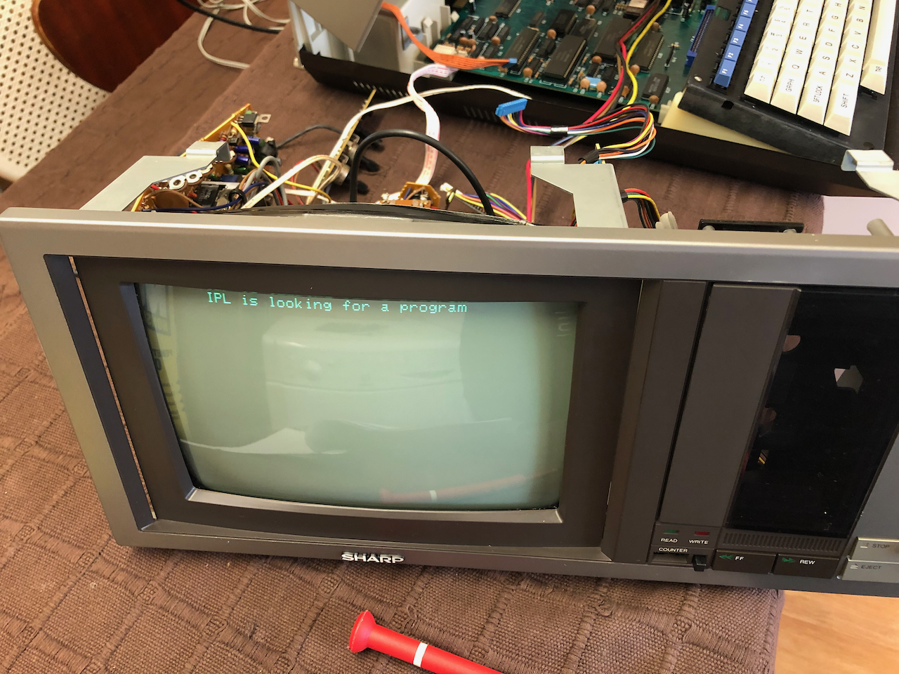
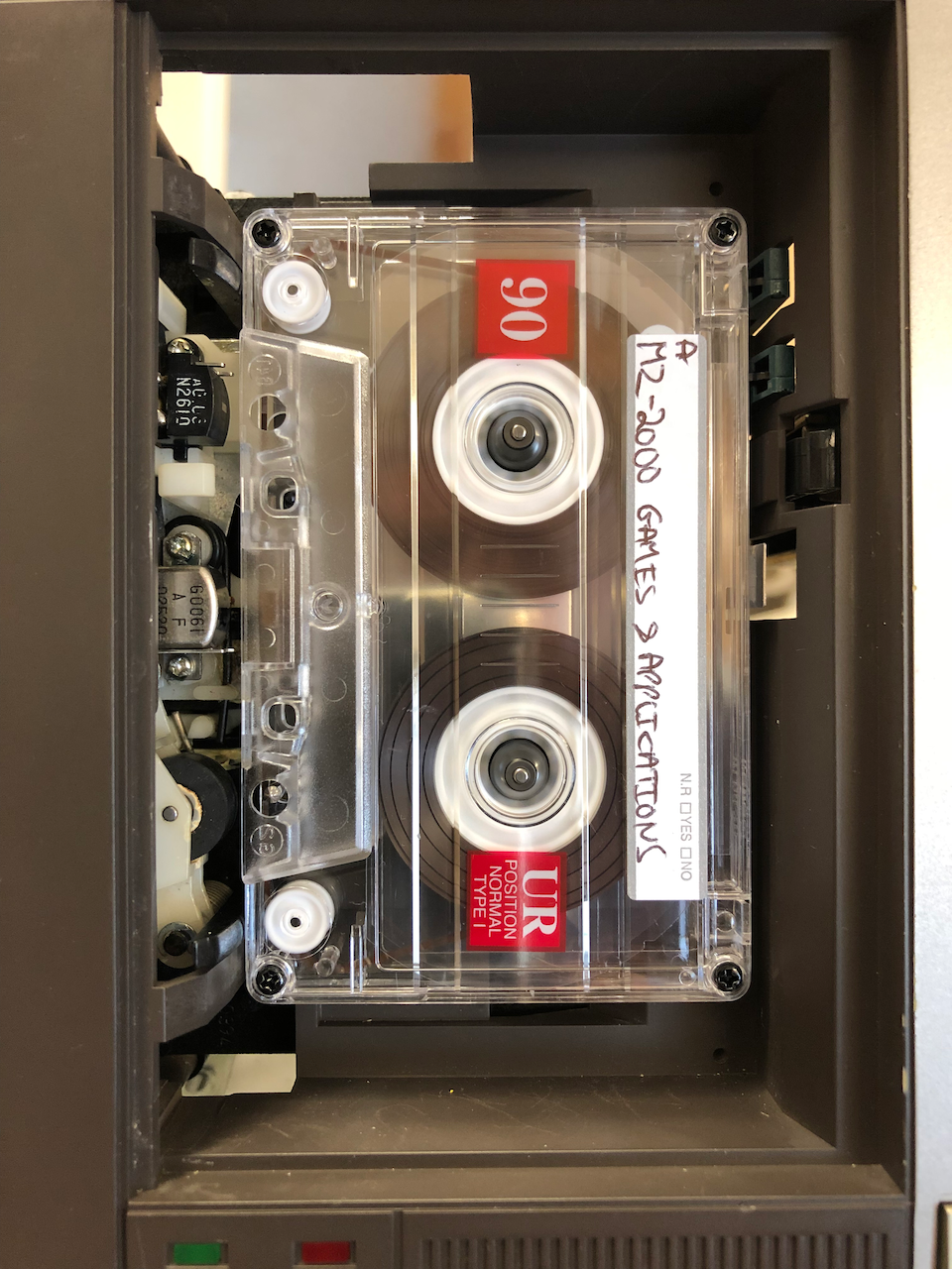
Finally a power on test and load of an application.
Credits
Licenses
The Gnu Public License v3
The source files are distributed in the hope that it will be useful, but WITHOUT ANY WARRANTY; without even the implied warranty of MERCHANTABILITY or FITNESS FOR A PARTICULAR PURPOSE. See the GNU General Public License for more details.
You should have received a copy of the GNU General Public License along with this program. If not, see http://www.gnu.org/licenses/.